Table of Contents
Advertisement
Quick Links
Advertisement
Table of Contents

Related Manuals for GE MG-101


Summary of Contents for GE MG-101
- Page 1 Measurement & Control Moisture MG-101 User’s Manual 910-115 Rev. E March 2012...
- Page 3 Measurement & Control MG-101 Field Moisture Calibration System User’s Manual 910-115 Rev. E March 2012 www.ge-mcs.com ©2012 General Electric Company. All rights reserved. Technical content subject to change without notice.
- Page 4 [no content intended for this page]...
-
Page 5: Safety Issues
Make sure that operators and maintenance personnel have all safety equipment applicable to the auxiliary equipment. Examples include safety glasses, protective headgear, safety shoes, etc. Unauthorized Operation Make sure that unauthorized personnel cannot gain access to the operation of the equipment. MG-101 User’s Manual... -
Page 6: Environmental Compliance
Environmental Compliance Waste Electrical and Electronic Equipment (WEEE) Directive GE Measurement & Control is an active participant in Europe’s Waste Electrical and Electronic Equipment (WEEE) take-back initiative, directive 2002/96/EC. The equipment that you bought has required the extraction and use of natural resources for its production. It may contain hazardous substances that could impact health and the environment. -
Page 7: Table Of Contents
A.3 Vapor Pressure and Calibration Tables..............18 MG-101 User’s Manual... - Page 8 Contents [no content intended for this page] MG-101 User’s Manual...
-
Page 9: Chapter 1. General Information
• Four adjustable rotameters (flowmeters with valves) • Saturator bottle • Filter • Temperature gauge • Vent valve See the diagram and explanation in Figure 1 on page 2 for a description of how the MG-101 works. MG-101 User’s Manual... - Page 10 Vent Valve Outlet Dry Down Valve Dry Gas Temp Dry Gas First Dilution Second 5µ Filter Flowmeter Dilution Flowmeter Wet Gas Wet Gas Diluted Flowmeter Flowmeter Saturator Dry Gas Bottle Inlet Pressure Regulator Figure 1: Flow Schematic MG-101 User’s Manuall...
-
Page 11: Initial Considerations
The driest dew/frost point temperature the MG-101 can produce is the dew/frost point temperature of the dry nitrogen source plus 25°C (45°F). If dry nitrogen of this quality is not available, please contact GE Sensing for assistance. The wettest dew/frost point temperature that can be generated is determined by the ambient temperature, and it must be at least 10°C (18°F) below the ambient temperature. - Page 12 Chapter 1. General Information [no content intended for this page] MG-101 User’s Manual...
-
Page 13: Chapter 2. Setup And Operation
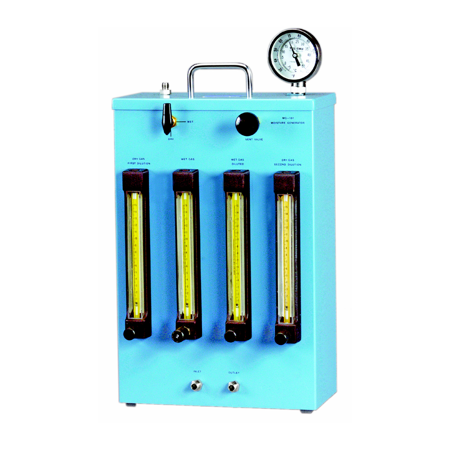
IMPORTANT: Be sure you read and understand “Initial Considerations” on page 3 before proceeding. To prepare the MG-101 for operation, complete the following steps: 1. Remove the back panel by removing the two small screws at the bottom (see Figure 2 below). - Page 14 5. Using the squeeze bottle, fill the saturator bottle until the water level reaches the fill mark on the bottle (see Figure 2 on page 5). 6. Close the petcock and reinstall the back panel. Wet/Dry Selection Valve Vent Valve Inlet Fitting Outlet Fitting Figure 3: MG-101 Front Panel MG-101 User’s Manuall...
- Page 15 Chapter 2. Setup and Operation 2.1 Preliminary Setup (cont.) 7. Connect the nitrogen supply to the MG-101 inlet fitting via the stainless steel pressure regulator using, 1/4” OD stainless steel tubing (see Figure 4 below). ® Note: Swagelok fittings are preferred throughout the installation.
-
Page 16: Operating Procedure
Chapter 2. Setup and Operation 2.2 Operating Procedure To operate the MG-101, refer to Figure 5 below and Figure 6 on page 9 to complete the following steps: 1. Fully close all four rotameter valves by turning them clockwise. 2. Set the... - Page 17 9. After the calibration system has reached equilibrium, set the valve on the WET/DRY rotameter to the position. Vent Valve Temperature Wet/Dry Gauge Selector Valve Wet Gas Wet Gas Diluted Dry Gas Dry Gas First Dilution Second Dilution Rotameters Figure 6: Rotameters and Valves MG-101 User’s Manual...
-
Page 18: Calibrating The Moisture Samples
. You will find that “drier” calibration points are in Data Table 3 while “wetter” values are in Data Table 2. At this point, the MG-101 operating procedure depends on which table contains your calibration point: • If your calibration point is in Data Table 3 , go to “Using Data Table 3”... -
Page 19: Using Data Table 3
After you have completed the calibration or other calibrated moisture operation at this dew/frost point temperature, either shut down the system (see “System Shutdown” on page 12), or repeat the steps in this section for the next calibration point. MG-101 User’s Manual... -
Page 20: Using Data Table 2
IMPORTANT: Be sure to read the steel ball or glass ball ( ), as indicated in the table. After equilibrium has been established, the MG-101 will be delivering a calibration gas with the selected dew/frost point temperature. After you have completed the calibration or other calibrated moisture operation at this dew/frost point temperature, either shut down the system (see “System Shutdown”... -
Page 21: Preparation For Shipping
Chapter 2. Setup and Operation 2.2.5 Preparation for Shipping To ship or to move the MG-101, refer to Figure 7 below and empty the saturator bottle as follows: 1. Remove the rear panel by removing the two small screws at the bottom. - Page 22 Chapter 2. Setup and Operation [no content intended for this page] MG-101 User’s Manual...
-
Page 23: Chapter 3. Specifications
Dimensions (W x H x D) 12” x 18” x 6” (304.8 mm x 457.2 mm x 152.4 mm) Inlet and Outlet Connections 1/4” Swagelok® tube fittings Note: See Figure 8 on page 16 for a dimensional drawing of the MG-101. MG-101 User’s Manual... - Page 24 Chapter 3. Specifications 3.3 Physical Specifications (cont.) 18.00” (457 mm) 12.00” (305 mm) Figure 8: MG-101 Moisture Generator Outline Dimensions MG-101 User’s Manual...
-
Page 25: Appendix A. Supplemental Information
Appendix A. Supplemental Information Appendix A. Supplemental Information A.1 Formulas The moisture content generated by the MG-101, as determined by the water vapor pressure, is calculated with the following equation: × --------------------------------------- ----------------------------------------------------------------------------- where:... -
Page 26: Typical Examples
The following examples show typical calculations based on the equations presented on the previous page. A.2.1 Example 1 is provided with the MG-101 to enable you to use the field calibration system to check sensor probe Data Table 2 calibration without calculating the value of p... - Page 27 2.408 2.367 2.765 2.718 2.672 2.626 2.581 3.013 2.962 2.912 2.862 2.813 3.280 3.225 3.171 3.117 3.065 3.568 3.509 3.451 3.393 3.336 3.880 3.816 3.753 3.691 3.630 4.217 4.147 4.079 4.012 3.946 4.579 4.504 4.431 4.359 4.287 MG-101 User’s Manual...
- Page 28 41.251 41.710 42.175 42.644 43.117 43.595 44.078 44.563 45.054 45.549 46.050 46.556 47.067 47.582 48.102 48.627 49.157 49.692 50.231 50.774 51.323 51.879 52.442 53.009 53.580 54.156 54.737 55.324 55.910 56.510 57.110 57.720 58.340 58.960 59.580 60.220 60.860 MG-101 User’s Manual...
- Page 29 308.90 311.40 314.10 316.60 319.20 322.00 324.60 327.30 330.00 332.80 335.60 338.20 341.00 343.80 346.60 349.40 352.20 355.10 358.00 361.00 363.80 366.80 369.70 372.60 375.60 378.80 381.80 384.90 388.00 391.20 394.40 397.40 400.60 403.80 407.00 410.20 413.60 MG-101 User’s Manual...
- Page 30 624.61 629.24 633.90 638.59 643.30 648.05 652.82 657.62 662.45 667.31 672.20 677.12 682.07 687.04 692.05 697.10 702.17 707.27 712.40 717.56 722.75 727.98 733.24 738.53 743.85 749.20 754.58 760.00 765.45 770.93 776.44 782.00 787.57 793.18 798.82 804.50 810.21 MG-101 User’s Manual...
- Page 31 AUTHORIZATION NUMBER (RAN), and shipping instructions for the return of the instrument to a service center will be provided. 2. If GE Sensing instructs you to send your instrument to a service center, it must be shipped prepaid to the authorized repair station indicated in the shipping instructions.
- Page 32 Warranty [no content intended for this page] MG-101 User’s Manual...
- Page 34 Customer Support Centers U.S.A. The Boston Center 1100 Technology Park Drive Billerica, MA 01821 U.S.A. Tel: 800 833 9438 (toll-free) 978 437 1000 E-mail: sensing@ge.com Ireland Sensing House Shannon Free Zone East Shannon, County Clare Ireland Tel: +353 (0)61 470291 E-mail: gesensingsnnservices@ge.com An ISO 9001:2008 Certified Company www.ge-mcs.com/en/about_us/quality.html...