
Related Manuals for Canon RC-IP100


Summary of Contents for Canon RC-IP100
- Page 1 Remote Camera Controller User Manual ENGLISH Make sure to read through this User Manual before using the product.
-
Page 3: Table Of Contents
Contents Content of this Manual Getting Started Symbols used Contents ................3 Caution : Describes precautions concerning the operation Supplied Accessories ............3 of this product. Memo : Describes reference information, such as Main Features ................ 4 functions and usage restrictions of this product. Precautions ................ -
Page 4: Main Features
Main Features Handling Precautions The following are the features when this unit is used in Do not rub against or press the surface of the combination with a remote camera. touch panel with a knife or a sharp object. Simple Operation with LCD Touch Panel Do not apply excessive force to this unit;... -
Page 5: Name Of Parts
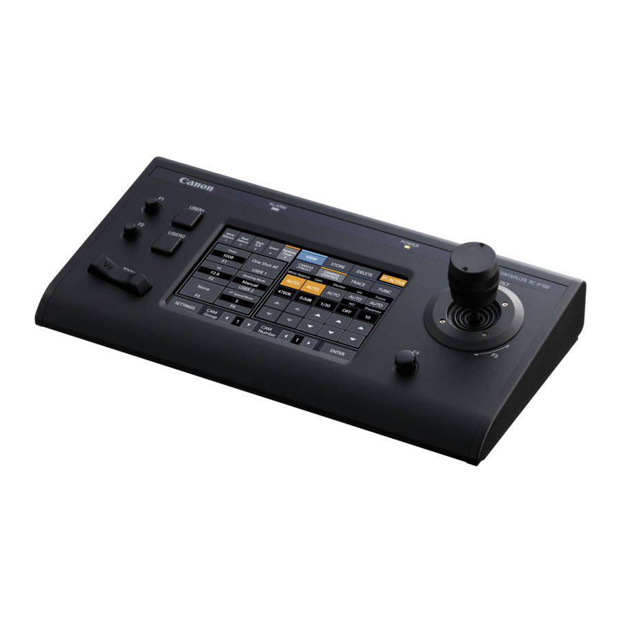
Name of Parts Rear Panel Front Panel B C D E A USER1 button For configuring the assigned features. B F1 knob A Power switch For adjusting the assigned features. For turning the power on or off. C F2 knob B Wire Clamp For adjusting the assigned features. - Page 6 Camera Operation Screen A Function Group Button I [CAM Group] Assigns a combination of the preconfigured functions as a The camera group can be altered using the left/right buttons. function group to a button or knob. J [CAM Number] (A P10 “Adjusting Using Function Group Buttons”) The camera number can be altered using the left/right 0 White Balance buttons.
-
Page 7: Preparations
Preparations N [CAMERA CONTROL] For controlling the currently selected camera. O [FUNC] 1 Set the power switch to “On”. For changing the settings of the currently selected camera. 0 The power is turned on and the POWER lamp lights up. P [TRACE] 0 The start screen is displayed on the operation panel. -
Page 8: Selecting And Operating A Camera
Selecting and Operating a Operating a Camera Camera Operating the PTZ (pan/ tilt/ zoom) 1 Select a camera to operate. Selecting a Camera (A P8 “Selecting a Camera”) Follow the steps below to specify a camera number and select 2 Tilt the control lever toward the direction you want a camera to operate. -
Page 9: Changing An Assigned Function
Changing an Assigned Function Selecting a Preset What is preset? This system allows multiple shooting positions and settings to be registered for one camera. Such a registered shooting position or setting is referred to as a “preset”. Up to 100 presets can be registered for a remote camera. -
Page 10: Adjusting The Camera Functions
Adjusting the Camera Adjusting Using FUNC Functions 1 Select a camera to operate. (A P8 “Selecting a Camera”) 2 Tap the [FUNC] tab. Adjusting Using Function Group Buttons 3 Adjust the Functions. If the function you want to select is not displayed, tap 1 Tap the Function Group button. -
Page 11: Setup Flow
Setup Flow Basic Operations of Menu Screen When setting up the system for the first time, or when new cameras are added, set up in the manner as follows. Be sure to perform an operation check after the setup. 1 Tap the [SETTINGS] button on the home screen. 1 IP address settings The settings menu appears. -
Page 12: Menu Screen Flow
Menu Screen Flow The menu screens consist of normal menu screen and settings menu screen. The flow of the each screen is as shown in the figures below. Normal Menu Screen VIEW Screen This screen is used for selecting a camera, selecting a camera preset, operating a camera and performing tracing. VIEW Screen CAMERA/PRESET... - Page 13 DELETE Screen This screen is used for deleting a camera preset or tracing. DELETE CAMERA/PRESET Screen Screen Home Screen TRACE Screen BUTTON CUSTOMIZATION Screen For assigning functions to the buttons and knobs of this unit. BUTTON CUSTOMIZATION Screen (*) Home Screen Home Screen * You can adjust the function that is highlighted without tapping...
- Page 14 Settings Menu Screen SETTINGS Screen For configuring the settings of this unit. Tap the [Back] button at the top right corner of the screen to return to the previous screen. Tap the [HOME] button at the bottom left corner of the screen to return to the home screen. (A P11 “Settings Menu”) Home Screen Video Screen...
-
Page 15: System Setup
System Setup 6 Tap the number button corresponding to the number of the camera to be configured. 0 Multiple cameras within the same group can be selected. Switching the Camera Video Output On/Off 0 Numbers that do not correspond to any of the existing cameras are indicated in white. -
Page 16: Network Settings
Network Settings [Serial Activate 1] and [Serial Activate 100] Serial Cameras 0 Serial cameras can be registered to <1-1> or <10-10>. Camera Network Settings (<Camera Group No.-Camera No.>) 0 Tap [Serial Activate 1] to register to <1-1> and tap [Serial Activate 100] to register to <10-10>. -
Page 17: Tally Setup
Configure the pin 4 and pin 5 functions of the tally terminal using the SETTING switch on the rear panel. (Maximum voltage 24 V) Other than pin 4 and pin 5, the remaining pin functions cannot RC-IP100 be changed. TALLY OUT (Maximum current... -
Page 18: Troubleshooting
This product includes third-party software modules. For the licensing terms of the respective modules, please refer to [HOME]>[SETTINGS]>[Open Source License]. Connection Diagram Serial camera IP camera IP camera LAN cable RS-422 cable RC-IP100 * Up to 100 cameras can be connected concurrently. Troubleshooting... -
Page 19: Specifications
Please refer to “About Cameras Compatible to the Remote Surrounding 0 °C to 40 °C (32 °F to 104 °F) (operation) Camera Controller RC-IP100” on the website. Please note that temperature some features might not be usable depending on the camera in... - Page 20 BIE-7290-000 B5A-3801-00 © CANON INC. 2021...