Advertisement
Quick Links
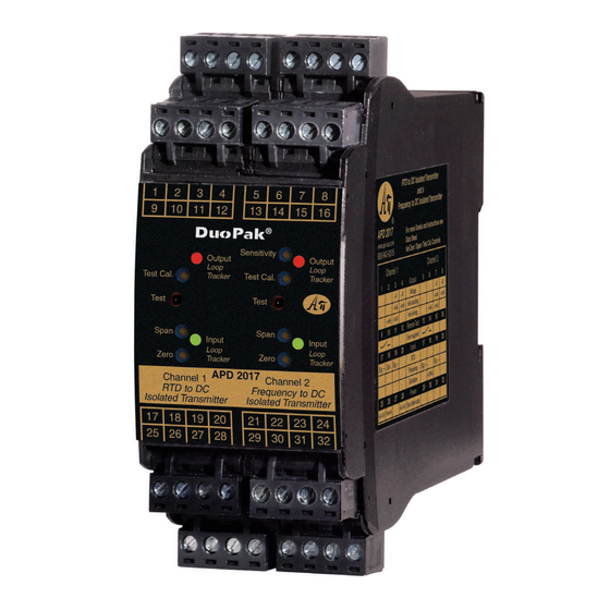
Two Channel Signal Converter/Isolator/Transmitter
®
Channel 1: RTD or Thermistor Temperature to DC
O Two Independent Channels with Full Isolation
O Zero and Span for Each Output
O Input and Output LoopTracker
LEDs
®
O Output Test/Manual Override for Each Channel
O Built-In I/O Power Supplies
Applications
Q Monitor Temperature and Speed
Q Convert/Isolate Dual Output Transmitters
Channel 1 RTD or Thermistor Input Range
Factory configured, please provide complete sensor specifica-
tions and temperature range. 100°F (55°C) minimum span.
RTD input:
Resistance at 0°C
Curve (385, 3916, 392 etc.)
Temperature range in °F or °C
RTD resistance: Typically 10 Ω to 2000 Ω, 2 or 3 wire
Excitation current: Typically 10 Ω: 10 mA, 100 Ω: 2 mA,
1000 Ω: 0.5 mA, 2000 Ω: 0.2 mA
Leadwire comp.: < ±0.05% of span per 1 Ω change in
leadwire resistance, 3 wire sensor
Thermistor input: Type (NTC or PTC)
Temperature curve data
Temperature range in °F or °C
Thermistor resist.: Typically 2 kΩ to 20 kΩ
Channel 2 Frequency Input Range
Factory configured, please specify input range
Frequency:
0-25 Hz to 0-20 kHz
Any waveform with 5 microsecond min. pulse, 100 mV min.
amplitude change, 100 mV to 150 V
RMS
Channel 2 Sensor Power Supply
15 VDC ±10%, regulated, 25 mADC, <10 mV
Channel 2 Characteristics
Impedance at max. sensitivity:
10 kΩ nom.
Impedance at min. sensitivity:
100 kΩ nom.
Sensitivity/hysteresis adjustment: Multi-turn potentiometer
Sensitivity/hysteresis range:
±25 mV to ±2.5 V typical
Normal mode protection:
200% of input rating
Common mode protection:
600 V input to ground
LoopTracker
Variable brightness LEDs indicate I/O levels for each channel
Channel 1 and Channel 2 Output Ranges
Factory configured, please specify for each output channel
Voltage:
0-1 VDC to 0-10 VDC, 10 mA max
up to 20 VDC with M19, M29, M39
Bipolar voltage:
±1 VDC to ±10 VDC
Current:
0-1 mADC to 0-25 mADC, 4-20 mADC
20 V compliance, 1000 Ω at 20 mA
Output Calibration
Multi-turn zero and span potentiometers for each output channel
±15% of span adjustment range typical
Characteristics
Accuracy: ±0.1% of span (incl. adj. resolution and linearity)
Output ripple and noise:
Less than 10 mV
Isolation:
Full 5-way, 1200 V
Response Time
70 milliseconds typical
Ambient Temperature Range and Stability
–10°C to +60°C operating ambient, <±0.04% span/°C stability
Output Loop Power Supplies
20 VDC nominal, regulated, 25 mADC for each output channel
May be selectively wired for sinking or sourcing mA output
Output Test
Front buttons set each output to test level when pressed
Each test level potentiometer adjustable 0-100% of span
Housing and Connectors
IP 40, requires installation in panel or enclosure
Mounts to standard 35 mm DIN rail
Eight 4-terminal removable connectors, 14 AWG max wire size
Power
85-265 VAC, 50/60 Hz or 60-300 VDC, 6 W maximum
D versions: 9-30 VDC or 10-32 VAC 50/60 Hz, 6 W maximum
BSOLUTE
Quick Link
api-usa.com/2000
Free Factory
I/O Setup!
H H H H H H
H H H H H
H H H H H H
H H H H H
H H H H H H
H H H H H
H H H H H H
H H H H H
H H H H H H
Made in USA
amplitude
max. ripple
RMS
Dimensions
1.78" W x 4.62" H x 4.81" D
45 mm W x 117 mm H x 122 mm D
Height includes connectors
Description
The APD 2017 DuoPak accepts one RTD or thermistor input
and one frequency input and provides two optically isolated DC
voltage or current outputs that are linearly related to the inputs.
The input ranges and the output ranges for each channel are
independent and can be specified as required. This provides an
economical two channel solution in one device.
Typical applications include signal conversion, isolation, and
redundancy (i.e. to prevent failure of the entire loop if one
device fails), or a combination of these.
Each input signal is filtered, amplified, and then passed
through an opto-coupler to the output stages. Full 5-way
isolation (input 1, input 2, output 1, output 2, power) make
this module useful for ground loop elimination, common mode
signal rejection, and noise pickup reduction.
Output Sink/Source Versatility
RMS
Standard on the APD 2017 are 20 VDC loop excitation sup-
minimum
RMS
plies for each output channel. These power supplies can be
selectively wired for sinking or sourcing allowing use with any
combination of powered or unpowered milliamp I/O devices.
How to Order
Models are factory ranged. See I/O ranges above left.
Ranges and options for each channel must be specified on order
Channel 1 input range
Channel 2 input range
Channel 1 output range
Channel 2 output range
Model
APD 2017
APD 2017 D
ROCESS NSTRUMENTS, Inc.
Sink or Source
mA Output for
Each Channel
Output LoopTracker
LED for Each
Channel
Adjustable Output
Test Function for
Each Channel
Zero and Span for
Each Channel
Input LoopTracker
LED for Each
Channel
Custom I/O Ranges
Sensor Power
Available for
Frequency Input
Universal
Power
Description
Power
85-265 VAC, 50/60 Hz or
DuoPak 2 channel
60-300 VDC
RTD-DC, Freq.-DC
converter/isolator/
9-30 VDC or 10-32 VAC
transmitter
1220 American Way Libertyville, IL 60048
800-942-0315
Phone:
Channel 2: Frequency to DC
LoopTracker
API exclusive features include four LoopTracker LEDs (green
for each input, red for each output) that vary in intensity with
changes in the process input and output signals.
These provide a quick visual picture of your process loop at all
times and can greatly aid in saving time during initial startup
and troubleshooting.
Output Test
An API exclusive feature includes output test buttons for each
channel to provide a fixed output (independent of the input)
when held depressed.
Terminals are also provided to operate the test functions
remotely for each channel. This also allows use as a remote
manual override to provide a temporary fixed output if desired.
The test output level for each channel is potentiometer adjust-
able from 0 to 100% of the output span. The output test greatly
aids in saving time during initial startup and/or troubleshooting.
Options and Accessories
Options—add to end of model number
R1
Channel 1 I/O reversal (i.e. 20-4 mA out)
R2
Channel 2 I/O reversal (i.e. 20-4 mA out)
R3
Channel 1 and channel 2 I/O reversal
M19 Channel 1 high voltage output >10 V up to 20 V
M29 Channel 2 high voltage output >10 V up to 20 V
M39 Channel 1 and channel 2 high voltage output
U
Conformal coating for moisture resistance
Accessory—order as separate line item
API BP4 Spare removable 4 terminal plug, black
api-usa.com
Fax: 800-949-7502
APD 2017
Removable Plugs
© 06-14
Advertisement

Related Manuals for Absolute Process Instruments DuoPak APD 2017


Summary of Contents for Absolute Process Instruments DuoPak APD 2017
- Page 1 Two Channel Signal Converter/Isolator/Transmitter APD 2017 ® Channel 1: RTD or Thermistor Temperature to DC Channel 2: Frequency to DC O Two Independent Channels with Full Isolation Sink or Source O Zero and Span for Each Output Removable Plugs mA Output for O Input and Output LoopTracker LEDs ®...
- Page 2 Instructions APD 2017 Electrical Connections Mounting Voltage Voltage WARNING! All wiring must be performed by a qualified electrician or The housing clips to a standard 35 mm DIN rail. The housing is IP40 Device 1 Device 2 instrumentation engineer. Consult factory for assistance. rated and should be mounted inside a panel or enclosure.