Table of Contents
Advertisement
Quick Links
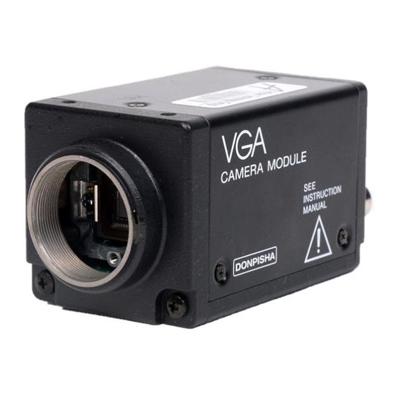
Black-and-White Video
Camera Module
取扱説明書
2
ペ−ジ
Operating Instructions
Before operating the unit, please read this manual thoroughly and retain it
for future reference.
お買い上げいただきありがとうございます。
電気製品は、安全のための注意事項を守らないと、
警告
火災や人身事故になることがあります。
この取扱説明書には、事故を防ぐための重要な注意事項と製品の取り扱いかたを
示してあります。この取扱説明書をよくお読みのうえ、製品を安全にお使いくだ
さい。お読みになったあとは、いつでも見られるところに必ず保管してください。
XC-7500
1995 by Sony Corporation
Page 48
3-800-478-04(1)
Advertisement
Chapters
Table of Contents

Summary of Contents for Sony XC-7500
- Page 1 3-800-478-04(1) Black-and-White Video Camera Module 取扱説明書 ペ−ジ Operating Instructions Page 48 Before operating the unit, please read this manual thoroughly and retain it for future reference. お買い上げいただきありがとうございます。 電気製品は、安全のための注意事項を守らないと、 警告 火災や人身事故になることがあります。 この取扱説明書には、事故を防ぐための重要な注意事項と製品の取り扱いかたを 示してあります。この取扱説明書をよくお読みのうえ、製品を安全にお使いくだ さい。お読みになったあとは、いつでも見られるところに必ず保管してください。 XC-7500 1995 by Sony Corporation...
- Page 2 日本語 警告 安全のために ソニー製品は安全に充分配慮して設計されています。 故障したら使わない しかし、 電気製品は、 まちがった使いかたをすると、 火 すぐに、お買い上げ店にご連絡ください。 災などにより死亡や大けがなど人身事故につながるこ とがあり、危険です。 万一、異常が起きたら 事故を防ぐために次のことを必ずお守りください。 1 本機が接続されて ・煙が出たら 安全のための注意事項を守る いる電源供給機器 ・異常な音、に 4〜6 ページの注意事項をよくお読みください。製品全 の電源を切る。 おいがしたら 般の注意事項が記されています。 2 DC電源ケーブルを 7ページの 「本機の性能を保持するために」 もあわせて ・内部に水、異 抜く。 物が入ったら お読みください。 3 お買い上げ店に連 ・製品を落とし 絡する。 定期点検をする たり、キャビ ネットを破損...
-
Page 3: Table Of Contents
目次 シャッターモードの選択とシャッタースピードの設定 ..警告 ..................E-DONPISHA モー ドのノ ーマルスピー ドのシャ ッ ター 注意 ..................スピー ド設定 ..............24 本機の性能を保持するために(使用上のご注意) ....E-DONPISHA の使いかた ..........特長 .................... E-DONPISHA 機能とは ..........26 システムの構成 ..............設定 ................... 27 構成品目一覧 ..............11 RESET モード / 映像出力 1V 目 ........29 各部の名称と働き... - Page 4 警告表示の意味 注意を促す記号 この取扱説明書および製品では、次のような表示 をしています。表示の内容をよく理解してから本 文をお読みください。 注意 火災 行為を禁止する記号 警告 この表示の注意事項を守らないと、火災などによ 分解禁止 禁止 り死亡や大けがなど人身事故につながることがあ ります。 行為を指示する記号 注意 強制 この表示の注意事項を守らないと、火災やその他 の事故によりけがをしたり周辺の物品に損害を与 えたりすることがあります。...
- Page 5 下記の注意を守らないと、 警告 火災 死亡 大けが などにより や につながることがあります。 火災 内部に水や異物を入れない 水や異物が入ると、火災の原因となります。 万一、水や異物が入ったときは、すぐに本機が接続されている電源供給機 禁止 器の電源を切り、 DC電源ケーブルや接続ケーブルを抜いて、 お買い上げ店 にご相談ください。 分解しない、改造しない 分解や改造をすると、火災やけがの原因となります。 内部スイッチを設定するときは、サービストレーニングを受けた技術者に 分解禁止 ご依頼ください。 点検および修理は、お買い上げ店にご依頼ください。...
- Page 6 下記の注意を守らないと、 注意 けが 損害 をしたり周辺の物品に を与えることがあります。 DC 電源ケーブルを傷つけない DC 電源ケーブルを傷つけると、火災や故障の原因となることがあります。 次の項目をお守りください。 禁止 ・ 設置時に、製品と壁やラック、棚などの間に、はさみ込まない。 ・ DC 電源ケーブルを加工したり、傷つけたりしない。 ・ 重いものをのせたり、引っ張ったりしない。 ・ 熱器具に近づけたり、加熱したりしない。 ・ DC 電源ケーブルを抜くときは、必ずプラグを持って抜く。 芯線の露出や断線などでDC電源ケーブルが傷んだら、 お買い上げ店に交換 をご依頼ください。そのまま使用すると、火災の原因となります。 設置・取り付けは確実に 設置については、必ずお買い上げ店にご相談ください。 壁面や天井などへの設置は、本機と取り付け金具を含む重量に充分耐えら 強制 れる強度があることをお確かめください。 充分な強度がないと、 落下して、 けがの原因となります。 また、1 年に 1 度は、取り付けがゆるんでいないことを点検してください。...
-
Page 7: 本機の性能を保持するために(使用上のご注意
本機の性能を保持するために (使用上のご注意) 指定された内部スイッチ以外には触れない 輸送 内部スイッチを設定するときは、この説明書で指定されたス 輸送するときは、付属のカートンとクッション、または同等 イッチ以外には触れないでください。 品で梱包し、強い衝撃を与えないようにしてください。 他の部分に触れると故障の原因となります。 お手入れ 使用・保管場所 レンズや光学フィルターの表面に付着したごみやほこり ● 次のような場所での使用および保管は避けてください。 は、ブロアーで払ってください。 −5℃ +45℃ 極端に暑い所や寒い所 (動作温度は 〜 ) 外装の汚れは、乾いたやわらかい布で軽く拭き取ってくだ ● ● 直射日光が長時間あたる場所や暖房器具の近く さい。汚れがひどいときは、中性洗剤溶液を少し含ませた ● 湿気、ほこりの多い所 布で汚れを拭き取った後、からぶきしてください。 ● 雨のあたる所 アルコール、ベンジン、シンナー、殺虫剤など揮発性のも ● ● 激しく振動する所 のをかけると、表面の仕上げをいためたり、表示が消えた ● 強い磁気を発するものの近く りすることがあります。 ●... - Page 8 特長 本機は、VGA (Video Graphic Array) フォーマット対応のイン VS (Video、Sync) 信号: ターライン型固体映像素子CCD (Charge Coupled Device) を採 VS信号 (映像信号または複合同期信号) により、外部同期 用した白黒ビデオカメラモジュールです。 で動作します。 (HD、VD信号による同期方式とVS信号 全画素独立読み出し方式により、約1/60秒ですべての画素信 による同期方式は、外部入力信号に応じて自動的に切り 号を独立して出力することができます。 換わります。) 多様なモード設定 内部同期信号出力 用途に応じた多様なモード設定が容易に行えます。 FLD信号 (フィールドインデックス信号) は、内部設定の変更 例えばゲインについては、後面スイッチの切り換えにより、 により6ピンコネクターより出力されます。 A (自動調整) 、F ( 固定) 、M (手動調整) の選択が、 γ (ガンマ) HD信号とVD信号は、内部スイッチを変更することにより、 については、内部スイッチの切り換えにより、ON (補正す 12ピンコネクターから出力させることができます。 る)...
- Page 9 豊富な電子シャッター機能 ノンインターレース機能 FA (ファクトリーオートメーション) などでの画像認識に欠か 後面のVIDEO OUT 1端子からフィールド1だけの映像を、 せない、電子シャッター機能を応用したCCDならではの数々 VIDEO OUT 2端子からフィールド2だけの映像を、1/60秒で の機能を搭載しました。 連続して出力し続けることができます。 電子シャッター ● FL (フリッカーレス) モードと豊富なシャッタースピード 筐体固定 (1/125〜1/10000秒) のなかから、撮影条件に合った速度が レンズマウント面に対して、高い精度で加工されたカメラモ 選べます。 ジュール固定用のネジ穴が設けてあります。このネジ穴を E-DONPISHA 1) (ドンピシャ) シャッター ● 使って本機を固定すれば、光軸のずれを最小限にとどめるこ E-DONPISHAとは、動く物体の撮影に適した外部トリガー とができます。 シャッターのことです。高速移動する被写体も、定位置か らブレの少ない画像として捉えることができます。 その他の特長 長寿命、高信頼性 ● リスタートリセット 画像ひずみが少なく精度の高い画像 ● 外部同期用のVDパルスを発生し、画像の取り込みと出力の 優れた耐振動衝撃性...
- Page 10 システムの構成 ビデオカメラモジュールXC-7500を中心としたシステムの構 成品目は、次のとおりです。 (本機以外はいずれも別売りで す。) 12ピンコネクター PC-XC12 カメラケーブル CCXC-12P02S (2 m) CCXC-12P05S (5 m) ビデオカメラモジュール メモリーアダプターCMA-87 6ピンコネクター PC-XC06 CCXC-12P10S (10 m) XC-7500 CCXC-12P25S (25 m) CCXC-6P05 (5 m) 推奨Cマウントレンズ VCL-50YM VCL-25YM VCL-16YM 三脚アタッチメント ジャンクションボックス VCL-12YM (標準) VCT-37 カメラアダプター JB-77 VCL-08YM VCT-75I (絶縁タイプ) DC-77RR...
-
Page 11: 構成品目一覧
構成品目一覧 三脚アタッチメント レンズ 三脚アタッチメントVCT-37 CマウントレンズVCL-50YM (f=50 mm、手動調整) 三脚アタッチメントVCT-75I (絶縁タイプ) CマウントレンズVCL-25YM (f=25 mm、手動調整) CマウントレンズVCL-16YM (f=16 mm、手動調整) カメラケーブル CマウントレンズVCL-12YM (f=12 mm、手動調整) 標準 CマウントレンズVCL-08YM (f=8 mm、手動調整) カメラケーブルCCXC-12P02S ( 2 m) カメラケーブルCCXC-12P05S ( 5 m) カメラケーブルCCXC-12P10S ( 10 m) カメラアダプター カメラケーブルCCXC-12P25S ( 25 m) カメラアダプターDC-77RR カメラケーブルCCXC-6P05S ( 5 m) ジャンクションボックス ジャンクションボックスJB-77 カメラケーブル接続用プラグ 12ピンコネクターPC-XC12 6ピンコネクターPC-XC06... -
Page 12: 前面・上面・底面
各部の名称と働き 前面・上面・底面 レンズマウント部 (Cマウント) 標準レンズVCL-12YMなど、Cマウント方式のレンズや光学 機器を取り付けます。 レンズマウント部 (Cマウント) 三脚取り付け用ネジ穴 三脚取り付け用ネジ穴 三脚を使うときに、このネジ穴を使って三脚アタッチメント VCT-37を取り付けます。 ◆ 詳しくは 「三脚の取り付け」 ( 17ページ) をご覧ください。 カメラ固定用基準穴 レンズマウント面に対して、高い精度で加工されたカメラモ ジュール固定用のネジ穴です。 上面前側と底面に同じネジ穴があります。 このネジ穴を使って本機を固定すると、光軸のずれを最小限 にとどめることができます。 ◆ 寸法など、詳しくはサービスマニュアル (別売り) をご覧く カメラ固定用基準穴 ださい。 (上面前側にも2穴あります。)... - Page 13 後面 手動ゲイン調整つまみ GAINスイッチ ( ) でMを選択した場合、このつまみでゲイン 手動ゲイン調整つまみ を調整できます。 (0〜+18dB) GAINスイッチ SHUTTERスイッチ GAIN (ゲインモード切り換え) スイッチ SIGNALスイッチ スイッチの切り換えにより、次のモードを選択できます。 DC IN ⁄ SYNC 2N 2I 1N SIGNAL A: 自動調整 ED N R.R SHUTTER F: 固定 A F M GAIN M:手動調整 LENS SHUTTER (シャッターモード切り換え) スイッチ スイッチの切り換えにより、次のモードを選択できます。...
- Page 14 各部の名称と働き SIGNAL (映像出力モード切り換え) スイッチ この端子のピン配置は下図のとおりです。 スイッチの切り換えにより、次のモードを選択できます。 ピン番号 信号 2N: VIDEO OUT 1端子とVIDEO OUT 2端子からODD、EVEN コントロール入力/ それぞれの同一フィールド信号を、1/60秒で連続して出 FLDパルス出力 力します。 外部トリガー入力 2I: VIDEO OUT 1端子とVIDEO OUT 2端子からODD、EVEN アース それぞれを、1/60秒のインターレース状態で出力しま WENパルス出力 す。 AI VIDEO出力 1N: VIDEO OUT 1端子からのみ1/30秒のノンインターレース DC+12V を出力します。 1番ピンについてのご注意 ご注意 出荷設定:コントロール入力 VIDEO OUT 2端子から映像信号は出力しません。 E-DONPISHAモード設定時、通常映像の出力が必要な場合は、 1番ピンをアースしてください (Low Voltageにしてください) 。 LENS (レンズ/外部コントロール) 端子 (6ピン) ◆詳しくは、お買い上げ店またはこの説明書の裏表紙に記載されている「お オートアイリスレンズからのレンズケーブルを接続すると、 問い合わせ」先までご相談ください。...
- Page 15 DC IN/SYNC (DC電源/同期信号入力) 端子 (12ピン) この端子のピン配置は下図のとおりです。 カメラケーブルCCXC-12P05Sを接続して、DC+12Vの電力 の供給を受け、本機からの映像信号を送出します。 また、同期信号発生器を接続して外部同期信号 (VSまたは HD/VD信号) を入力すれば、本機を外部同期で動作させるこ とができます。 外部同期モード ピン番号 カメラ同期信号出力 リスタートリセット HD/VD アース アース アース アース DC+12V DC+12V DC+12V DC+12V 映像出力1 ( アース) 映像出力1 ( アース) 映像出力1 ( アース) 映像出力1 ( アース) 映像出力1 ( 信号) 映像出力1 (...
-
Page 16: レンズの取り付け
設置 レンズの取り付け レンズマウントキャップを回して外す。 レンズ (別売り) を回して取り付ける。 レンズケーブル オートアイリスレンズを使用する場合は、レンズケーブ ルを本機後面のLENS端子に接続する。 (マニュアルアイリスレンズを使用する場合、手順3は不 要です。) 使用できるレンズ Cマウント方式のレンズで、レンズマウント面からの飛び出 し量が7 mm以下のものを使用してください。 レンズマウント面 7 mm以下... -
Page 17: 三脚の取り付け
三脚の取り付け 三脚アタッチメント (別売り) を本機底面にネジを使って 取り付ける。 三脚 (別売り) に取り付ける。 ご注意 三脚アタッチメント (別売り) を本機に取り付けるときは、 ● 長さ4 mm以内のネジ (三脚アタッチメントに付属) を使用し てください。 三脚 (別売り) の取り付け部のネジは次の規格のものを使用 ● してください。 ISO規格 n= 4.5 mm±0.2 mm ASA規格 n= 0.197インチ... -
Page 18: 接続例1
接続 接続例1 カメラモジュールを、AC電源用のアダプター (別売り) を介 ◆ カメラアダプターDC-77RR (別売り) の詳細については、 して電源に接続します。 DC-77RRの取扱説明書をご覧ください。 カメラケーブル 同期信号発生器 CCXC-12PO2S HD出力 VD出力 CCXC-12PO5S ビデオカメラモジュール EXT-SYNC V/RST CCXC-12P10S XC-7500 EXT-SYNC H DC IN/SYNC CCXC-12P25S 前面のカメラ接続用端子 VIDEO OUT2 カメラアダプター EXT-SYNC V/RST VIDEO OUT1 DC-77RR EXT-SYNC H VIDEO OUT AC電源へ 映像入力1 映像入力 映像入力2 VD出力 HD出力 他のカメラモジュール、 画像処理装置... -
Page 19: 接続例2
接続例2 カメラケーブル ジャンクションボックス ビデオカメラモジュール CCXC-12PO2S JB-77 XC-7500 DC IN/SYNC CAMERA CCXC-12PO5S CCXC-12P10S DC IN 12V (+) 12VDC VIDEO OUT LENS CCXC-12P25S 安定化電源 GND (−) CLOCK OUT HD IN VD IN VIDEO OUT1または2 AC電源へ 映像入力1 映像入力2 VD出力 映像入力 画像処理装置 モニター HD出力 同期信号発生器 トリガー出力 a) ジャンクションボックスJB-77のCLOCK OUT端子から映像信号2が出力 されます。... -
Page 20: 外部同期について
映像出力のモード 本機の映像信号の出力方法には、3つのモードがあります。 モードの選択は、本機後面のSIGNALスイッチで設定してく ださい。 外部同期について 内部同期はすべてのモードで使用できますが、外部同期 (EXT-HD/VD、EXT-SYNC) は選んでいるモードによっては 使用できないものがあります。 映像出力モード シャッターモード EXT-HD/VD :○ EXT-HD/VD :× EXT-HD/VD :○ ノーマル EXT-SYNC :○ EXT-SYNC :× EXT-SYNC :× EXT-HD/VD :× EXT-HD/VD :× RESETモード RESETモード EXT-SYNC :× EXT-SYNC :× E-DONPISHA EXT-HD/VD :○ EXT-HD/VD :○ NON-RESET NON-RESET モード... -
Page 21: 映像出力2Iモード
映像出力2Iモード VIDEO OUT 1端子とVIDEO OUT 2端子からODD、EVENそ 本機はEIA出力方式に対応しています。フィールド定義は以 れぞれを、1/60秒のインターレース状態で出力します。 下のようになります。 HD/VD の立ち下がりが一致 ODDフィールド HD/VD の立ち下がりが不一致 EVENフィールド 1/30秒 映像信号 1/60秒 複合同期信号 映像出力1 EVEN EVEN EVEN 映像出力2 EVEN EVEN EVEN 映像出力2Iモード時のタイミングチャート... -
Page 22: 映像出力2Nモード
映像出力のモード 映像出力2Nモード VIDEO OUT 1端子とVIDEO OUT 2端子からODD、EVENそ れぞれの同一フィールド信号を、1/60秒で連続して出力しま す。 1/30秒 映像信号 1/60秒 複合同期信号 映像出力1 EVEN EVEN EVEN EVEN EVEN EVEN 映像出力2 EVEN EVEN EVEN EVEN EVEN EVEN 映像出力2Nモード時のタイミングチャート... -
Page 23: 映像出力1Nモード
映像出力1Nモード VIDEO OUT 1端子からのみ1/30秒のノンインターレースを出 ご注意 力します。 VIDEO OUT 2端子から映像信号は出力しません。 1/30秒 映像信号 1/60秒 複合同期信号 映像出力1 映像信号なし 映像出力2 映像出力1Nモード時のタイミングチャート... -
Page 24: シャッターモードの選択とシャッタースピードの設定
シャッターモードの選択とシャッタースピードの設定 本 機 の シ ャ ッ タ ー モ ー ド の う ち 、 ノ ー マ ル モ ー ド と E - E-DONPISHAモードのノーマルスピードの DONPISHAモードでは、シャッタースピードを設定できます。 シャッタースピード設定 シャッターモードは本機後面のSHUTTERスイッチで選択しま す。シャッタースピードは内部スイッチで設定します。 SG-235基板の内部スイッチS6で、シャッタースピードを設定 SHUTTER シャッター します。 シャッタースピードの設定 スイッチ モード ◆内部スイッチS6の位置については42〜43ページをご覧くださ ノーマル MB-612基板のS2スイッチでスピード可変 ... - Page 25 X値、Y値、Z値の設定方法 前ページの設定例のシャッタースピードの精度は± %で す。これよりも高い精度を求める場合や、任意のシャッター X値 Y値 スピードにしたい場合は、次の計算式に基づいて設定してく ださい。 露光時間 [μs] シャッタースピード= ON ON ON ON 2.77 48.6 露光時間 =A× μs + μ A=(□× +□× +□× ) ON ON ON ON ON ON ON ON ON ON Z値 Y値 X値 ご注意 Aの値が13以下にならないように設定してください。 Z値 ON ON 注) 空欄はOFFです。...
-
Page 26: E-Donpishaの使いかた
E-DONPISHAの使いかた E-DONPISHA機能とは シャッタースピードは、ノーマルスピード、HIGH-SPEED、 外部から入力されるトリガーパルスを基準にして電荷を蓄積 LOW-SPEED、外部コントロールの4つから選べます。 し、連続した同期信号にのせて映像を出力する機能です。 高速で動く物体をセンサーで認識し、その映像を一定の場所 ノーマルスピード で正確に撮影できます。 HIGH-SPEED RESETモード トリガーパルスは本機後面のLENS端子 (6ピン) の2番ピンに (2I/1V) LOW-SPEED (29ページ) 入力してください。 外部コントロール ◆ 接続については 「接続」 ( ページ) をご覧ください。 ノーマルスピード RESET モード HIGH-SPEED E-DONPISHA 本機の 機能には次の つのモードがあります。 (2I/3V) LOW-SPEED (31ページ) RESETモード 外部コントロール E-DONPISHA トリガーパルスが入力されてから 同期信号がリセットさ モード... - Page 27 設定 内部スイッチの設定には、市販の調整棒をお使いください。 シャッタースピードを設定する。 ◆ 内部スイッチの配置など、詳しくは 「内部スイッチの働き」 ◆ 詳しくは 「E-DONPISHAモードのノーマルスピードの (38ページ) をご覧ください。 シャッタースピード設定」 ( 24ページ) をご覧ください。 SG-235基板の内部スイッチS7-3で、RESETモード (ON) ま HIGH-SPEED たはNON-RESETモード (OFF) を選ぶ。 SG-235基板の内部スイッチS7-5をON、S7-6をOFFにしてくだ さい。 手順1でRESETモードを選んだ場合は、SG-235基板の内部 スイッチS7-2で映像出力を3V (ON) または1V (OFF) に設定 LOW-SPEED する。 SG-235基板の内部スイッチS7-6をON、S7-5をOFFにしてくだ さい。...
- Page 28 E-DONPISHAの使いかた 設定(つづき) 外部コントロール SG-235基板の内部スイッチS7-5、S7-6をONにしてくださ い。 SG-235基板の内部スイッチS5を−側に設定してください。...
-
Page 29: Resetモード/映像出力1V目
RESETモード/映像出力1V目 出力モードは、2Iのみに対応しています。 HIGH-SPEED ノーマルスピード (SG-235基板の内部スイッチS7-2:OFF) シャッタースピード1/10000〜1/100000秒に対応しています。 トリガーパルスの入力と同時に 同期信号がリセットされ、 SG-235基板の内部スイッチS7-5をONにしてください。 後に映像が出力されるモードです。 1H=63.5μsec. ( 水平走査期間 ) トリガーパルス幅T2を任意に設定できます。 トリガーパルスが入力されてからできるだけ早いタイミング で映像を取り込みたい場合に適しています。 トリガーパルスの入力極性はSG-235基板の内部スイッチ で、 パルスの出力極性はSG-235基板の内部スイッチ で、切り換えられます。 任意設定(2μs〜90μs)トリガーパルス間隔:2V以上 トリガーパルス 31 H 1 ⁄ 60 s 1 ⁄ 60 s 任意設定(2μs〜10ms)トリガーパルス間隔:2V以上 トリガーパルス 映像出力1 31 H 1 ⁄ 60 s 1 ⁄... - Page 30 E-DONPISHAの使いかた RESETモード/映像出力1V目(つづき) 外部コントロール LOW-SPEED SG-235基板の内部スイッチS5を−側に設定してください。 SG-235基板の内部スイッチS7-6をONにしてください。 露光時間は入力トリガーによって制御されます。 SG-235基板の内部スイッチS7-5、S7-6をONに設定してくだ さい。 SG-235基板の内部スイッチS6にてT2 ( 100μs:1/10000s〜 1ms:1/1000s) を設定してください。 外部トリガーパルスのパルス幅T1を任意に設定することによ り、TX (露光時間) をコントロールできます。 任意設定(2μs以上)トリガーパルス間隔:2V以上 トリガーパルス 1 ⁄ 60 s 1 ⁄ 60 s 任意設定(2μs〜10ms) トリガーパルス 31 H トリガーパルス間隔:2V以上 ∞ ~ 映像出力1 1/60 s 露光時間 EVEN EVEN 複合同期信号...
-
Page 31: Resetモード/映像出力3V目
RESETモード/映像出力3V目 出力モードは、2Iのみに対応しています。 HIGH-SPEED ノーマルスピード (SG-235基板の内部スイッチS7-2:OFF) シャッタースピード1/10000〜1/100000秒に対応しています。 トリガーパルスの入力と同時に 同期信号がリセットされ、 SG-235基板の内部スイッチS7-5をONにしてください。 後に映像が出力されるモードです。 1H=64μsec. ( 水平走査期間 ) トリガーパルス幅T2を任意に設定できます。 トリガーパルスが入力されてからできるだけ早いタイミング で映像を取り込みたい場合に適しています。 トリガーパルスの入力極性はSG-235基板の内部スイッチ で、 パルスの出力極性はSG-235基板の内部スイッチ で、切り換えられます。 任意設定(2μs〜90μs)トリガーパルス間隔:4V以上 トリガーパルス 任意設定(2μs〜10m)トリガーパルス間隔:4V以上 31 H 1 ⁄ 60 s 1 ⁄ 60 s 1 ⁄ 60 s トリガーパルス 映像信号 31 H 1 ⁄... - Page 32 E-DONPISHAの使いかた RESETモード/映像出力3V目(つづき) LOW-SPEED 外部コントロール SG-235基板の内部スイッチS7-6をONにしてください。 SG-235基板の内部スイッチS5を−側に設定してください。 露光時間は入力トリガーによって制御されます。 SG-235基板の内部スイッチS7-5、S7-6をONに設定してくだ さい。 SG-235基板の内部スイッチS6にてT2 ( 100μs:1/10000s〜 1ms:1/1000s) を設定してください。 外部トリガーパルスのパルス幅T1を任意に設定することによ り、TX (露光時間) をコントロールできます。 任意設定(2μs以上)トリガーパルス間隔:4V以上 トリガーパルス 任意設定(2μs〜10ms) 映像出力1 トリガーパルス 31 H 1 ⁄ 60 s 1 ⁄ 60 s 1 ⁄ 60 s トリガーパルス間隔:4V以上 ∞ ~ 1/60 s 露光時間...
-
Page 33: Non-Resetモード(2I)の映像出力
NON-RESETモード(2I)の映像出力 HIGH-SPEED ノーマルスピード シャッタースピード1/10000〜1/100000秒に対応しています。 トリガーパルスが入力されてから、 目に映像が出力される SG-235基板の内部スイッチS7-5をONにしてください。 モードです。 トリガーパルス幅T2を任意に設定できます。 トリガー入力から映像出力までのタイミングは設定できませ んが、 同期信号の周期は一定です。画像処理システム側 で、一定周期の 同期信号が必要な場合に有効です。 S7-2 SG-235基板の内部スイッチ ( 映像出力 / ) の設定に は関係なく、トリガー入力から 目に映像出力されます。 トリガーパルスの入力極性はSG-235基板の内部スイッチ で、 パルスの出力極性はSG-235基板の内部スイッチ 任意設定(2μs〜90μs)トリガーパルス間隔:3V以上 トリガーパルス で、切り換えられます。 1 ⁄ 60 s 1 ⁄ 60 s 1 ⁄ 60 s 映像信号... - Page 34 E-DONPISHAの使いかた NON-RESETモード(2I)の映像出力(つづき) LOW-SPEED 外部コントロール SG-235基板の内部スイッチS7-6をONにしてください。 SG-235基板の内部スイッチS5を−側に設定してください。 SG-235基板の内部スイッチS7-5、S7-6をONに設定してくだ 露光時間は入力トリガーによって制御されます。 さい。 SG-235基板の内部スイッチS6にてT2 ( 100μs:1/10000s〜 1ms:1/1000s) を設定してください。 外部トリガーパルスのパルス幅T1を任意に設定することによ り、TX (露光時間) をコントロールできます。 任意設定(2μs以上)トリガーパルス間隔:3V以上 トリガーパルス 任意設定(2μs〜10ms) 1 ⁄ 60 s 1 ⁄ 60 s トリガーパルス トリガーパルス間隔:3V以上 ∞ ~ 映像信号 EVEN 1/60 s 露光時間 映像出力1 1 ⁄ 60 s 1 ⁄...
-
Page 35: Non-Resetモード(1N)の映像出力
NON-RESETモード(1N)の映像出力 HIGH-SPEED ノーマルスピード シャッタースピード1/10000〜1/100000秒に対応しています。 トリガーパルスが入力されてから、 目に映像が出力される SG-235基板の内部スイッチS7-5をONにしてください。 モードです。 トリガーパルス幅T2を任意に設定できます。 トリガー入力から映像出力までのタイミングは設定できませ んが、 同期信号の周期は下図のようになります。 S7-2 SG-235基板の内部スイッチ ( 映像出力 / ) の設定に は関係なく、トリガー入力から 目に映像出力されます。 トリガーパルスの入力極性はSG-235基板の内部スイッチ で、 パルスの出力極性はSG-235基板の内部スイッチ で、切り換えられます。 任意設定(2μs〜90μs)トリガーパルス間隔: トリガーパルス 4V+26H以上 *1フレーム 複合同期信号 映像信号 映像出力1 任意設定(2μs〜10ms)トリガーパルス間隔: トリガーパルス 複合同期信号のみ 4V+26H以上 *1フレーム 映像出力2 複合同期信号 映像信号 WENパルス... - Page 36 E-DONPISHAの使いかた NON-RESETモード(1N)の映像出力(つづき) 外部コントロール LOW-SPEED SG-235基板の内部スイッチS5を−側に設定してください。 SG-235基板の内部スイッチS7-6をONにしてください。 露光時間は入力トリガーによって制御されます。 SG-235基板の内部スイッチS7-5、S7-6をONに設定してくだ さい。 SG-235基板の内部スイッチS6にてT2 ( 100μs:1/10000s〜 1ms:1/1000s) を設定してください。 外部トリガーパルスのパルス幅T1を任意に設定することによ り、TX (露光時間) をコントロールできます。 任意設定(2μs以上)トリガーパルス間隔: トリガーパルス 4V+26H以上 *1フレーム 複合同期信号 映像信号 任意設定(2μs〜10ms) トリガーパルス間隔: トリガーパルス 映像出力1 4V+26H以上 ∞ ~ 複合同期信号のみ 1/60 s 露光時間 *1フレーム映像信号 映像出力2 複合同期信号 WENパルス 映像出力1 (−1V) 複合同期信号のみ...
- Page 37 リスタートリセット VDパルスを基準信号とした外部同期のかけかたです。 SG-235基板の内部スイッチS4でVDパルス数を設定する。 次の手順で設定してください。 ◆ VDパルスの設定は 「SG-235基板の内部スイッチの配 本機後面のSHUTTERスイッチをR.Rにする。 置と設定」 ( 43ページ) をご覧ください。 本機後面のSIGNALスイッチを2Iにする。 ご注意 2I以外のモードでは使用できません。 トリガーパルス HDパルス VDパルス 1回 長時間露光する場合 フィールド蓄積、画像を1フィールド VDパルス 2回 出力する場合 VDパルス 3回 フィールド蓄積、画像をフレーム出力する場合 VDパルス 4回 フィールド蓄積、画像を1フレーム出力する場合 A=525/2H リスタートリセットのタイミングチャート...
-
Page 38: 内部スイッチを設定するときのご注意
内部スイッチの働き 本機の内部スイッチの設定を変更することにより、VDパル ス数などの設定が可能になります。 内部スイッチを設定するときのご注意 注意 安全のため、次の項目を必ず守ってください。 本機と接続しているシステムの電源をすべて切って ● ください。 本機に接続されているケーブルをすべて外してくだ ● さい。 ステー 内部スイッチの設定は、市販の調整棒をお使いくだ ● さい。 基板を取り外さないでください。 ● (MB-612基板の内部スイッチを設定する場合を除く。) カバーの外しかた カバーを取り付けるには 外したときと逆の手順で取り付けてください。 ネジ6本を外し、カバーを外す。 ご注意 ステーを外す。 カバー上面のネジを最初に取り付けてください。... -
Page 39: 基板の配置
MB-612基板の内部スイッチの配置と設定 基板の配置 内部スイッチの設定はSG-235基板、PR-214基板、MB-612基 MB-612基板の内部スイッチを設定するには、他の基板を外 板の内部スイッチで行います。 す必要があります。以下の手順にしたがって他の基板を外し てください。 基板の配置は下図のとおりです。 PR-214基板を外す。 PS-383基板を外す。 SG-235基板 PS-383基板 ご注意 SG-235基板は絶対に外さないでください。 ● 後面 前面 基板は、必ず真上に引き抜いてください。 ● 基板を取り付けるには 外したときと逆の手順で取り付けてください。PR-214基板を 取り付けるときは、ガイドに沿って基板をはめ込んでくださ い。 前面 後面 ガイド PR-214基板 MB-612基板 ご注意 差し込むときは、コネクターとコネクターを確実に差し込ん 基板の配置 でください。差し込みが不充分な場合、正常に働かないこと があります。... - Page 40 内部スイッチの働き S1 ( 出荷設定:OFF) メモリーアダプターCMA-87を接続し、ハイレートスキャン モードなどを使用する場合にONにします。 ◆ 詳しくは、メモリーアダプターCMA-87の取扱説明書をご 覧ください。 S2 ( 出荷設定:0) シャッターモードがノーマルモードのときのシャッタース ピードを可変するスイッチです。設定するときは、本機後面 のSHUTTERスイッチをNの位置にしてください。 シャッター シャッター ポジション ポジション スピード (秒) スピード (秒) 1/2000 1/125 1/4000 1/250 1/10000 1/500 FL (フリッカーレス) 1/1000 FL (フリッカーレス) ◆ E-DONPISHAモードのノーマルスピードのシャッタースピー ド設定については、 「E-DONPISHAモードのノーマルスピー ドのシャッタースピード設定」 ( 24ページ) をご覧ください。 MB-612基板の内部スイッチの配置...
-
Page 41: 基板の内部スイッチの配置と設定
PR-214基板の内部スイッチの配置と設定 S1 ( 出荷設定:OFF) 映像出力1の γ 補正ON/OFFスイッチです。 S2 ( 出荷設定:M) ゲインを切り換えるスイッチです。 M:手動調整 A: 自動調整 RV19 RV7 RV2 RV18 S3 ( 出荷設定:OFF) RV21 映像出力2の γ 補正ON/OFFスイッチです。 RV17 RV20 RV10 RV9 RV8 RV23 RV14 RV13 RV22 RV15 RV11 RV12 PR-214基板の内部スイッチの配置... -
Page 42: 基板の内部スイッチの配置と設定
内部スイッチの働き SG-235基板の内部スイッチの配置と設定 – 1 · · · · · · · ·10 1 · · · · 6 TP11 OFF ON SG-235基板の内部スイッチの配置... - Page 43 S5 ( 出荷設定:+) S1 ( 出荷設定:ON) トリガーパルス入力極性の+ (正) /− (負) を切り換えるス 外部VD信号 75Ω終端のON/OFFスイッチです。 イッチです。 S2 ( 出荷設定:EXT) HD信号、VD信号を本機に入力 (EXT) するか、または本機か S6 ( 出荷設定:S6-9、S6-0はON、他はOFF) ら出力 (INT) するかを切り換えるスイッチです。 E-DONPISHAモードのノーマルスピードのシャッタースピー ドを設定するスイッチです。 S3 ( 出荷設定:ON) ◆ 設定については 「E-DONPISHAモードのノーマルスピード 外部HD信号 75Ω終端のON/OFFスイッチです。 のシャッタースピード設定」 ( 24ページ) をご覧ください。 S7 ( 出荷設定:すべてOFF) 外部同期時、RV1にてHの位相合わせが可能です。...
-
Page 44: Ccd特有の現象
CCD特有の現象 CCDカメラの場合、次のような現象が起きることがあります 折り返しひずみ が、故障ではありません。 縞模様、線などを写したとき、ぎざぎざのちらつきが見える ことがあります。 スミア 高輝度の被写体を写したときに、明るい帯状の縦線 (垂直ス 傷 ミア) がモニター画面に見える現象です。 (下図参照) CCDはフォトセンサー (素子) が縦横に並んでできており、 フォトセンサーのいずれかに欠陥があると、その部分だけ画 像が写らず、モニター画面に傷となって見えます (実用上支 縦に薄く尾を引いた 障がない程度) 。 ような画像になる。 (垂直スミア) モ ニ タ ー 微小白点 画面 高温時に暗い被写体を写している場合、画面全体に多数の白 高輝度の被写体 点が現れることがあります。 ( 電 灯 、 蛍 光 灯 、 太 陽、強い反射光など)... - Page 45 主な仕様 外部同期許容周波数偏差 撮像部 撮像素子 インターライン転送方式CCD ±1% (水平同期周波数にて) ジッター ±50 nsec以内 有効画素数 692 × 504 ( 水平/垂直) 走査方式 525本 撮像面積 1/2インチサイズ 2行同時走査 (2I/2Nモード) 光学黒期間 各水平走査線のうち33画素 1行順次走査 (1Nモード) CCD垂直駆動周波数 15.734 kHz±1% 映像出力 1.0Vp-p 同期負、75Ω不平衡 CCD水平駆動周波数 12.2727 MHz 水平解像度 500 TV本 信号方式 EIA方式 垂直有効ライン数 485本 セルサイズ 9.9 × 9.9 μm (水平/垂直) 400 lux、F4 ( γ 補正ON、0 dB) 感度...
- Page 46 主な仕様 シャッタースピード (ノーマルモード) FL (フリッカーレス) 、1/125、1/250、 1/500、1/1000、1/2000、1/4000、 1/10000秒 (内部スイッチで切り換え) 電源電圧 DC+12 V (+10.5〜15.0 V) 消費電力 2.5 W (±10%) 動作温度 −5℃〜+45℃ 保存温度 −25℃〜+60℃ 動作湿度 25〜80% (結露のない状態で) 保存湿度 20〜90% (結露のない状態で) 耐震動性 7 G (11 Hz〜200 Hz) 耐衝撃性 70 G 外形寸法 44×44×70 mm (幅/高さ/奥行き) (突起部含まず) 質量 約190 g 付属品 レンズマウントキャップ (1) 取扱説明書 (1) 仕様および外観は、改良のため予告なく変更することがあり...
- Page 48 Part 15 of the FCC Rules. These limits are designed provided below. Refer to these numbers whenever you call upon your Sony dealer regarding this product. to provide reasonable protection against harmful interference when the equipment is operated in a commercial environment.
- Page 49 Table of Contents WARNING Features ................46 The NON-RESET mode (2I) video out ..... 77 Precautions ..............48 The NON-RESET mode (1N) video out ....79 Typical CCD Phenomena ..........49 The Restart/Reset Mode ..........81 System Components ............50 Internal Switch Function ..........
-
Page 50: Features
Features The XC-7500 is a black-and-white video camera module VS (Video/Sync) signals: that uses a CCD (Charge Coupled Device) solid-state image The video camera module can be synchronized with an sensor compatible with the VGA (Video Graphic Array) external video or composite sync signal. (The unit format. - Page 51 Restart/Reset function Accurately picks up and outputs an object from the desired and fixed position by generating the VD pulses for external synchronization. You can set the number of VD pulses (1 to 4) and change the charging time for long exposure, depending on your particular operating conditions.
-
Page 52: Precautions
• Close to generators producing powerful electromagnetic quality. radiation, such as radio or TV transmitters In the event of any problems with the operation of the video camera module, contact your Sony service representative. -
Page 53: Typical Ccd Phenomena
Typical CCD Phenomena The following effects on the monitor screen are Vertical aliasing characteristic of CCD cameras. They do not indicate any When you shoot vertical stripes or lines, they may appear fault with the camera module. jagged. Smear Blemishes This occurs when shooting a very bright object such as A CCD image sensor consists of an array of individual electric lighting, the sun, or a strong reflection (shown... -
Page 54: System Components
System Components Pictured below are the components of the XC-7500 video All products other than the XC-7500 Video Camera camera module system. Module are optional (not supplied). PC-XC12 Connector (12-pin) Camera Cables CCXCC-12P02S (2 m [6.6 feet]) PC-XC06 Connector (6-pin) -
Page 55: Accessories
Accessories Lenses Tripod attachments VCL-50YM C-mount lens (f = 50 mm, manual focus) VCT-37 tripod attachment VCL-25YM C-mount lens (f = 25 mm, manual focus) VCT-75I tripod attachment (insulated type) VCL-16YM C-mount lens (f = 16 mm, manual focus) Camera cables VCL-12YM C-mount lens (f = 12 mm, manual focus) [standard lens] CCXCC-12P02S (2 m [6.6 feet]) -
Page 56: Location And Function Of Parts And Controls
Location and Function of Parts and Controls Front Panel/Top Panel/Bottom Panel 1 Lens mount (C-mount) Attach a VCL-12YM standard lens, or any C-mount lens or other optical equipment. 1 Lens mount (C-mount) 2 Tripod screw holes Use these screw holes to attach the tripod attachment 2 Tripod screw holes (VCT-37) to the camera module. -
Page 57: Rear Panel
Rear Panel 1 Manual gain control Controls the gain level (0 to +18 dB) in manual gain mode 1 Manual gain control (with the GAIN switch set to M). 2 GAIN switch 2 GAIN switch 3 SHUTTER switch Use this switch to select the following modes: 4 SIGNAL switch A: Automatic F: Fixed... - Page 58 VIDEO OUT 2 connectors. For details, contact the store of purchase or your 2I : The ODD/EVEN signals are output in the interlace authorized Sony dealer. mode for 1/60 sec. from the VIDEO OUT 1 and VIDEO OUT 2 connectors.
- Page 59 8 DC IN/SYNC (DC power input/sync signal I/O) The pin configuration of this connector is as follows: connector (12-pin) Connect a CCXC-12P05S camera cable to this connector, the +12 V DC power supply, and the video signal output from the camera module. When a sync signal generator outputting external sync signals is connected to this connector, the camera module is synchronized with the external sync signals.
-
Page 60: Installation
Installation Mounting a Lens To mount a lens on the camera module, follow steps 1 to 3. Turn the lens mount cap and remove it. Mount the lens (not supplied) by screwing it on. Lens cable When using an auto-iris lens, connect the lens cable to the LENS connector on the rear panel of the camera module. -
Page 61: Using A Tripod
Using a Tripod Fix the tripod attachment (not supplied) to the bottom panel of the camera module using the four screws supplied with the tripod attachment. Mount the camera module on the tripod (not supplied). Notes • To fix the tripod attachment (not supplied) to this unit, use four screws with a maximum length of 4 mm, or the screws supplied with the tripod attachment. -
Page 62: Connections
Connect the camera module to an AC power adaptor (not For details, refer to the operating instructions for the supplied) for the AC power source. DC-77RR Camera Adaptor. Sync signal generator Camera cable HD output VD output XC-7500 CCXC-12P02S Video EXT-SYNC V/RST CCXC-12P05S Camera CCXC-12P010S Camera connector... -
Page 63: Connection Example 2
Connection Example 2 XC-7500 Camera cable Video CCXC-12P02S Camera CCXC-12P05S DC IN/SYNC CAMERA Module CCXC-12P10S DC IN 12 V (+) 12 V DC JB-77 CCXC-12P25S VIDEO OUT LENS Power Junction transformer GND (–) CLOCK OUT HD IN VD IN AC power... -
Page 64: Video Output Modes
Video Output Modes There are three methods to output video signals with this Set the video output mode with the SIGNAL switch on the camera module. rear panel. External Synchronization You can use internal synchronization in any mode, but you cannot use external synchronization (EXT-HD/VD, EXT- SYNC) in certain modes. -
Page 65: The Video Signal 2I Mode
The Video Signal 2I Mode In this mode, the camera module outputs ODD and EVEN The camera module is corresponded to the EIA format. signals from the VIDEO OUT 1 and VIDEO OUT 2 The field definition is as follows: connectors in a 1/60 sec. -
Page 66: The Video Signal 2N Mode
Video Output Modes The Video Signal 2N Mode In this mode, the camera module continuously outputs identical ODD and EVEN field signals from the VIDEO OUT 1 and VIDEO OUT 2 connectors every 1/60 seconds. 1/30 sec. SIGNAL 1/60 sec. SYNC Video output 1 EVEN... -
Page 67: The Video Signal 1N Mode
The Video Signal 1N Mode Note In this mode, the camera module outputs only 1/30 sec. No video signals are output from the VIDEO OUT 2 non-interlace signals from the VIDEO OUT 1 connector. connector. 1/30 sec. SIGNAL 1/60 sec. SYNC Video output 1 NO SIGNAL... -
Page 68: Selecting Shutter Mode And Setting Shutter Speed
Selecting Shutter Mode and Setting Shutter Speed The shutter speed can be set for both normal operation and Shutter Speed Setting for Normal Speed in DONPISHA operation. Select the shutter mode with the the E-DONPISHA Mode SHUTTER switch on the rear panel, and set the shutter speed with the internal switches. - Page 69 The precision of the fixed speed in the settings example on Setting the X, Y, and Z parameters the previous page is ±10%. For higher precision or nonstandard shutter speed, obtain the shutter speed from the following equation. Exposure duration [µs] Shutter speed = —————————...
-
Page 70: Using The E-Donpisha Function
Using the E-DONPISHA Function What Is the E-DONPISHA Function? A charge starts building up the instant an external trigger You can set the shutter speed in the following four modes: signal is input, and then a 1-field image is output. The normal speed, high speed, low speed, or external control. -
Page 71: Setting The E-Donpisha Function
Setting the E-DONPISHA Function Use an adjusting rod to adjust the internal switches. Set the shutter speed. For details on internal switch locations, see “Internal For details, see “Shutter Speed Setting for Normal Switch Function” on page 82. Speed in the E-DONPISHA Mode” on page 68. Select the RESET mode (ON) or NON-RESET mode High speed (OFF) by setting the S7-3 switch on the SG-235 board. - Page 72 Using the E-DONPISHA Function Setting the E-DONPISHA Function External control Set the switch S7-5 and S7-6 on the SG-235 board to ON. Set switch S5 on the SG-235 board to minus (–).
-
Page 73: The Reset Mode (1V) Video Out
The RESET mode (1V) video out The output mode is compatible with 2I only. Normal-speed High-Speed (The S7-2 switch on the SG-235 board: OFF) The shutter speeds compatible with this function are When the trigger pulse is input, the V sync signal is reset, 1/10000 to 1/100000 sec. - Page 74 Using the E-DONPISHA Function The RESET mode (1V) video out (continued) Low-Speed External Control To set to low speed, set the S7-6 switch on the SG-235 Set the S5 switch on the SG-235 board to the minus (–) board to ON. The exposure duration is controlled by the position.
-
Page 75: The Reset Mode (3V) Video Out
The RESET mode (3V) video out The output mode is compatible with 2I only. Normal-speed High-Speed (The S7-2 switch on the SG-235 board: ON) The shutter speeds compatible with this function are 1/10000 to 1/100000 sec. To set to high speed, set the S7-5 The video signal is output at 3 V after the trigger pulse is switch on the SG-235 board to ON. - Page 76 Using the E-DONPISHA Function The RESET mode (3V) video out (continued) Low-Speed External Control To set to low speed, set the S7-6 switch on the SG-235 Set the S5 switch on the SG-235 board to the minus (–) board to ON. The exposure duration is controlled by the position.
-
Page 77: The Non-Reset Mode (2I) Video Out
The NON-RESET mode (2I) video out Normal-speed High-Speed This mode outputs the video signal at 2 V after the trigger The shutter speeds compatible with this function are 1/10000 to pulse is input. 1/100000 sec. To set to high speed, set the S7-5 switch on the SG- You cannot set the timing (from the trigger input to the video 235 board to ON. - Page 78 Using the E-DONPISHA Function The NON-RESET mode (2I) video out (continued) Low-Speed External Control To set to low speed, set the S7-6 switch on the SG-235 Set the S5 switch on the SG-235 board to the minus (–) position. board to ON. The exposure duration is controlled by the Set the S7-5 and S7-6 switches on the SG-235 board to ON.
-
Page 79: The Non-Reset Mode (1N) Video Out
The NON-RESET mode (1N) video out Normal-speed High-Speed This mode outputs the video signal at 2 V after the trigger The shutter speeds compatible with this function are 1/10000 to pulse is input. 1/100000 sec. To set to high speed, set the S7-5 switch on the SG- You cannot set the timing (from the trigger input to the video 235 board to ON. - Page 80 Using the E-DONPISHA Function The NON-RESET mode (1N) video out (continued) Low-Speed External Control To set to low speed, set the S7-6 switch on the SG-235 Set the S5 switch on the SG-235 board to the minus (–) position. board to ON. The exposure duration is controlled by the Set the S7-5 and S7-6 switches on the SG-235 board to ON.
-
Page 81: The Restart/Reset Mode
The Restart/Reset Mode You can set the synchronization externally with a VD pulse Set the VD pulse with the S4 switch on the SG-235 as a reference signal. Set the synchronization as follows: board. Set the SHUTTER switch at the rear of the unit to R.R. For details on how to set the VD pulse, see “Location and Setting of the Internal Switches on the SG-235 Board”... -
Page 82: Internal Switch Function
Internal Switch Function The internal switches enable you to change the camera settings (such as number of VD pulses, etc.). Precautions on Setting the Internal Switches For your safety, follow these precautions. • Turn off the power for the whole system connected to this camera. -
Page 83: Location Of Boards
Location of Boards Location and Setting of the Internal Switches on the MB-612 Board The internal switches are located on the SG-235, the PR- 214, and the MB-612 boards. You must remove the PR-214 and PS-383 boards before The following figure shows where the boards are located. setting the internal switches on the MB-612 board. - Page 84 Internal Switch Function S1 (Factory setting: OFF) Set to ON when you connect to the CMA-87 Memory Adaptor and use functions of the CMA-87, such as the hi- rate scan mode. For details, refer to the operating instructions for the CMA-87 Memory Adaptor.
-
Page 85: Location And Setting Of The Internal Switches On The Pr-214 Board
Location and Setting of the Internal Switches on the PR-214 Board S1 (Factory setting: OFF) Toggles the γ (gamma) compensation of video output 1 ON and OFF. S2 (Factory setting: M) Use this switch to select the following gain control setting: M: Manual A: Automatic RV19... -
Page 86: Location And Setting Of The Internal Switches On The Sg-235 Board
Internal Switch Function Location and Setting of the Internal Switches on the SG-235 Board – 1 · · · · · · · ·10 1 · · · · 6 TP11 OFF ON Location and Setting of the Internal Switches on the SG-235 Board... - Page 87 S1 (Factory setting: ON) S5 (Factory setting: +) Toggles the external VD signal 75-ohm termination ON Changes the trigger pulse input polarity (+/–). and OFF. S6 (Factory setting: S6-9, S6–0: ON/others: OFF) S2 (Factory setting: EXT) Sets the shutter speed in the E-DONPISHA mode. Inputs the HD/VD signals (EXT) to the camera module or For details on setting the shutter speed at normal speed in outputs the HD/VD signals (INT) from the camera module.
-
Page 88: Specifications
Specifications Jitter Within ±50 nsec Imaging system Scanning system 525 lines Pickup device Interline-transfer CCD 2-line simultaneous scanning (2I/2N Effective picture elements mode) 692 × 504 (horizontal/vertical) 1-line sequential scanning (1N Sensing area -inch size mode) Optical blank 33 elements on each horizontal line Video output 1.0 Vp-p, sync negative, 75 ohms CCD vertical drive frequency... - Page 89 Power requirements +12 V DC (range: 10.5 to 15.0 V) Power consumption 2.5 W (±10%) Operating temperature –5°C to +45°C (+41°F to +113°F) Storage temperature –25°C to +60°C (–13°F to +140°F) Operating relative humidity 25% to 80% (no condensation) Storage relative humidity 20% to 90% (no condensation) Vibration resistance 7 G (11 Hz to 200 Hz)
- Page 92 お問い合わせ ソニー株式会社 イメージ&サウンドコミュニケーションカンパニー アプリケーションプロダクツ営業部 カメラモジュール課 神奈川県厚木市岡田4-16-1 〒 243 Tel. 0462-27-2346 Fax. 0462-27-2347 ソニー株式会社 〒141 東京都品川区北品川6-7-35 Printed in Japan...