Table of Contents
Advertisement
Advertisement
Table of Contents

Related Manuals for Toshiba MMU-UP0091HP-E


Summary of Contents for Toshiba MMU-UP0091HP-E
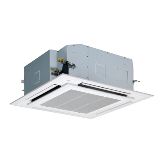
- Page 1 AIR CONDITIONER (MULTI TYPE) Installation Manual Indoor Unit For commercial use Model name: 4-way Cassette Type MMU-UP0091HP-E MMU-UP0121HP-E MMU-UP0151HP-E MMU-UP0181HP-E MMU-UP0241HP-E MMU-UP0271HP-E MMU-UP0301HP-E MMU-UP0361HP-E MMU-UP0481HP-E MMU-UP0561HP-E English...
-
Page 2: Table Of Contents
– 1 – Contents Original instruction Please read this Installation Manual carefully before installing the Air Conditioner. 1 Precautions for safety ..........3 This Manual describes the installation method of the indoor unit. - Page 3 Toshiba Carrier Corporation or, alternatively, he or she has been instructed in such matters by an individual or individuals who have been trained and is thus thoroughly acquainted with the knowledge related to this work.
-
Page 4: Precautions For Safety
– 3 – Precautions for safety Warning indications on the air conditioner unit The manufacturer shall not assume any liability for the damage Warning indication Description caused by not observing the description of this manual. WARNING WARNING WARNING ELECTRICAL SHOCK HAZARD ELECTRICAL SHOCK HAZARD Disconnect all remote Disconnect all remote electric power supplies before servicing. - Page 5 • Do not touch the aluminium fi n of the unit. You may injure • To transport the air conditioner, wear shoes with additional yourself if you do so. If the fi n must be touched for some protective toe caps. reason, fi...
- Page 6 – 5 – • Tighten the fl are nut with a torque wrench in the specifi ed • Install a circuit breaker that meets the specifi cations in the manner. Excessive tighten of the fl are nut may cause a crack in installation manual and the stipulations in the local regulations the fl...
- Page 7 • Upon completion of the installation work, check for refrigerant CAUTION leaks and check the insulation resistance and water drainage. New refrigerant air conditioner installation Then conduct a test run to check that the air conditioner is • This air conditioner adopts the new HFC refrigerant operating properly.
-
Page 8: Accessory Parts
– 7 – Accessory parts Selection of installation place WARNING Accessory parts • Install the air conditioner at enough strong place to withstand the weight of the unit. If the strength is not enough, the unit may fall down resulting in injury. Part name Q’ty Shape... - Page 9 Installation space REQUIREMENT Secure the specified space in the figure for installation and servicing. • When using the air conditioner with 2-way / 3-way discharge system, a strong wind blows directly if the ceiling height is lower than the standard. Model MMU- A mm Therefore, change the setting switch according to height of the ceiling.
-
Page 10: Installation
– 9 – Installation Opening a ceiling and ◆ Treatment of ceiling installation of hanging bolts The ceiling differs according to structure of building. For details, consult your constructor or interior finish REQUIREMENT • Consider the piping / wiring after the unit is hung contractor. - Page 11 ◆ Installation of ceiling opening and Installation of ceiling panel Wireless type Level vial (levelness: 5 mm or less) hanging bolt (Sold separately) Hanging bolt Indoor unit The sensor of indoor unit with wireless remote controller can receive a signal by distance within Hanging bolt Install the ceiling panel according to Installation approx.
-
Page 12: Drain Piping
– 11 – Drain piping Connecting drain pipe Check the draining Connect a hard socket (locally procured) to the hard In the test run, check that water drain is properly For length of the traversing drain pipe, restrict to 20 m socket of the attached supplied flexible hose. -
Page 13: Refrigerant Piping
Refrigerant piping • Test water drain while checking the operation sound of the drain pump motor. (If the operation sound changes from continuous Projection margin in flaring: B (Unit: mm) sound to intermittent sound, water is normally CAUTION drained.) Outer dia. of Conventional R410A tool used After the check, the drain pump motor runs,... -
Page 14: Electrical Connection
– 13 – Electrical connection Airtight test / Air purge, etc. Use the tightening torque levels as listed in the following table. For airtight test, air purge, addition of refrigerant, and Outer dia. of connecting gas leak check, refer to the Installation Manual Tightening torque (N m) WARNING pipe (mm) - Page 15 Power supply <In the case of combining with outdoor units of Super Modular Multi System u series (SMMS-u)> 220-240V ~, 50 Hz Power supply Uv line and Uc line (L2, L3, L4) 0.5 mm² (Up to 500 m) 208-230V ~, 60 Hz Wire size : (2-core shield wire, non-polarity) 0.75 to 1.25 mm²...
- Page 16 – 15 – Remote controller wiring <In the case of combining with outdoor units other than Super Modular Multi System u series (SMMS-u)> 2-core with non-polarity wire is used for wiring of the remote controller wiring and group remote controllers wiring. Control wiring between indoor units, and outdoor unit (L2, L3) Remote controller wiring, remote controller inter-unit (2-core shield wire, non-polarity)
- Page 17 1. Remove the cover of the electrical control box by taking off the mounting screws (2 positions) and pushing the ■ Wiring between indoor unit and outdoor units hooking section. (The cover of the electrical control box remains hanged to the hinge.) 2.
-
Page 18: Applicable Controls
– 17 – Applicable controls Wiring for flow selector unit (sold separately) Connect control wiring and power supply following figure when installing a separately sold Super Heat Recovery ■ Applicable controls setup Multi System. REQUIREMENT (settings at the site) When the air conditioner is used for the first time, it will take some moments after the power has been turned on Remote controller model name: Indoor P.C. - Page 19 Change of lighting time of How to set up swing type Installing indoor unit on high ■ Each time [ ] [ ] setting button is filter sign pushed, indoor unit numbers in the group ceiling The swing type of the louver can be selected. control change cyclically.
-
Page 20: Test Run
– 19 – Test run Group control Electrical control box control. The wireless remote controller is unavailable Refrigerant Before test run for this control. pipe CAUTION For wiring procedure and wiring method of the Do not use the forced test run for cases other than individual line (Identical refrigerant line) system, following procedure. -
Page 21: Maintenance
Maintenance Repeat procedures → → → After the test run, push OFF timer button Indicators “Operation” (green), “Timer” to stop a test run. (green), and “Ready” (orange) in the ([TEST] disappears on the display and the air Cleaning of air filter Use a vacuum cleaner to remove dust from conditioner enters the normal stop mode.) wireless receiver section flash in approx. - Page 22 – 21 – Cleaning of discharge louver Periodic Maintenance For environmental conservation, it is strongly recommended that the indoor and outdoor units of the air conditioner The discharge louver can be removed to clean. in use be cleaned and maintained regularly to ensure efficient operation of the air conditioner. 1.
-
Page 23: Troubleshooting
Troubleshooting Confirmation and check ■ If a problem occurs with the air conditioner, the OFF timer indicator alternately shows the check code and the indoor Unit No. in which the problem occurred. Check code The indoor Unit No. in which the problem occurred. - Page 24 – 23 – Check method On the wired remote controller, central control remote controller and the interface P.C. board of the outdoor unit (I/F), a check display LCD (Remote controller) or 7-segment display (on the outdoor interface P.C. board) to display the operation is provided.
- Page 25 Check code Wireless remote controller Outdoor unit 7-segment display Sensor block display of receiving unit Check code name Judging device Wired remote controller display Auxiliary code Operation Timer Ready Flash 01: TE1 sensor 02: TE2 sensor TE1,TE2 or TE3 sensor trouble 03: TE3 sensor 01: TL1 sensor 02: TL2 sensor...
- Page 26 – 25 – Check code Wireless remote controller Outdoor unit 7-segment display Sensor block display of receiving unit Check code name Judging device Wired remote controller display Auxiliary code Operation Timer Ready Flash – Model mismatch of indoor and outdoor unit –...
- Page 27 Check code Wireless remote controller Outdoor unit 7-segment display Sensor block display of receiving unit Check code name Judging device Wired remote controller display Auxiliary code Operation Timer Ready Flash 01: Comp. 1 side 02: Comp. 2 side IPM short protection trouble Inverter 03: Comp.
-
Page 28: Specifications
– 27 – Specifications Declaration of Conformity Sound power level (dBA) Manufacturer: TOSHIBA CARRIER (THAILAND) CO., LTD. Weight (kg) Model Main unit (Ceiling panel) 144 / 9 Moo 5, Bangkadi Industrial Park, Tivanon Road, Tambol Bangkadi, Cooling Heating Amphur Muang, Pathumthani 12000, Thailand TCF holder: TOSHIBA CARRIER EUROPE S.A.S... - Page 29 Warnings on Refrigerant Leakage Important Check of Concentration Limit The room in which the air conditioner is to be installed requires a design that in the event of refrigerant 2) When there is an effective opening with the adjacent room for ventilation of leaking refrigerant gas (opening gas leaking out, its concentration will not exceed a set limit.
- Page 30 – 29 – 57-EN 58-EN...
- Page 31 144 / 9 Moo 5, Bangkadi Industrial Park, Tivanon Road, Tambol Bangkadi, Amphur Muang, Pathumthani 12000, Thailand 1115350194...