Table of Contents
Advertisement
Advertisement
Table of Contents

Summary of Contents for Pioneer Appli-Pro SLV C500
- Page 1 SLV C500 Super Low Volume Application System Operation Manual APC500-INST 6-15...
- Page 2 ® DECLARATION OF INCORPORATION FOR A PARTIALLY COMPLETED MACHINE: Pioneer Appli-Pro C500 System. MANUFACTURER: Harvest Tec, Inc., 2821 Harvey St, P.O. Box 63, Hudson, WI, 54016, U.S.A. MACHINE DESCRIPTION: An implement mounted machine that applies inoculants to forage crops. DECLARATION OF APPLICATION OF ESSENTIAL REQUIREMENTS OF THE DIRECTIVE 2006/42/ EC OF THE EUROPEAN PARLIAMENT AND OF THE COUNCIL OF 17, MAY, 2006 AND OTHER RELEVANT ®...
-
Page 3: Table Of Contents
Appli-Pro SLV C500 Table of Contents Page Introduction Safety Safety Sign Location Safety Signs Operation for Non-GreenStar Equipped Machines On / Off Botton Select Rate Start / Stop Tons Treated Gauge Pressure Cold Weather Operation Operation for John Deere GreenStar Equipped Machines... -
Page 4: Introduction
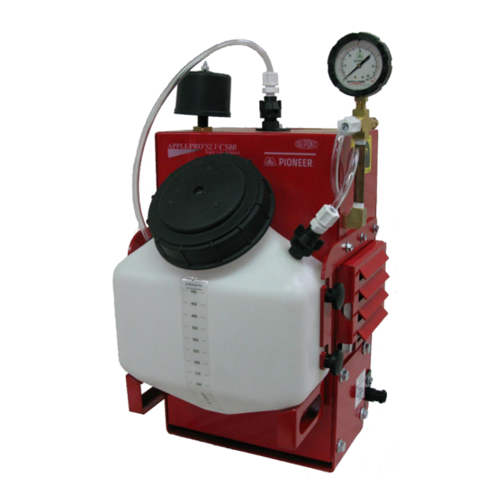
Introduction The Appli-Pro SLV C500 (Super Low Volume Tank Mix) Application System was built for DuPont Pioneer by a leading agricultural manufacturer. The C500 is an integrated system, designed and calibrated specifically ® for Pioneer brand products. This manual will take you through the steps of operation of the applicator and also point out all safety precautions that need to be made while using the applicator. -
Page 5: Safety Signs
Safety Signs Number 1 Spraying hazard. Disconnect power before servicing the applicator Part no. DCL-8003 Number 2 Read and understand the operator’s manual before using or working around the equipment. Part no. DCL-8000 Number 3 Falling hazard. Do Not Step in this area. Part no. -
Page 6: Select Rate
Select Rate This button allows you to select the rate at which you want to apply product. Initially, the display will show 10. This represents the applicator being set to apply for a 10 Ton/Hr harvesting rate. To increase the harvesting rate, press and hold the SELECT/RATE button until the display scrolls to the approximated harvesting rate. -
Page 7: Operation For John Deere Greenstar Equipped Machines
Operation for John Deere GreenStar Equipped Machines Overview The C500 control box has John Deere GreenStar capability. This option allows the C500 to have, “On the Go”, rate adjustments done by the GreenStar system. The GreenStar C500 control has two different operational modes. -
Page 8: Operation Of C500 In (Gs) Mode
Operating the C500 in GreenStar (GS) Mode With the C500 control box in (GS) mode and also hooked into the GreenStar system, it will work as follows: The C500 will automatically adjust the dosing rate according to the throughput signal from the GreenStar System. -
Page 9: Greenstar Diagnostics
GreenStar Diagnostics Testing Communication and Troubleshooting 1. Turn on GreenStar monitor. 2. Turn on SLV Control box and have it operating in GS Mode. (See “SWITCHING BETWEEN OPERATING MODES”) 3. Press “TONS TREATED” button on the SLV control box. 4. GS should appear in the middle of the screen. 5. -
Page 10: Calibration Of C500
Calibration of the C500 Your C500 has been calibrated from the factory at 13.5 volts. Different tractor charging systems, alternators, voltage regulators, bad batteries, or faulty battery cables may affect the output voltage supplied to the C500, which could cause variation in initial calibration. We recommend that if any of these components are replaced during the season, you test and recalibrate your C500. -
Page 11: Application Examples
Example of Over Application Operator is applying at 250 ton per hour and after the test the Tons Treated says 95. Step 1: Fill in the numbers (100) (250) ---------------- ---------------- (95) X (New unknown rate) Step 2: Cross Multiply (100) (250) -----------------... -
Page 12: Routing Service And Maintenance
Routing Service and Maintenance Tools Needed - Metric sockets - Metric wrenches - Philips and flat screwdriver - 1/4 nut driver - Hose cutter - 5/32 & 3/16 Allen wrenches - Pliers - Utility knife - Bleach or OxiClean - Dishwasher soap Maintenance -Daily Maintenance - Flush with clean water for 15 Min. -
Page 13: Cleaning The C500 Tubing
Cleaning the C500 Tubes Some organisms that can be found in well water will grow on the carrier used in Pioneer brand water-soluble inoculant products. The amount of growth is influenced by the amount of bugs in the water, the temperature, and the length of time the bugs are allowed to grow. -
Page 14: Troubleshooting
Faulty wiring, Faulty control box Bad connection to battery Blowing 15 amp in-line fuse Air compressor filters plugged Faulty air compressor During Normal Business Hours After Hours or Weekends Call for Further Assistance 1-877-Pioneer (746-6337), 1-765-437-7211 ext. 82526 or 82280... -
Page 15: Plug Diagrams
Plug Diagrams Control Box (Tower / Control Plug) Pin 1 Blue Communication to GreenStar (Control Box End Only) Pin 2 Compressor/Relay Power Pin 3 Blue Pump Positive Pin 4 Yellow Reversing Relay Pin 5 Not Used Pin 6 Brown Pump Ground Pin 7 Green End of Row (Control Box End Only) -
Page 16: Tower Wire Diagrams
Tower Wiring Diagram... -
Page 17: C500 Parts Breakdown
C500 Parts Breakdown Wiring and Plumbing Ref # Description Part # Wire Harness 006-4524HG 1/4" EVA Tubing 002-9006 20ft Power Harness 006-4640P Jiffy Clip 008-9010 Hose Clamp 003-9002 Filter Bowl 002-4314 Adapter 1/4" MPT x 1/4" HB 003-A1414... -
Page 18: Main Unit
C500 Parts Breakdown Main Unit Ref # Description Part # Filter 002-4522 C500 Enclosure 001-4590 Air Hose 1/2” 002-9000 Box Air Filter 002-4521 Elbow 1/4” MPT x 1/2” HB Brass 003-EL1412B Compressor 007-4530 Compressor Mounts 007-4530M Jaco Fitting 003-JA1414 Tee 1/4” HB x 1/4” HB x 1/4” MPT 003-T1414TB Air Hose 1/4”... -
Page 19: Control Box And Spray Parts
C500 Parts Breakdown Control Box and Spray Parts Ref # Description Part # Jaco Elbow 003-JEL1414F Jaco Nut 003-JN14 Strap 001-4216 Nozzle Body 004-4722 Strainer 004-1203-50 004-TX-10 Nozzle Cap 004-4723 Female Coupler 004-1207H Washer 004-1207W Elbow 1/4” MPT x 1/4” HB 003-EL1414 Control Box 006-4525G... - Page 20 C500 Parts Breakdown Pump and Wiring Ref # Description Part # Jaco Nut 1/8” 003-JN18 Street Elbow 003-SE4514 Tee 1/4” FPT 003-TT14 Adapter 1/4” MPT x 1/4” HB 003-A1414 Female Coupler 004-1207G Jaco Nut 1/4” 003-JN14 Relay to Pump Wire 006-4524Q Reversing Relay 006-2187...
-
Page 21: Intake And Gauge
C500 Parts Breakdown Intake and Gauge Ref # Description Part # Gauge 002-2207P 1/4" Brass Cross 003-C14B Jaco Straight 1/4" HB x 1/4” NPT 003-JA1414 1/4" PVC Tubing 002-9014 Female Quick Connect 004-1207H Washer 004-1207W 1/4" Brass Pipe 4” Long 003-M14BP Pop Off Valve 002-4520... - Page 22 C500 Parts Breakdown Hardware Quantity Item Where used 3/16” Fender Washer Compressor Mount 6/32” x 1/2” Philips Machine Screw Relay 6/32” Nylon Lock Nut Relay 10/32” x 1/2” Philips Machine Screw Injection Pump Mount 10/32 Nylon Lock Nut Injection Pump Mount, Compressor M6 x 16 Flange Bolt Cover, Injection Pump Plate, Bottlehanger “Y”...
- Page 23 Notes:...
- Page 24 * All products are trademarks of their respective manufacturers. PIONEER® brand products are provided subject to the terms and conditions of purchase which are part of the labeling and purchase documents. ® Trademarks and service marks of Pioneer Hi-Bred. © 2008 PHII.