Table of Contents
Advertisement
Quick Links
Advertisement
Table of Contents

Related Manuals for Motorola SE4750


Summary of Contents for Motorola SE4750
- Page 1 SE4750 INTEGRATION GUIDE...
- Page 3 SE4750 INTEGRATION GUIDE 72E-171726-01 Revision A November 2013...
- Page 4 Motorola. No right to copy a licensed program in whole or in part is granted, except as permitted under copyright law. The user shall not modify, merge, or incorporate any form or portion of a licensed program with other program material, create a derivative work from a licensed program, or use a licensed program in a network without written permission from Motorola.
- Page 5 Revision History Changes to the original manual are listed below: Change Date Description -01 Rev A 11/2013 Initial release...
- Page 6 SE4750 Integration Guide...
-
Page 7: Table Of Contents
Notational Conventions ....................x Related Documents....................... x Service Information ....................... xi Chapter 1: Getting Started Introduction ........................1-1 SE4750 ........................1-2 Aiming System ....................... 1-3 Aiming Error ......................1-3 Aiming Control ......................1-3 Illumination System ....................1-3 Illumination Control ....................1-3 Frame Rate Control .................... - Page 8 SE4750 Integration Guide Positioning the Exit Window ..................2-7 Avoiding Scratched Windows .................. 2-7 Window Material ...................... 2-8 Commercially Available Coatings ................2-9 A Word About Coatings ................... 2-9 Optical Path ........................2-10 Imaging Field of View ....................2-10 Aiming Pattern ......................2-11 Imaging and Aiming Parallax ..................
- Page 9 Table of Contents ACQUISITION 0x58 ....................5-5 ACQUISITION_MODE 0x5B .................. 5-5 AIM 0x55 ........................ 5-5 AIM_DURING_EXPOSURE 0x56 ................5-5 AUTO_POWER_REDUCTION 0x74 ..............5-5 EXECUTE_SCRIPT 0x77 ..................5-5 EXTERNAL_ILLUMINATION 0x5A ................ 5-5 GET_EXTENDED_STATUS 0x79 ................. 5-6 GET_PARAM 0x70 ....................5-6 ILLUMINATION_DURING_EXPOSURE 0x59 ............5-6 ILLUMINATION_POWER_LEVEL 0xF0 ..............
- Page 10 SE4750 Integration Guide...
-
Page 11: About This Guide
ABOUT THIS GUIDE Introduction The SE4750 Integration Guide discusses the theory of operation, installation, and specifications of the engine, and how to integrate the engine into data capture devices. NOTE This guide provides general instructions for the installation of the engine into a customer's device. -
Page 12: Notational Conventions
SE4750 Integration Guide Notational Conventions This document uses the following conventions: • Italics are used to highlight chapters and sections in this and related documents • bullets (•) indicate: • Action items • Lists of alternatives • Lists of required steps that are not necessarily sequential •... -
Page 13: Service Information
Software type and version number. Motorola responds to calls by e-mail, telephone or fax within the time limits set forth in support agreements. If your problem cannot be solved by Motorola Solutions support, you may need to return your equipment for servicing and will be given specific directions. - Page 14 SE4750 Integration Guide...
-
Page 15: Chapter 1 Getting Started
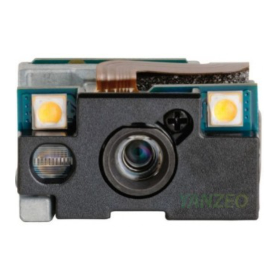
This device emits CDRH/IEC Class 2 laser and IEC Class 1M light. Do not stare into beam. Introduction The SE4750 captures digital images for transmission to a decoder to decode a bar code of any format supported by the decoding software. The SE4750 uses laser aiming and LED illumination. -
Page 16: Se4750
Aiming SE4750 Block Diagram Figure 1-1 A 21-pin ZIF connector on the SE4750 connects the engine and the host device via a 55 mm flex (available from Motorola). For information about this connector, see Figure 4-1 on page 4-3. Also see... -
Page 17: Aiming System
Frame Rate Control The SE4750 outputs images at 54 frames per second by default. When capturing images, use lower frame rates to increase image brightness. The aiming pattern appears to blink when the frame rate is 30 fps or lower. - Page 18 1 - 4 SE4750 Integration Guide...
-
Page 19: Chapter 2 Installation
This results in decode performance degradation and should be avoided. Grounding The chassis is at ground. Isolate the SE4750 and host if installing the engine to a host that is not at ground, or has ground with the potential to inject noise. -
Page 20: Electrostatic Discharge (Esd)
As a protective measure for the laser diode, at extreme temperatures the SE4750 first shuts off the laser and dims illumination (at 68°C chassis temperature). Illumination shuts off at 72°C. As the engine temperature returns to normal levels the laser and illumination power returns to nominal values. - Page 21 Installation 2 - 3 Lumped Capacitance Thermal Model of SE4750 Scan Engine Figure 2-1 Based on this lumped capacitance thermal model and the engine power consumptions (see Table 3-7 on page 3-8), the allowed engine scanning duty cycles can be calculated and plotted for a defined engine chassis...
- Page 22 2 - 4 SE4750 Integration Guide Engine Scanning Duty Cycle in Presentation Mode, Chassis Temperature Limit = 60°C Figure 2-3 Notes: • The plot represents the condition that the engine is in still air and with no heat sink attached, while the air temperature is measured as the ambient temperature.
-
Page 23: External Optics (Imaging Lens, Illumination Leds, And Aiming Element)
External Optics (Imaging Lens, Illumination LEDs, and Aiming Element) Do not subject external optical components on the SE4750 engine to any external force. Do not hold the engine by an external optical component. This can place excessive stress in the mechanical joints that secure the components, which can cause failures such as joint cracking or breaking. -
Page 24: Mounting
2-4). The SE4750 can be mounted in any orientation without degradation in performance. NOTE Mounting the SE4750 in a non-upright position results in images rotated accordingly in snapshot or video mode. When installing the mounting screws, ensure they do not protrude past the mounting hole threads in the chassis;... -
Page 25: Housing Design
Consider using baffles or matte-finished dark internal housing colors. Optical The SE4750 uses a sophisticated optical system that provides imaging performance that matches or exceeds the performance of much larger imagers. However, an improperly designed enclosure, or improper selection of window material, can affect the performance of the SE4750. -
Page 26: Window Material
2 - 8 SE4750 Integration Guide Window Material Many window materials that look clear can contain stresses and distortions that reduce performance. For this reason, use only cell-cast plastics or optical glass (with or without an anti reflection coating, depending on the application). -
Page 27: Commercially Available Coatings
Installation 2 - 9 Commercially Available Coatings Anti-Reflection Coatings Anti-reflection coatings can be used for stray light control or to achieve maximum working range, and can be applied to the inside and/or outside of the window to reduce the amount of light reflected off the window back into the engine. -
Page 28: Optical Path
2 - 10 SE4750 Integration Guide Optical Path Imaging Field of View SE4750-SR LSR AIM Optical Path - Imaging Field of View Figure 2-5... -
Page 29: Aiming Pattern
Installation 2 - 11 Aiming Pattern SE4750-SR LSR AIM Optical Path - Aiming Pattern Figure 2-6... -
Page 30: Imaging And Aiming Parallax
2 - 12 SE4750 Integration Guide Imaging and Aiming Parallax Due to parallax, the aiming dot is located at the center of the image at 203.2 mm (8.0 inches). SE4750-SR LSR AIM Optical Path - Imaging and Aiming Parallax Figure 2-7... -
Page 31: Engine Clear Aperture
Installation 2 - 13 Engine Clear Aperture SE4750-SR LSR AIM Engine Clear Aperture Figure 2-8 Engine Clear Aperture Notes Obstructing the engine clear aperture can result in one or more of the following effects: • A captured image with non-uniformly illuminated areas. -
Page 32: Recommended Exit Window Information
2 - 14 SE4750 Integration Guide Recommended Exit Window Information Maximum Distance “a” for a Parallel Window (all dimensions in mm) Uncoated window: a < = 1.69 - (t/n) Single side coated window (coated side toward engine): a < = 1.94 - (t/n) Double side coated window: a <... -
Page 33: Engine Stray Light Zone
Installation 2 - 15 Engine Stray Light Zone SE4750-SR LSR AIM Engine Stray Light Zone Figure 2-10 Engine Stray Light Zone Notes Due to high illumination intensity certain objects in the defined stray light zone can reflect light back onto the engine creating blemishes in the image. -
Page 34: Parallel Window Integration Examples
The engine clear aperture is unobstructed. The engine clear aperture is unobstructed. Housing features which are inside of the stray light Housing features are outside of the stray light zone. zone have black matte surfaces. SE4750-SR LSR AIM Parallel Window Integration Examples Figure 2-11... -
Page 35: Tilted Window Integration Examples
Housing features which are inside of the stray light zone. light zone have black matte surfaces. Example 3 The engine clear aperture is unobstructed. A baffle feature with black matte surfaces prevents light from reaching other housing features. SE4750-SR LSR AIM Tilted Window Integration Examples Figure 2-12... - Page 36 2 - 18 SE4750 Integration Guide...
-
Page 37: Chapter 3 Specifications
CHAPTER 3 SPECIFICATIONS Introduction This chapter provides the technical specifications of the SE4750, including electrical characteristics, engine technical specifications, decode zone, and exit window characteristics. Electrical Characteristics Power, MIPI and Parallel Host Interface Power, MIPI and Parallel Host Interface Table 3-1... -
Page 38: I2C, Mipi, And Parallel Host Interface
3 - 2 SE4750 Integration Guide C, MIPI, and Parallel Host Interface I2C_CLK, I2C_DATA Signals Table 3-2 Symbol Parameter Condition Minimum Maximum Units Output Low 3mA sink Voltage VDD_IO_HOST=3.3 3mA sink VDD_IO_HOST=1.8 0.2*VDD_IO_HOST 6mA sink Input High 0.7*VDD_IO_HOST VDD_IO_HOST+0.5 Voltage Input Low -0.5... - Page 39 Specifications 3 - 3 Parallel Host Interface for HSYNC, VSYNC, PIXCLK, and PIX_DATA_x Signals Parallel Host Interface for HSYNC, VSYNC, PIXCLK, and PIX_DATA_0 Through PIX_DATA_7 Signals Table 3-4 Symbol Parameter Conditions Minimum Maximum Units Output High VDD_IO_HOST=3.3 VDD_IO_HOST-0.2 Voltage VDD_IO_HOST-0.45 VDD_IO_HOST=1.8 =8mA Output Low...
-
Page 40: Mipi Host Interface
3 - 4 SE4750 Integration Guide MIPI Host Interface T-LPX T-CLK_PREPARE + T-CLK_ZERO T-CLK_PRE T-HS_PREPARE+ T-HS_ZERO V-LPOH V-OD FRAME START V-CMTX T-HS_TRAIL MIPI Host Interface Table 3-5 Parameter Description Typical Units T-LPX Transmitted length of any low power state period. - Page 41 Specifications 3 - 5 MIPI Host Interface (Continued) Table 3-5 Parameter Description Typical Units V-LP0H LP output high level. V-CMTX HS transmit static common mode voltage. V-OD HS transmit differential voltage.
-
Page 42: Technical Specifications
3 - 6 SE4750 Integration Guide Technical Specifications SE4750 Technical Specifications Table 3-6 Item Description Power Requirements - Input Voltage VCC: 3.3V +/- 0.3V Supply Currents VCC = VCC_ILLUM: 3.0V to 5.5V VCC_ILLUM = VDD_IO_HOST = 3.3V VDD_IO_HOST 1.7 to 3.6... - Page 43 8.0 grams (0.28 oz) Electrical Interface 21 pin 0.3 mm pitch ZIF connector Chapter 4, Electrical Interface for more information. NOTE Environmental and/or tolerance parameters are not cumulative. Motorola recommends a thermal analysis if the application is subject to an extreme temperature environment.
-
Page 44: Supply Currents Vcc = Vcc_Illum = Vdd_Io_Host = 3.3V @ 23C
3 - 8 SE4750 Integration Guide Supply Currents VCC = VCC_ILLUM = VDD_IO_HOST = 3.3V @ 23C Parallel and MIPI Host Interface with Laser Aim (Engine Only without PL3307 Decoder) Parallel and MIPI Host Interface with Laser Aim; Current (mA) Flowing into Power Domains @ 23... -
Page 45: Sample Current Scope Plots
Specifications 3 - 9 Sample Current Scope Plots Total Current (VCC_ILLUM + VCC + VDD_IO_HOST) Figure 3-1 VCC Current Figure 3-2... - Page 46 3 - 10 SE4750 Integration Guide VCC_ILLUM Current Figure 3-3 VDD_IO Host Current (Parallel Version) Figure 3-4...
-
Page 47: Skew, Pitch, And Roll
Specifications 3 - 11 Skew, Pitch, and Roll Measured on a 20 mil Code 39 symbol at a distance of 5 inches. Tolerance for skew and pitch is reduced at extreme ends of the working range. Skew Pitch + 60° from normal + 60°... -
Page 48: Decode Ranges
3 - 12 SE4750 Integration Guide Decode Ranges SE4750-SR Decode Distances Table 3-8 Near Distance Far Distance Bar Code Type (in, typical) (in, typical) 3 mil Code 39 5 mil Code 128 5 mil PDF417 6.67mil PDF417 10.6 10 mil Data Matrix 10.6... -
Page 49: Chapter 4 Electrical Interface
CHAPTER 4 ELECTRICAL INTERFACE Introduction Table 4-1 lists the pins and signals of the 21-pin connector on the SE4750. See Figure 2-4 on page 2-6 for the pin 1 location on the rear of the engine, on the side opposite the aiming/illumination system. - Page 50 4 - 2 SE4750 Integration Guide SE4750 Parallel Host Interface Signal Information (Continued) Table 4-1 Pin Number SE4750 Signal Name Notes VCC_ILLUM PWR In Illumination power HSYNC Horizontal sync Ground PIXCLK Sensor pixel clock Ground SE4750 MIPI Host Interface Signal Information...
-
Page 51: Connector Drawings
Electrical Interface 4 - 3 Connector Drawings For detailed connector information, refer to the manufacturer's specifications: Kyocera 6283 Series. No. of Position 6.0 mm 8.3 mm 6.7 mm 21-Pin ZIF Connector (SE4750 Engine to Flex), Kyocera 6283 Series Figure 4-1... - Page 52 4 - 4 SE4750 Integration Guide MIPI Host Flex, p/n 15-162392-xx Figure 4-2...
- Page 53 Electrical Interface 4 - 5 Parallel Host Flex, p/n 15-171522-xx Figure 4-3...
-
Page 54: Power Supply Sequencing
4 - 6 SE4750 Integration Guide Power Supply Sequencing The imager engine contains three power domains: VCC, VCC_ILLUM, and VDD_IO_HOST. Specific power-up and power-down sequences of these three supplies are recommended to ensure proper operation. Power-up During power-up, the VCC supply ramps up before or at the same time as the VCC_ILLUM and VCC_IO_HOST supplies. -
Page 55: Chapter 5 Control Interface
0x55 Turns the aim pattern on and off. AIM_DURING_EXPOSURE 0x56 Captures the aim pattern in the image. AUTO_POWER_REDUCTION 0x74 Places the SE4750 in a low power state when idle. ENTER_BOOTLOADER 0x91 Enters bootloader mode. EXECUTE_SCRIPT 0x77 Executes a programmed script. - Page 56 Reads the Aptina AR0134 registers. RESET 0x57 Returns engine components to a default state. TIME_TO_LOW_POWER 0x75 Sets the length of time the SE4750 is idle before entering low power mode. WR_SCRIPT 0x76 Programs more than one SE4750 command into one script.
-
Page 57: Transactions
C is a master/slave protocol, meaning the host initiates both transmissions. The SE4750 typically processes a command in less than 1 ms, but some commands take up to 100 ms. For this reason, after sending a command, the host (I C master) should request a response, and if the SE4750 does not respond the host should retry the response request for up to 100 ms. -
Page 58: Command Checksum
5 - 4 SE4750 Integration Guide Command Checksum Every command must include a checksum, calculated as follows: Sum the bytes in the command, starting from the opcode through the last command data byte. Use only the low byte of this result. -
Page 59: Command Descriptions
After receiving the Stop command, the SE4750 may not respond to subsequent commands for up to one frame time (16.6 ms at 60 fps) because the system requires the current frame to complete before the engine processes new commands. -
Page 60: Get_Extended_Status 0X79
SE4750 Integration Guide GET_EXTENDED_STATUS 0x79 The SE4750 internally tracks various operating states and stores these states in the extended status structure. This command gets these states from the SE4750. The following are the operating conditions and descriptions. Each operating condition has 2 bits in the extended status: •... -
Page 61: Image_Capture_Mode 0X73
Use this command for test purposes to verify that the engine is in a powered state. POWER_MODE 0x5F Changes the SE4750’s power mode. Although this command offers a Full Power mode option, any command returns the SE4750 to full power mode. -
Page 62: Rd_Sensor 0X51
RESET 0x57 Returns the SE4750 to a default state. TIME_TO_LOW_POWER 0x75 Sets the length of time the SE4750 must be idle before it enters low power mode. This only applies if AUTO_POWER_REDUCTION is enabled. WR_SCRIPT 0x76 Programs more than one SE4750 command into a script, which can be executed using a single command (EXECUTE_SCRIPT). -
Page 63: Command / Response Formats
SE4750 commands. In the columns SE4750 Command Data and SE4750 Response Data, the following letters identify the size of the data: (B) = Byte, (W) = Word, or (A) = Array. Words are in Little-Endian format (low byte first). - Page 64 5 - 10 SE4750 Integration Guide SE4750 Command and Response Formats (Continued) Table 5-3 SE4750 Command SE4750 Response Function SE4750 Response Note1 SE4750 Command Data Note2 Data POWER_MODE 0x5F 0x5F 0x00=Full* 0x01=Low ILLUMINATION_POWER_LEVEL 0xF0 0xF0 Lowest = 1 Highest Power Level = 18...
- Page 65 Control Interface 5 - 11 SE4750 Parameter Numbers and Data Formats Table 5-4 Length Parameter Description Number (bytes) MODEL_NUMBER Engine model number SERIAL_NUMBER Engine serial number DATE_MANUFACTURE Engine manufacturing date DATE_SERVICE Engine service date SCANNER_BOOTLOADER_FIRMWARE_VERSION Engine bootloader version SCANNER_PRODUCTCODE_FIRMWARE_VERSION Engine firmware version...
- Page 66 5 - 12 SE4750 Integration Guide...
-
Page 67: Chapter 6 Application Notes
Introduction This chapter includes image acquisition and power consumption information. LED illumination is required for decoding. Image Acquisition The SE4750 contains a 1280 H x 960 V CMOS sensor. Figure 6-1 illustrates pixel output format, and Figure 6-2 Figure 6-3... -
Page 68: Output Data Format
6 - 2 SE4750 Integration Guide Output Data Format Image data can be read out in a progressive scan. Vertical and horizontal blanking surrounds valid image data, as shown in Figure 6-1........P 00 00 00 ....00 00 00 0,n-1 ........P... - Page 69 Application Notes 6 - 3 Frame Time @74.25 MHz Table 6-1 Parameter Description Pixel Clock Time Units Active data time 1280 17.23 µs With stats enabled 1360 18.31 µs Frame start blanking 0.08 µs Frame end blanking 0.08 µs Horizontal blanking 1.45 µs With stats enabled...
-
Page 70: Recommended Procedures
Recommended Procedures The following trigger mode procedures describe the recommended transaction sequence between a host and the SE4750. These transaction sequences use discrete commands for clarity. Replace any set of discrete commands with a multi-command EXECUTE_SCRIPT to improve throughput. Normal Decode Mode... - Page 71 The host sends the Aim On command. • The host sends the Acquisition Start command. • The SE4750 begins outputting images. Starting with the first frame, every 60th frame is a picklist frame (1,61,121,181 …). • The host attempts to decode the images.
- Page 72 The SE4750 optimizes the image output for motion detection. During this mode: • The SE4750 does not automatically enter standby or low power mode. • The host uses the Power Mode command to put the SE4750 into a low power mode (for support of Bus Powered USB).
- Page 73 The SE4750 optimizes the image output for motion detection. During this mode: • The SE4750 does not automatically enter low power mode. • The host uses the Power Mode command to put the SE4750 into a low power mode (for support of Bus Powered USB).
- Page 74 The SE4750 optimizes the image output for motion detection. During this mode: • The SE4750 does not automatically enter low power mode. • The host uses the Power Mode command to put the SE4750 into a low power mode (for support of Bus Powered USB).
-
Page 75: Snapshot Mode
Upon a trigger pull: • The host sends the Illumination On command. • The SE4750, if in low power mode, exits low power mode (either Reduced or Sleep). • The host sends the Aim On command. • The host sends the Acquisition Start command. -
Page 76: Video Mode
Upon a trigger pull: • The host sends the Illumination On command. • The SE4750, if in low power mode, exits low power mode (either Reduced or Sleep). • The host sends the Aim On command. • The host sends the Acquisition Start command. -
Page 77: Appendix A Register Settings
APPENDIX A REGISTER SETTINGS For information on register settings for the engine, refer to the Aptina AR0134 1/3” 1.2 Mp CMOS Digital Image Sensor Datasheet, available at http://www.aptina.com. - Page 78 A - 2 SE4750 Integration Guide...
- Page 79 INDEX command list ......5-1 data formats ......5-11 aiming .
- Page 80 Index - 2 SE4750 Integration Guide MIPI, parallel hosts, EXT_ILLUM_EN signal . . . 3-2 positioning exit window ....2-7 parallel host ......3-3 thermal considerations .
- Page 81 Index - 3 script recommendations ..... 6-10 service information ......xi shock specification .
- Page 82 Index - 4 SE4750 Integration Guide...
- Page 83 We’d like to know what you think about this Manual. Please take a moment to fill out this questionnaire and fax this form to: (631) 627-7184, or mail to: Motorola Solutions, Inc. One Motorola Plaza M/S B-10 Holtsville, NY 11742-1300 Attention: Technical Publications Manager Data Capture Solutions IMPORTANT: If you need product support, please call the appropriate customer support number provided.
- Page 86 MOTOROLA, MOTO, MOTOROLA SOLUTIONS and the Stylized M Logo are trademarks or registered trademarks of Motorola Trademark Holdings, LLC and are used under license. All other trademarks are the property of their respective owners. © 2013 Motorola Solutions, Inc. All Rights Reserved.