Advertisement
Quick Links
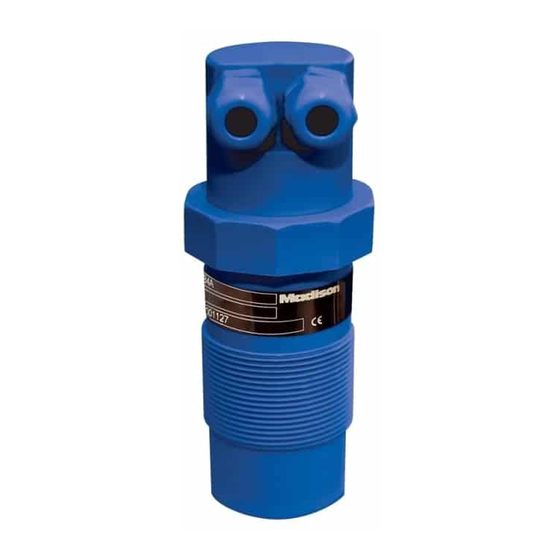
U5098
ultrasonic level transmitter
Sensing Solutions since 1959
U5098 MODBUS RTU
Software download link:
madisonco.com/U5098software
View in-stock products ready to ship today at Madisonco.com/buy
Madison Company, Inc.
27 Business Park Drive
Branford, CT 06405
U5098 Series Ultrasonic Sensors Manual
099-MF179
technical documentation EN Rev. B
© 2020 Madison Company, Inc., MAD_MAN_099-MF179_RevA_060920
ECN #11618, Effective Date 06/09/2020, 099-MF179 Rev. A
203-488-4477 or 800-466-5383
info@madisonco.com
www.madisonco.com
MADE IN THE USA
Made in the USA
Advertisement

Related Manuals for Madison U5098 Series

Summary of Contents for Madison U5098 Series
- Page 1 U5098 U5098 Series Ultrasonic Sensors Manual ultrasonic level transmitter 099-MF179 Sensing Solutions since 1959 U5098 MODBUS RTU Software download link: madisonco.com/U5098software technical documentation EN Rev. B View in-stock products ready to ship today at Madisonco.com/buy Madison Company, Inc. 203-488-4477 or 800-466-5383 27 Business Park Drive info@madisonco.com...
-
Page 2: Table Of Contents
U5098 Series Ultrasonic Sensors Manual 099-MF179 - Manual Contents U5098 - conte CONTENTS page. 3 1-WARRANTY 2-PRODUCT page. 4 3-PERFORMANCE SPECIFICATIONS page. 5 4-DIMENSIONS page. 6 5-INSTALLATION page. 7 6-ELECTRICAL CONNECTIONS page. 11 page. 12 7-CONFIGURATION MODES page. 15 8-OPERATOR INTERFACE page. -
Page 3: Madison Company, Inc
099-MF179 - Warranty U5098 - warranty WARRANTY Products supplied by Madison are guaranteed for a period of 12 (twelve) months from delivery date according to the conditions specified in our sale conditions document. Madison can choose to repair or replace the Product. -
Page 4: Branford, Ct 06405
U5098 Series Ultrasonic Sensors Manual 099-MF179 - Features U5098 - features PRODUCT 1. Dual M16 x 1.5 Conduit 2. Sensor head Þxing nut 3. Fixing nut 4. Sensor IDENTIFICATION Each sensor has an adhesive identification plate on which are indicated the sensor's main data. The information on the identification plate is as follows:. - Page 5 U5098 Series Ultrasonic Sensors Manual U5098 - featu 099-MF179 - Specifications FEATURES Housing/sensor material Polypropylene Mechanical installation G 2” (Fits 2” NPT) Protection degree IP66 Electrical connection Screw Terminals Working temperature -22 to 158°F (-30 to 70°C) Pressure Max 7.25 PSI (0.5 bar)
- Page 6 U5098 - dimensions U5098 Series Ultrasonic Sensors Manual 4-DIMENSIONS 099-MF179 - Dimensions 2 LIQUID TIGHT M16x1.5 2 FIXING NUT 2" G 2” Ø2.19 Madison Company, Inc. 203-488-4477 or 800-466-5383 27 Business Park Drive info@madisonco.com Branford, CT 06405 www.madisonco.com MADE IN THE USA Made in the USA ©...
- Page 7 U5098 Series Ultrasonic Sensors Manual U5098 - installation 099-MF179 - Installation INSTALLATION MOUNTING PRECAUTIONS Mounting position - With cambered roof, do not install the sensor in the tank center (b). Leave a 11” (300mm) (d) minimum distance between the sensor and the tank smooth wall.
- Page 8 U5098 Series Ultrasonic Sensors Manual 099-MF179 - Installation U5098 - installation Installation in nozzle In case of nozzle installation, make sure the sensor bottom protrudes at least 0.39” (10mm) from the bottom of the nozzle. ≥ 0.39” (10mm) U5098 can be installed in an extension pipe to turn away the sensor from the maximum level point.
- Page 9 U5098 Series Ultrasonic Sensors Manual 099-MF179 - Installation U5098 - installation Reference pipe installation Disturbing factors that may inßuence the level measurement in liquids, as for example: - foam presence on the liquid surface - internal structures presence in the tank - presence of ßoating bodies on the liquid surface...
- Page 10 U5098 Series Ultrasonic Sensors Manual 099-MF179 - Installation U5098 - installation Agitators presence Level measurement when using agitators in the tank is possible due to the auto-tuned statistical filter. Adjustment of the filter settings is rarely needed, but if required, the U5098 sensor programming parameters may be edited as follows in the MODBUS RTU Software: FILTER;...
-
Page 11: 6-Electrical Connections
U5098 Series Ultrasonic Sensors Manual 099-MF179 - Electrical Connections U5098 - electrical connections ELECTRICAL CONNECTIONS IP66 CONNECTIONS 1) We recommend the use of PVC jacketed 24 AWG cable for connection. 2) Open the cap by unscrewing the nut. 3) Lead the cables into the transmitter through the glands... -
Page 12: 7-Configuration Modes
U5098 Series Ultrasonic Sensors Manual 099-MF179 - Electrical Connections/Configuration Modes U5098 - electrical connections / conÞ guration modes HUMIDITY INFILTRATIONS To avoid the humidity inÞltration inside the housing is recommended: - to use a cable with a 0.2”-0.4” (5-10mm) outer diameter and fully tighten the M16 cable gland for electrical... - Page 13 U5098 Series Ultrasonic Sensors Manual Manual 099-MF179 - Configuration Modes U5098 - conÞ guration modes VIA 2 BUTTONS CALIBRATIONS U5098 has 2 buttons on board, P1 and P2, with which it is possible: - to program the level measurement range via the 4mA and 20mA distances self-acquisition - to program the RL1 and RL2 thresholds via the switching distances self-acquisition.
- Page 14 U5098 Series Ultrasonic Sensors Manual U5098 - conÞ guration modes 099-MF179 - Configuration Modes RL1 MAX LEVEL THRESHOLD DISTANCE To set the RL1 maximum level alarm threshold is necessary that the real level is the one corresponding to the ÒRL1 max. lev. threshold dist.Ó; alternatively it is possible to place a target orthogonally to the U5098 transmitter at a distance equivalent.
-
Page 15: Made In The Usa
U5098 Series Ultrasonic Sensors Manual 099-MF179 - Configuration Modes U5098 - conÞ guration modes RL1 PUMP SET UP (only for RL1) A pump control functioning activation, with hysteresis, is possible two thresholds setting is required: upper and lower threshold. - UPPER. - Page 16 U5098 Series Ultrasonic Sensors Manual U5098 - conÞ guration modes 099-MF179 - Configuration Modes Additional MODBUS RTU Software settings: MEDIUM Madison Company, Inc. 203-488-4477 or 800-466-5383 27 Business Park Drive info@madisonco.com Branford, CT 06405 www.madisonco.com Made in the USA © 2020 Madison Company, Inc., MAD_MAN_099-MF179_RevA_060920...
- Page 17 U5098 Series Ultrasonic Sensors Manual U5098 - conÞ guration modes 099-MF179 - Configuration Modes Additional MODBUS RTU Software settings: FILTER COEEFICIENT Input a value from 1 to 99. maximum speed, 99 maximum slowness. The function is deactivated with 0 (immediate response).