Advertisement
Quick Links
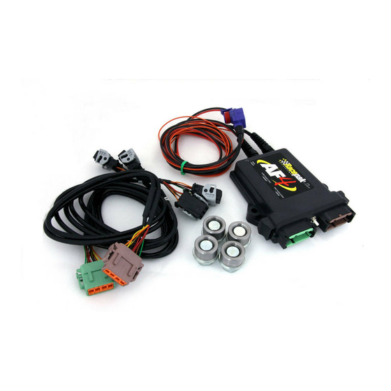
Four Channel Bosch LSU4 Wide Band UEGO Controller
Module Type: AF_MODULE
Output Units:
Lambda
Channel #1:
Channel Name: A/F Cyl 1
Sample Rate: 50/sec
Channel #3:
Channel Name: A/F Cyl 5
Sample Rate: 50/sec
Module Installation:
Mount the controller in a location that does not expose the module to excessive heat, moisture and vibration. Plug
the blue connector in to your data loggers V-Net system. This module is compatible with all V-Series data loggers
except the V50 record/playback module.
WIRE COLOR
WIRE FUNCTION
12V TO 18V MAIN
RED WIRE
SUPPLY POWER
MAIN SUPPLY
BLACK
GROUND
SWITCHED
ORANGE
POWER
are running. This requires that you make certain all of your power and ground connections are solid and all wiring is
at least 16 gauge. Connect the black wire to a solid chassis ground and the red wire to constant 12-18 volt power.
It is highly recommended that you connect the red wire power on the switched side of the vehicles master power
safety switch. Do not run the main power wires (red and black) through an on/off switch. Connect the orange wire
to switched 12-18 volt power to turn on/off the main power to the AF4 controller. The air fuel controller and sensor
heaters will turn on when power is applied to the orange wire.
IMPORTANT!!
The sensor heaters will turn on and draw up to 6-8 amps of current anytime the power is applied to the
orange wire.
Sensor Installation
We recommend installing the sensors in individual cylinder tubes. Mounting the sensor in the collector is not
recommended since oxygen can pass back over the sensor during overlap causing lean readings, particularly at low
engine RPM. Weld the sensor bung approximately 12 inches from the header flange. Mounting the sensor too close
to the exhaust valve can cause the sensor to overheat. To avoid sensor damage from condensation, do not mount the
sensor on the bottom of the exhaust tube. Each sensor has been calibrated at the factory to a specific channel in the
controller. Plug each sensor into the appropriate wire harness according to the label on each sensor. If the sensors
get mixed up or you need to replace a sensor, you will need to recalibrate the controller as described later in this
manual.Each cable will be labeled with the intended cylinder number.
IMPORTANT!!
Do not run the motor for an extended period of time without having the power turned on to the controller.
Running the motor without the sensor heater turned on can damage the sensor. If you are not using the
sensors remove them from the pipe and use the plug provided with each sensor.
Part Number 220-VM-AF4-1357
Module Configuration Setup:
Serial Number: 849-852
A/F Gasoline
A/F Methanol
Channel #2:
Channel Name: A/F Cyl 3
Sample Rate: 50/sec
Channel #4:
Channel Name: A/F Cyl 7
Sample Rate: 50/sec
MINIMUM WIRE
GAUGE REQ.
16
16
none
__________________
Heater Power Connection
The red and black wires, exiting the rear of
the housing, supplies the main power for the
sensor heaters and controller once they are
switched on. The orange wire, exiting the rear
of the housing, turns on the power for the
sensor heaters and controller. The controller
can draw up to 6-8 amps when all four heaters
Advertisement

Related Manuals for Bosch LSU4


Summary of Contents for Bosch LSU4
- Page 1 Four Channel Bosch LSU4 Wide Band UEGO Controller Part Number 220-VM-AF4-1357 Module Configuration Setup: Module Type: AF_MODULE Serial Number: 849-852 Output Units: Lambda A/F Gasoline A/F Methanol __________________ Channel #1: Channel #2: Channel Name: A/F Cyl 1 Channel Name: A/F Cyl 3...
- Page 2 Software Setup and Module Configuration You must have DataLink II version 3.0a or higher installed in your PC. This module has been factory configured as described in the setup box located at the top of this page. If you purchased this module as an upgrade to an existing system, you will need to update your car configuration file before you will be able to access the information from this module.
- Page 3 Setting the Sensor Type: This module can be programmed to output the air/fuel ratio in the following units. Lambda (fuel independent) AFR for gasoline AFR for methanol Custom units (use for fuels not listed) To change the output units, left click on the drop down arrow button next the the box labeled ‘Sensor’ then make your selections.
-
Page 4: Operation
Operation: The sensor heaters require approximately 45 seconds to warm-up. You must turn the power on to the controller early enough that the sensors have time to warm-up. While the sensors are warming up they will output a data value of –0.10. -
Page 5: Troubleshooting
The status of the A/F channel will be displayed at the bottom of the dialog box. Before performing a calibration, make sure the sensor is not still warming up and that there are no errors. Do not use the Heater Calibration, Restart or Zero Calibration buttons.