Table of Contents
Advertisement
Advertisement
Table of Contents

Related Manuals for Cisco Catalyst Micro Series


Summary of Contents for Cisco Catalyst Micro Series
- Page 1 Cisco Catalyst Micro Series Switch Hardware Installation Guide First Published: 2021-02-23 Americas Headquarters Cisco Systems, Inc. 170 West Tasman Drive San Jose, CA 95134-1706 http://www.cisco.com Tel: 408 526-4000 800 553-NETS (6387) Fax: 408 527-0883...
-
Page 2: Table Of Contents
How to Mount the Switch on a Rapid 45 Duct How to Mount the Switch in a Cable Duct with Mounting Box How to Mount the Switch in a Cable Duct with Anchor Rail Cisco Catalyst Micro Series Switch Hardware Installation Guide... - Page 3 Speed, Duplex, and Autonegotiation Autonegotiation and Network Interface Cards Cabling Distance Finding the Switch Serial Number A P P E N D I X A Technical Specifications Physical Specifications Environmental Specifications Power Adapter Specifications Cisco Catalyst Micro Series Switch Hardware Installation Guide...
- Page 4 Contents Cisco Catalyst Micro Series Switch Hardware Installation Guide...
-
Page 5: Product Overview
C H A P T E R Product Overview Cisco Catalyst Micro Series switch is a small form factor micro switch designed to provide networking solutions for decentralized networking. The Cisco Catalyst Micro Series family of switches is ideal for FTTx deployments. -
Page 6: Physical Components
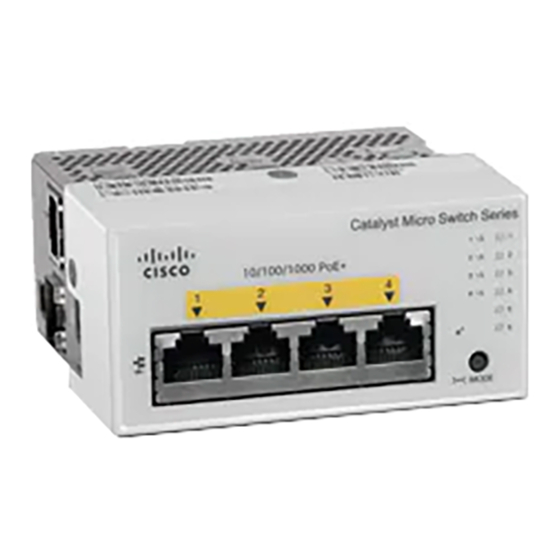
Product Overview Physical Components Physical Components This section identifies the physical components that constitute the Cisco Catalyst Micro Series Switches. Figure 1: Detailed Architecture of a CMICR-4PS Switch Four 1 G PoE+ downlink ports Power adapter slot Mode button Micro USB console port... -
Page 7: Hardware Features
802.3at and also provide PoE support for end points such as access points, IP camera or surveillance systems, Cisco IP Phones and so on. The PoE switch ports are Power Source equipment (PSE) capable and source Cisco Catalyst Micro Series Switch Hardware Installation Guide... -
Page 8: Console Ports
You can order an adapter with the switch, or you can order it later from your Cisco representative. The following are the power adapters supported by Cisco Catalyst Micro Series switches. -
Page 9: Leds
Activity. Port is sending or receiving data. Blinking green-amber Link fault. Error frames can affect connectivity, and errors such as excessive collisions, CRC errors, and alignment and jabber errors are monitored for link faults. Cisco Catalyst Micro Series Switch Hardware Installation Guide... -
Page 10: Downlink Port Poe Leds
After a port is reconfigured, the port LED is amber for up to 30 seconds as STP searches for loops. System LED Color System Status System is not powered on. Green System is operating normally. Cisco Catalyst Micro Series Switch Hardware Installation Guide... -
Page 11: Usb-C Led
In Cisco Catalyst Micro Series Switches, LEDs are normally turned off to save power. When the mode button is pressed, the LEDs turn on for a set period of 60 seconds before they turn off again to save power. This can be overridden by a configuration parameter which alters the default 60 second timeout or disables LED power savings completely. - Page 12 Product Overview Mode Button Cisco Catalyst Micro Series Switch Hardware Installation Guide...
-
Page 13: Switch Installation
Do not disconnect connections to this equipment unless power has been removed or you have verified that the area is nonhazardous. Secure any external connections that mate to this equipment by using screws, sliding latches, threaded connectors, or other means provided with this product.Statement 1062 Cisco Catalyst Micro Series Switch Hardware Installation Guide... -
Page 14: Contents Of The Shipping Box
Some components are optional. To install the switch, you will need to order mounting accessories depending on the mounting option that you choose. You can order them when you order your switch, or you can order them later from your Cisco representative. - Page 15 CMICR-4PS or CMICR-4PC switch of (Optional) Bezel short centered Cisco Catalyst Micro Series Switches Pointer Card (Optional) Bezel short off centered (Optional) AC power adapter and power (Optional) Bracket short off centered cord Cisco Catalyst Micro Series Switch Hardware Installation Guide...
-
Page 16: Installation Guidelines
Installation Guidelines Supported Hardware • Up to 1 GB of Cisco SD memory card is supported. • USB to UART device driver from the Silicon Labs website. Download the device driver depending on the operating system installed. General Guidelines When determining where to install the switch, verify that these guidelines are met: •... -
Page 17: How To Mount The Switch On A Rapid 45 Duct
Cut the front cover of the duct on both sides to make an opening corresponding to the width of the switch. Step 2 Align and insert the switch in to the opening in the duct such that the four lancing features locks into the opening on the duct. Cisco Catalyst Micro Series Switch Hardware Installation Guide... - Page 18 Switch Installation How to Mount the Switch on a Rapid 45 Duct Rapid 45 Duct (OBO Bettermann Switch GK-53100LGR/6113002) Cisco Catalyst Micro Series Switch Hardware Installation Guide...
-
Page 19: How To Mount The Switch In A Cable Duct With Mounting Box
Figure 6: Switch Mounted on a Rapid 45 Duct How to Mount the Switch in a Cable Duct with Mounting Box Before you begin Ensure you have the following accessories available before starting the installation. Cisco Catalyst Micro Series Switch Hardware Installation Guide... - Page 20 Procedure Step 1 Assemble the mounting box into the duct. Ensure that the clips on the mounting box snaps into the profile on the duct thereby locking the box into the duct. Cisco Catalyst Micro Series Switch Hardware Installation Guide...
- Page 21 How to Mount the Switch in a Cable Duct with Mounting Box Step 2 Position the mounting bracket such that the screw holes on it are aligned to the screw holes on the mounting box. Cisco Catalyst Micro Series Switch Hardware Installation Guide...
- Page 22 How to Mount the Switch in a Cable Duct with Mounting Box Step 3 Slide the bracket to the right and fasten the four flat head screws to fix the bracket to the mounting box. Cisco Catalyst Micro Series Switch Hardware Installation Guide...
- Page 23 How to Mount the Switch in a Cable Duct with Mounting Box Step 4 Unscrew the locking plate on the mounting bracket and rotate it by 90 degrees clockwise to make enough space to install the switch. Cisco Catalyst Micro Series Switch Hardware Installation Guide...
- Page 24 Switch Installation How to Mount the Switch in a Cable Duct with Mounting Box Step 5 Insert the switch through the opening on the mounting bracket. Cisco Catalyst Micro Series Switch Hardware Installation Guide...
- Page 25 Switch Installation How to Mount the Switch in a Cable Duct with Mounting Box Step 6 Ensure that all the four lancing features of the unit are guided through the mounting bracket openings. Cisco Catalyst Micro Series Switch Hardware Installation Guide...
- Page 26 Slide the switch to the left until the switch touches the other end of the bracket. Step 8 Rotate the locking plate on the mounting bracket 90 degrees anticlockwise and fasten the screw. Cisco Catalyst Micro Series Switch Hardware Installation Guide...
- Page 27 Switch Installation How to Mount the Switch in a Cable Duct with Mounting Box Step 9 Snap the bezel into the mounting bracket. Cisco Catalyst Micro Series Switch Hardware Installation Guide...
- Page 28 Switch Installation How to Mount the Switch in a Cable Duct with Mounting Box Cisco Catalyst Micro Series Switch Hardware Installation Guide...
-
Page 29: How To Mount The Switch In A Cable Duct With Anchor Rail
This topic describes the installation procedure for mounting the switch on a wall duct with anchor rail. This procedure assumes that you have an existing duct with device support and bracket installed. Before you begin Ensure you have the following accessories available before starting the installation. Cisco Catalyst Micro Series Switch Hardware Installation Guide... - Page 30 Off-the-shelf Device support Off-the-shelf Mounting bracket Off-the-shelf Switch Supplied by Cisco Short Centered Bezel (CMICR-BZL-S-C) Supplied by Cisco Procedure Step 1 Insert the switch into the mounting bracket installed on the duct. Cisco Catalyst Micro Series Switch Hardware Installation Guide...
- Page 31 How to Mount the Switch in a Cable Duct with Anchor Rail Step 2 Make sure that all the four lancing features of the unit are guided through the mounting bracket openings. Cisco Catalyst Micro Series Switch Hardware Installation Guide...
- Page 32 Switch Installation How to Mount the Switch in a Cable Duct with Anchor Rail Step 3 Slide the switch towards the left until it touches the end of the bracket. . Cisco Catalyst Micro Series Switch Hardware Installation Guide...
- Page 33 Switch Installation How to Mount the Switch in a Cable Duct with Anchor Rail Step 4 Snap the plastic bezel into the mounting bracket. Cisco Catalyst Micro Series Switch Hardware Installation Guide...
- Page 34 Switch Installation How to Mount the Switch in a Cable Duct with Anchor Rail Cisco Catalyst Micro Series Switch Hardware Installation Guide...
-
Page 35: How To Mount The Switch In A Front-Locking Cable Duct
Before you begin Note This mounting option is currently not supported. Support for front-locking duct will be available in a later release. Ensure you have the following accessories available before starting the installation. Cisco Catalyst Micro Series Switch Hardware Installation Guide... - Page 36 Switch Supplied by Cisco Long Off Centered Bezel and Blind cover (CMICR-BZL-L-OC) Supplied by Cisco Procedure Step 1 Insert the switch into the duct through the opening on the mounting bracket assembly. Cisco Catalyst Micro Series Switch Hardware Installation Guide...
- Page 37 Switch Installation How to Mount the Switch in a Front-Locking Cable Duct Step 2 Ensure that all the four lancing features of the switch are guided through the mounting bracket openings. Cisco Catalyst Micro Series Switch Hardware Installation Guide...
- Page 38 How to Mount the Switch in a Front-Locking Cable Duct Step 3 Slide the switch to the left until the switch touches the other end of the bracket. Step 4 Snap the bezel into the mounting bracket. Cisco Catalyst Micro Series Switch Hardware Installation Guide...
- Page 39 Switch Installation How to Mount the Switch in a Front-Locking Cable Duct Step 5 Snap the blind cover into the space between the switch and the bezel. Cisco Catalyst Micro Series Switch Hardware Installation Guide...
- Page 40 Switch Installation How to Mount the Switch in a Front-Locking Cable Duct Cisco Catalyst Micro Series Switch Hardware Installation Guide...
-
Page 41: How To Mount The Switch On A Din Rail
• DIN rail clip • Two Phillips flat head screws Procedure Step 1 Attach the DIN rail clip to the rear of the switch using the two screws provided in the kit. Cisco Catalyst Micro Series Switch Hardware Installation Guide... - Page 42 Position and place the switch on the DIN rail at an angle where the spring on the DIN clip engages with the DIN rail. Step 3 Press the switch at the bottom so that the spring compresses against the DIN rail and the hook clamps to the DIN rail. Cisco Catalyst Micro Series Switch Hardware Installation Guide...
- Page 43 Switch Installation How to Mount the Switch on a DIN Rail Cisco Catalyst Micro Series Switch Hardware Installation Guide...
-
Page 44: Installing Sfp Modules
The plugs and caps protect the module ports and cables from contamination and ambient light. • To prevent ESD damage, follow your normal board and component handling procedures when connecting cables to the switch and other devices. Cisco Catalyst Micro Series Switch Hardware Installation Guide... -
Page 45: Removing An Sfp Or Sfp+ Module
Step 5 Grasp the SFP or SFP+ module, and carefully remove it from the module slot. Step 6 Place the module in an antistatic bag or other protective environment. Cisco Catalyst Micro Series Switch Hardware Installation Guide... - Page 46 Switch Installation Removing an SFP or SFP+ Module Cisco Catalyst Micro Series Switch Hardware Installation Guide...
-
Page 47: Connecting The Switch
Noncompliant cabling or powered devices can cause a PoE port fault. Use only standard-compliant cabling to connect Cisco prestandard IP Phones and wireless access points, IEEE 802.3af, or 802.3at (PoE+) compliant devices. You must remove any cable or device that causes a PoE fault. -
Page 48: 10/100/1000 Ethernet Port Connections
Connecting the Switch 10/100/1000 Ethernet Port Connections Many legacy powered devices, including older Cisco IP phones and access points that do not fully Note support IEEE 802.3af, might not support PoE when connected to the switches by a crossover cable. -
Page 49: Troubleshooting
You can also get statistics from Device Manager, from the CLI, or from an SNMP workstation. Switch POST Results POST failures are usually fatal. Contact your Cisco technical support representative if your switch does not pass POST. Switch LEDs If you have physical access to the switch, look at the port LEDs for troubleshooting information about the switch. -
Page 50: Ethernet And Fiber-Optic Cables
• Verify that there is sufficient PoE power budget to provide power to the attached device. Use the show power inline global configuration command to check on the available PoE power budget. Cisco Catalyst Micro Series Switch Hardware Installation Guide... -
Page 51: Interface Settings
Troubleshooting Interface Settings • Verify the cable type. Many legacy powered devices, including older Cisco IP phones and access points that do not fully support IEEE 802.3af, might not support PoE when connected to the switch by a crossover cable. Replace the crossover cable with a straight-through cable. -
Page 52: Cabling Distance
Finding the Switch Serial Number If you contact Cisco Technical Assistance, you need to know the switch serial number. You can also use the show version privileged EXEC command to see the switch serial number. -
Page 53: Technical Specifications
-13º to 158ºF (-25º to 70ºC) up to 15,000 ft (4572 m) Operating relative humidity 5% to 90% (noncondensing) Storage relative humidity 5% to 95% (noncondensing) Operating altitude Up to 10,000 ft (3048 m) Storage altitude Up to 15,000 ft (4572 m) Cisco Catalyst Micro Series Switch Hardware Installation Guide... -
Page 54: Power Adapter Specifications
47 Hz (minimum), 50/60 Hz (nominal), 63 Hz (maximum) Output 53 V Voltage (VDC) at 0.7A 53.5 V load Voltage Tolerance ±1 % (52.965 VDC - 54.035 VDC) Minimum Current (A) Maximum Current (A) 1.5 A Total Error ±2% Cisco Catalyst Micro Series Switch Hardware Installation Guide... - Page 55 Cisco has more than 200 offices worldwide. Addresses and phone numbers are listed on the Cisco website at www.cisco.com/go/offices. Cisco and the Cisco logo are trademarks or registered trademarks of Cisco and/or its affiliates in the U.S. and other countries. To view a list of Cisco trademarks, go to this URL: https://www.cisco.com/c/en/us/about/legal/trademarks.html.