Table of Contents
Advertisement
Quick Links
Advertisement
Table of Contents

Related Manuals for Epson RC+ 7.0


Summary of Contents for Epson RC+ 7.0
- Page 1 EPSON RC+ 7.0 Option Part Feeding 7.0 IF-240 Rev.5 EM208S4401F...
- Page 3 EPSON RC+ 7.0 Option Part Feeding 7.0 IF-240 Rev.5 Copyright 2018-2020 SEIKO EPSON CORPORATION. All rights reserved. Part Feeding 7.0 IF-240 Rev.5...
- Page 4 FOREWORD Thank you for purchasing our robot system. This manual contains the information necessary for the correct use of the EPSON RC+ PartFeeding option. Please carefully read this manual and other related manuals before installing the robot system. Keep this manual handy for easy access at all times.
- Page 5 TRADEMARKS Microsoft, Windows, Windows logo, Visual Basic, and Visual C++ are either registered trademarks or trademarks of Microsoft Corporation in the United States and/or other countries. Other brand and product names are trademarks or registered trademarks of the respective holders. TRADEMARK NOTATION IN THIS MANUAL Microsoft®...
- Page 6 Part Feeding 7.0 IF-240 Rev.5...
-
Page 7: Table Of Contents
Table of Contents Hardware (IF-240) 1. Introduction 1.1 Overview ....................3 1.2 Safety precautions ................4 1.2.1 General safety precaution ............4 1.2.2 Danger ..................5 1.3 Warranty information ................6 2. Description 2.1 First glimpse of product ................. 7 2.2 General characteristics ................. - Page 8 Table of Contents 4. Maintenance and component replacement 4.1 Safety precautions ................25 4.1.1 General safety precautions ............25 4.1.2 Specific warnings ..............25 4.2 Maintenance ..................26 4.2.1 Periodic maintenance schedule ..........26 4.2.2 Remove the platform module ........... 27 4.2.3 Control and cleaning of the platform ........
-
Page 9: Hardware (If-240)
Hardware (IF-240) -
Page 11: Introduction
1. Introduction 1.1 Overview The following document is the property of Epson and may not be copied or circulated without permission. The information contained in this document is subject to change without notice for the purpose of product improvement. Before operating your product, please read this document in order to ensure correct use of the product. -
Page 12: Safety Precautions
Do not access the housing of the system controls. Serious injury or death could result from electric shock. Only authorized personnel from Epson are allowed to access this part of the system for maintenance or for repair. DANGER Do not plug or unplug cables of the system unless it is switched off. -
Page 13: Danger
1. Introduction 1.2.1.3 Disposal When the product becomes no longer usable or necessary, dispose of it properly as industrial waste. Observe the valid legal regulations for appropriate disposal protecting environment. WARNING 1.2.2 Danger 1.2.2.1 Safety equipment for operators For safety reasons operators must wear protective eyewear when using the backlight. It is the customer’s responsibility to install warning signs NOTE ... -
Page 14: Warranty Information
Figure 1-2: Specific warnings 1.3 Warranty information You will find all the Epson warranty information (duration, scope of warranty …) on the general conditions of sale. Part Feeding 7.0 IF-240 Rev.5... -
Page 15: Description
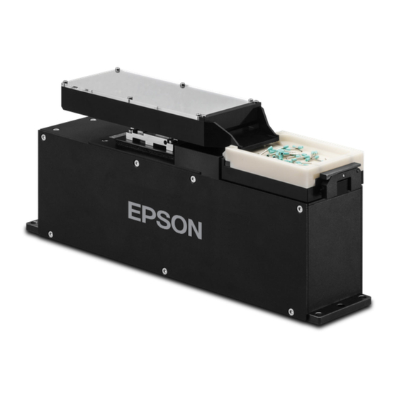
2. Description 2. Description 2.1 First glimpse of product The IF-240 sets new standards in small part feeding. Its 3D vibratory platform allows fast and flexible presentation of small parts (5 × 5 to 15 × 15 mm) to a robot equipped with a vision system. -
Page 16: General Characteristics
2. Description For more information on how to remove or change the platform, refer to 4.2.2. Remove the platform module. For more information on the backlight color and the procedure to exchange the backlight, refer to 4.3.1 Exchanging / installing the backlight. 2.2 General characteristics Do not use the product outside the specifications. -
Page 17: Overall Dimensions
2. Description 2.2.2 Overall dimensions Figure 2-2: Overall dimensions of the IF-240 Characteristic 171 mm Footprint 300 mm D’ 55 mm 150 mm 195 mm Size of vibration platform 132 mm 105 mm Weight with platform and backlight 7.8 kg Additional space is needed around the part feeder to be able to remove the platform module with the integrated tool: Figure 2-3: Overall dimensions with platform “lever”... -
Page 18: Visual Signals
2. Description 2.2.3 Visual signals The LEDs mounted on the unit give important information on the state of the IF-240: Figure 2-4: IF-240 Operating Indicator LEDs State Meaning Blinking Time on: 100ms System in standby Blinking Time on: 900ms System in service 24V on S-Power input (refer to 2.4.2 Power connection for more information) Blinking... -
Page 19: Performance
2. Description 2.3 Performance 2.3.1 Picking surface The maximum picking surface dimensions corresponds to the IF-240 platform size: Figure 2-5: Picking surface 195mm 150mm 2.4 Electrical interfaces 2.4.1 Overview The IF-240 is a standalone module with its own controller. The electrical interfaces of the IF-240 are located on the rear panel of the product: Figure 2-6: Electrical interfaces of the IF-240 A Power connection... -
Page 20: Power Connection
2. Description 2.4.2 Power connection Before supplying power to the part feeder, check that the distribution voltage is the same as the nominal voltage. Never disconnect the power cables when the unit is on. Always turn the machine off and then cut the power. Use PELV (protected extra-low voltage) nominal voltage. - Page 21 2. Description The following connection schematic shows the methods to connect to the IF-240 depending if your application requires an external relay to ensure that the backlight is safely switched off or not. In any case, both “Power” and “S-Power” have to be supplied for using the backlight.
-
Page 22: Communication
2. Description 2.4.3 Communication The communication with the IF-240 is established by a standard Ethernet communication via RJ45 port (A) Figure 2-10: Ethernet connection RJ45 Characteristic Value Default IP address 192.168.0.64 Default subnet mask 255.255.255.0 Port 4001 MAC address Can be read by ARP request For more information on the procedure to restore the default IP address, please refer to 4.3.2 Recover IP address using default IP address. -
Page 23: Digital Output For Hoppers 1 And 2
2. Description 2.4.4 Digital output for hoppers 1 and 2 A standard M8 four-pins male cable enables transmission of the digital output signal to hopper. It must be connected as follows: Figure 2-11: Digital output for hoppers Signal description Hopper 0V GND Digital Output 1 +24VDC... -
Page 24: Mechanical Interfaces
2. Description 2.5 Mechanical interfaces 2.5.1 Mounting the IF-240 To ensure proper behavior of the IF-240, secure fastening to a solid surface is necessary. The holes in the base plate of the IF-240 can be used to attach it with four M6 screws. Repeatable positioning of the IF-240 can be done by using positioning pins (possible on both sides). -
Page 25: Accessories And Optional Modules
2. Description 2.6 Accessories and optional modules 2.6.1 Platform The flat platform can be used for a large variety of components, mainly components with a flat surface allowing a stable resting position. NOTE Part Feeding 7.0 IF-240 Rev.5... - Page 26 2. Description Mechanical interfaces of the platform Part Feeding 7.0 IF-240 Rev.5...
-
Page 27: Backlight
2. Description 2.6.2 Backlight The following backlights are available: Backlight color Wavelength White 6500 K For more information on the backlight color and the procedure to exchange the backlight, please refer to 4.3.1 Exchanging / installing the backlight. For more information on the backlights, contact the supplier NOTE ... - Page 28 2. Description 2.6.3.1 Connection The hopper is delivered with the control unit with cables ready to install. 2.6.3.2 Control unit The vibration intensity of the hopper can be adjusted with the potentiometer. Place the control unit in a position that allows access to the NOTE ...
- Page 29 2. Description 2.6.3.3 Hopper interfaces The hopper is delivered with mounting feet ready to be attached using screws (4× M8× 20) 2 liters version 3 liters version Part Feeding 7.0 IF-240 Rev.5...
-
Page 30: Transportation, Handling, And Installation
3. Transportation, handling, and installation 3. Transportation, handling, and installation 3.1 Packaging of the product, transportation and handling The transportation of the product must be made in accordance with the specific terms indicated on the package (top, bottom, fragile, etc.). In addition, pay particular attention to the following points: - Be aware of the weight and take care when transporting the system. -
Page 31: Unpacking Instructions
Important information is on this sticker; such as the power consumption rating and the type name and serial number that you will need for any kind of correspondence with Epson. 3.4 Installation and storage environment - The IF-240 must be mounted on a smooth, flat and solid surface. -
Page 32: Storage Environment
3. Transportation, handling, and installation 3.4.2 Storage environment The storage environment should be similar to the operating environment. In addition, you should protect the IF-240 against dust Part Feeding 7.0 IF-240 Rev.5... -
Page 33: Maintenance And Component Replacement
4. Maintenance and component replacement 4. Maintenance and component replacement 4.1 Safety precautions 4.1.1 General safety precautions There are no user serviceable parts inside the product. Contact the supplier of your region for maintenance. In cases of non conformity, the product guarantee will expire. WARNING Do not operate the system when it is damaged. -
Page 34: Maintenance
4. Maintenance and component replacement 4.2 Maintenance For any kind of maintenance, always use Epson products. WARNING 4.2.1 Periodic maintenance schedule The IF-240 is virtually maintenance-free. However, simple inspections should be performed at regular intervals to ensure optimum performances, and safe operation of your product. -
Page 35: Remove The Platform Module
4. Maintenance and component replacement 4.2.2 Remove the platform module Be sure that the backlight is off before removing the platform module. DANGER Risk of crushing. Do not place your finger between the platform and the locking mechanism. Figure 4-1: Remove the platform Step 1 Pull out the integrated tool (A) and move it away for freeing the platform (B). -
Page 36: Control And Cleaning Of The Platform
4. Maintenance and component replacement 4.2.3 Control and cleaning of the platform Material needed: - Lint-free cloth - Isopropanol alcohol Figure 4-2: Platform Step 1 Control the surface state of the platform (A) and be particularly careful of the following points: - Dirt or spotted surface - Oily or greasy surface... -
Page 37: Component Replacement
For a list of the components which can be replaced directly by the customer, please contact the supplier of your region. For any other repair, the product must be returned to the manufacturer. For any kind of replacement, always use Epson products. WARNING 4.3.1 Exchanging / installing the backlight Be sure that all power sources and other cables to the unit are disconnected before changing the backlight. - Page 38 4. Maintenance and component replacement Step 3 Unplug the backlight connector (C). Step 4 Remove the old backlight (D). Insert the new backlight (E). Step 5 Align the backlight module flush with the mirror support (F) and tighten the four bolts (G). Use a flat wrench size 5.5.
- Page 39 4. Maintenance and component replacement Step 6 Plug in the backlight connector (H). Step 7 Remount the covers (I) and (I’) on both sides. Part Feeding 7.0 IF-240 Rev.5...
-
Page 40: Recover Ip Address Using Default Ip Address
4. Maintenance and component replacement 4.3.2 Recover IP address using default IP address The following procedure explains how to reboot the IF-240 so that is uses the default IP address, subnet mask and TCP port number to be able to modify the IP address, subnet mask and TCP port number when they are unknown and cannot be found. - Page 41 4. Maintenance and component replacement Step 4 Parameters in memory can now be modified by RC+. For more details, refer to Software 2.1 System Settings. Step 5 When parameters are defined as desired, replace selector 2 in position (C). 1 2 3 4 Step 6 Disconnect and reconnect the power cable (or switch off and switch on the power of the IF-240).
- Page 42 4. Maintenance and component replacement Part Feeding 7.0 IF-240 Rev.5...