Table of Contents
Advertisement
Advertisement
Table of Contents

Related Manuals for Fujitsu TeamPoS 2000


Summary of Contents for Fujitsu TeamPoS 2000
- Page 1 TeamPoS 2000 MAINTENANCE MANUAL...
- Page 2 MAINTENANCE MANUAL TeamPoS 2000 Rev 3.0 90000291...
- Page 3 TeamPoS 2000 MAINTENANCE MANUAL ® TeamPoS 2000 Installation and Maintenance Manual 90000291 Rev 3.0...
- Page 4 MAINTENANCE MANUAL TeamPoS 2000 This page intentionally left blank Rev 3.0 90000291...
- Page 5 The development of Fujitsu products and services is continuous and published information may not be up to date. It is important to check the current position with Fujitsu Transaction Solutions Inc. This document is not part of a contract or license save insofar as may be expressly agreed.
- Page 6 MAINTENANCE MANUAL TeamPoS 2000 Regulatory Information Emissions Radio Frequency Interference Requirements – U.S.A This equipment has been tested and found to comply with the limits for a Class A digital device pursuant to Part 15 of the FCC Rules. These limits are designed to provide reasonable protection against harmful interference when the equipment is operated in a commercial environment.
- Page 7 TeamPoS 2000 MAINTENANCE MANUAL Safety Lithium & Lead Acid Battery Caution: There is a danger of explosion if the lead acid battery is incorrectly replaced. Replace only with the battery listed in Chapter 10. Dispose of the used battery according to manufacturer’s instruction.
-
Page 8: Table Of Contents
TeamPoS 2000 Front Panel Switch and LCD Matrix · · · · · · · · · · · · · · · · · · · · · · · · · · · · · · · · ·... - Page 9 TeamPoS 2000 MAINTENANCE MANUAL 3.7.1 Model D15 LCD Displays (New Release) · · · · · · · · · · · · · · · · · · · · · · · · · · · · · · · · · · · · · · · · · · 3-9 3.7.2...
- Page 10 MAINTENANCE MANUAL TeamPoS 2000 Chapter 4 SITE PREPARATION · · · · · · · · · · · · · · · · · · · · · · · · · · · · · · · · · · · · · · · · · · · · · · · · · · · · · · · · · · · · · 4-1 Unpacking ·...
- Page 11 TeamPoS 2000 MAINTENANCE MANUAL 5.3.7 Retail I/O BoardPorts 3, 4 & 6 Connector Signals· · · · · · · · · · · · · · · · · · · · · · · · · · · · · · · · · · · 5-17 5.3.8...
- Page 12 5.12 Connecting Retail I/O, TeamCOMBO & TeamUSB Board Cables · · · · · · · · · · · · · · · · · · · · · · · · · 5-75 5.12.1 TeamPoS 2000 with Retail I/O Board Connector Layout-A Motherboard · · · · · · · · · · · · · · · · 5-76 TeamPoS 2000 with TeamCOMBO Board Connector Layout-A Motherboard 5.12.2...
- Page 13 TeamPoS 2000 MAINTENANCE MANUAL PC Board Replacement · · · · · · · · · · · · · · · · · · · · · · · · · · · · · · · · · · · · · · · · · · · · · · · · · · · · · · · · · · · · · 7-3 M Motherboard Layout ·...
- Page 14 MAINTENANCE MANUAL TeamPoS 2000 8.1.8 Secondary IDE Master - M Motherboard · · · · · · · · · · · · · · · · · · · · · · · · · · · · · · · · · · · · · · · · · · 8-8 8.1.9...
- Page 15 TeamPoS 2000 MAINTENANCE MANUAL Chapter 9 BIOS SETUP PROCEDURES - A Motherboard · · · · · · · · · · · · · · · · · · · · · · · · · · · · · · · · · · · · · · · · 9-1 Opening CMOS Setup Screen - A Motherboard ·...
- Page 16 MAINTENANCE MANUAL TeamPoS 2000 This page intentionally left blank. Rev 3.0 90000291...
-
Page 17: Chapter 1 Overview
TeamPoS 2000 MAINTENANCE MANUAL Chapter 1 Overview The following sections provide a brief overview of the TeamPoS 2000 control units and peripherals: The TeamPoS 2000 is a state-of-the-art Point-of-Sale (PoS) terminal. It contains standard PC components such as CPU, memory, hard disk, video and audio and can be used as a PC, subject to operating system and licensing restrictions, to run standard PC applications, such as word processing, spreadsheets, etc. -
Page 18: Teampos 2000 Control Unit Flow Diagram
TeamPoS 2000 MAINTENANCE MANUAL TeamPoS 2000 Control Unit Flow Diagram The following graphic shows a high level overview of the TeamPoS 2000 Control Unit. PC Board Operator Panel CPU: Celeron / Pentium III Memory: Up to 768MB CD-ROM/DVD Lithium Battery... -
Page 19: Front Panel Leds And Switches
TeamPoS 2000 MAINTENANCE MANUAL Front Panel LEDs and Switches The following graphic and table show the TeamPoS 2000 unit LEDs and switches. 90000291 Rev 3.0... -
Page 20: Teampos 2000 Front Panel Switch And Lcd Matrix
TeamPoS 2000 MAINTENANCE MANUAL 1.2.1 TeamPoS 2000 Front Panel Switch and LCD Matrix Name Switch/LED Mounting LED Color Remark Position Power SW Outside of — Depending on BIOS setup, the power switch can be Front Door instant off or delayed off. -
Page 21: Intelligent Pins (Product Identification Numbers)
TeamPoS 2000 MAINTENANCE MANUAL Intelligent PINs (Product Identification Numbers) All control units have a number called an Intelligent PIN. This number specifies the configuration as manufactured. The following lists the options. If the actual configuration of the control unit is different than the Intelligent PIN, it was upgraded/changed after being manufactured. - Page 22 TeamPoS 2000 MAINTENANCE MANUAL This page intentionally left blank. Rev 3.0 90000291...
-
Page 23: Chapter 2 - External View And Environmental
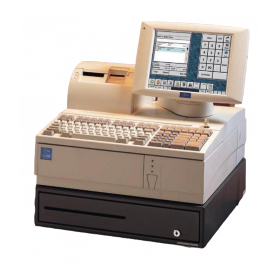
TeamPoS 2000 MAINTENANCE MANUAL Chapter 2 - EXTERNAL VIEW AND ENVIRONMENTAL SPECIFICATIONS EXTERNAL VIEW (Standard Series without cash drawer) Note: This is a typical integrated configuration. Depending on the store environment, the configuration and components may differ. 90000291 Rev 3.0... -
Page 24: Environmental Specifications
TeamPoS 2000 MAINTENANCE MANUAL Environmental Specifications Specifications Unit TP2000 Main Unit 133PQ/UQ 92M/U 104P Key Compact Keyboards Keyboards Compact Standard Keyboard Clearance Space Front 75mm 3" Rear 50mm 2" Right Left Weight 12kg. 1.1kg. 1.2 kg. 1.1 kg. (component only) 26.5 lb. - Page 25 TeamPoS 2000 MAINTENANCE MANUAL Specifications Unit D15 LCD A12/D12 Integrated DT50II Compact Display Customer Cash Printer Display Drawer Display (low-pole) Weight 4.1 kg, 3.3 kg. 1.1 kg. 5.8 kg. 6.4kg. (component only) 9.0 lb. 7.3 lb. 2.5 lb. 12.8 lb.
- Page 26 TeamPoS 2000 MAINTENANCE MANUAL This page intentionally left blank. Rev 3.0 90000291...
-
Page 27: Chapter 3 Dimensions
Dimensions are approximate external and in millimeters (inches). The TeamPoS 2000 control unit is available in two sizes, compact and standard. Both units can be stacked, where peripherals (printer, keyboard, operator display and customer display) are stacked on top of the control unit. This requires brackets to be installed on the control unit that restrain movement of the peripherals. -
Page 28: Compact Teampos 2000 12.1" Lcd Stacked Configuration Dimensions
TeamPoS 2000 MAINTENANCE MANUAL Compact TeamPoS 2000 12.1" LCD Stacked Configuration Dimensions Standard TeamPoS 2000 12.1" LCD Stacked Configuration Dimensions Note: Both standard and compact units above with 12.1" LCD units are shown with long integrated customer display poles. The standard unit with 15" LCD on page 3-1 is shown with a long dispersed customer display pole. -
Page 29: Control Units
TeamPoS 2000 MAINTENANCE MANUAL Control Units Compact TeamPoS 2000 Control Unit (See Intelligent PIN # Section 1.3) Standard TeamPoS 2000 Control Unit (See Intellient PIN Section 1.3) 90000291 Rev 3.0... -
Page 30: Keyboards
TeamPoS 2000 MAINTENANCE MANUAL Keyboards 3.5.1 Model 133UQ Keyboard Dimensions PIN #s 90000626-629 [90000629 shown]) 3.5.2 Model 104P Keyboard Dimensions (Pin #90000175) Rev 3.0 90000291... -
Page 31: Model 133Pq Keyboard Dimensions
TeamPoS 2000 MAINTENANCE MANUAL 3.5.3 Model 133PQ Keyboard Dimensions (PIN #PB600335) 3.5.4 Basic Model 92M and 92U Keyboard Dimensions (PIN # 53876001M 900000630) 90000291 Rev 3.0... -
Page 32: Model 92M & 92U Keyboard With Msr And Display Dimensions
TeamPoS 2000 MAINTENANCE MANUAL 3.5.5 Model 92M & 92U Keyboard with MSR and Display Dimensions (PIN #s 53876004M- 006M 90000630-32) 3.5.6 Model 92M Keyboard with Vertical Key-Lock Dimensions (PIN #s 53876005EM, 007M, 008M, 009M, 010EM, 011EM, 012EM) Rev 3.0 90000291... -
Page 33: Cash Drawers
TeamPoS 2000 MAINTENANCE MANUAL Cash Drawers 3.6.1 Model TP10 Cash Drawer (PIN #s 54258001- 003) 3.6.2 MP5 Cash Drawer, Compact (PIN #s CA82003-5002 & -5003) 90000291 Rev 3.0... -
Page 34: Nf5 Cash Drawer
TeamPoS 2000 MAINTENANCE MANUAL 3.6.3 NF5 Cash Drawer (PIN #s 90000576-577) 3.6.4 Model NAF Cash Drawer (PIN #s 4669001-006) (withdrawn) Rev 3.0 90000291... -
Page 35: Displays
TeamPoS 2000 MAINTENANCE MANUAL Displays 3.7.1 Model D15 LCD Displays (New Release) The D15 LCD is a 15" LCD which supports both analog and digital interfaces in the same unit. To use the D15 as an analog device simply connect using a VGA cable. To... -
Page 36: Lcd Bracket Mounting
TeamPoS 2000 MAINTENANCE MANUAL 3.7.2 LCD Bracket Mounting The D15 LCD uses a standard 100mm (4") vesa mount.. 3.7.3 Single Stacked D15 LCD 3-10 Rev 3.0 90000291... -
Page 37: Single Stacked D15 Lcd W/Customer Display
TeamPoS 2000 MAINTENANCE MANUAL 3.7.4 Single Stacked D15 LCD w/customer display 3.7.5 Single Dispersed D15 LCD (PIN90000820-24, 90000855, 90001127 monitors with 90000823 stand) 90000291 Rev 3.0 3-11... -
Page 38: Single Dispersed Lcd With Msr
TeamPoS 2000 MAINTENANCE MANUAL 3.7.6 Single Dispersed LCD with MSR (PIN #'s 90000820, 90000855, 90001127 monitors, 90000823 stand, 90000831 MSR 90000821monitor (withdrawn)) 3.7.7 Single Dispersed D15 with Keypad and MSR (PIN #'s 90000820, 90000855, 900011127 monitors, 90000823 stand, 90000830 (keypad & MSR w/lock) -
Page 39: Models D12 And A12 Lcd Displays
TeamPoS 2000 MAINTENANCE MANUAL Models D12 and A12 LCD Displays The 12.1" LCDs come in six models, with two technologies and two interfaces. The two technologies are DSTN and TFT and the two interfaces are digital and analog. LCDs may have a touch option. -
Page 40: Lcd Bracket Mounting
MAINTENANCE MANUAL 3.8.1 LCD Bracket Mounting The following information is provided for customers who do not use the optional Fujitsu Transaction Solutions Inc. mounting brackets. An optional VESA compliance adapter is also available for mounting in situations that require VESA mounting. The VESA adapter is attached to the LCD using the 4 mounting screws. -
Page 41: Single Stacked Lcd
TeamPoS 2000 MAINTENANCE MANUAL 3.8.2 Single Stacked LCD (all single 12.1" stacked LCDs fit with stand, PIN # 90000162) 3.8.3 Single Dispersed LCD with dispersed stand (all single dispersed 12.1" LCDs fit with optional stand, PIN # 90000552) 90000291 Rev 3.0... -
Page 42: Single Dispersed Lcd - Alternate Mount
TeamPoS 2000 MAINTENANCE MANUAL 3.8.4 Single Dispersed LCD – Alternate Mount (alternate dispersed LCD stand fits all single 12.1" LCDs, PIN # 90000171, withdrawn) 3.8.5 TeamKey (all 12.1" LCDs fit keypad, PIN #90000354 & dispersed stand, PIN # 90000452) 3-16 Rev 3.0... -
Page 43: Lcd With Msr (Dispersed)
(all 12.1" LCDs with stacked stand, PIN # 90000366) Note: This dual display stand can only be stacked. When the display is stacked it extends 2" beyond the TeamPoS 2000 and 3" beyond the cash drawer at the back of the unit. -
Page 44: Other Options
TeamPoS 2000 MAINTENANCE MANUAL 3.8.8 Other Options G Vision (PIN #s L5EX-TA) 3.8.9 CRTs, 9” (Active PIN #s 58312001, PB000009 Withdrawn PIN #s PB600440 & 441) 3-18 Rev 3.0 90000291... -
Page 45: Crt, 14
When the 14" CRT Monitor is used in a stacked configuration, a stacking tray is mounted on the control unit to provide support for the monitor and other peripherals (see photo below). TeamPoS 2000 (Standard only) with Peripherals Including 14” CRT on Stacking Tray ( PB600307... -
Page 46: Vf50 & Vf50U Customer Displays (Dispersed Configuration)
TeamPoS 2000 MAINTENANCE MANUAL 3.8.11 VF50 & VF50U Customer Displays (dispersed configuration) (VF50 Display, PIN # CA05951-2921; VF50U Display, PIN #KD02902-0171 short pole (0.3 meter) kit, PIN # PB501002; tall pole (0.6 meter) kit), PIN # PB501003 3-20 Rev 3.0... -
Page 47: Printers
TeamPoS 2000 MAINTENANCE MANUAL Printers 3.9.1 Model DT50/DT50II Printer (PIN #s 90000048, 90000056-057, 90000541-542 90000772-773) 3.9.2 Model DT50II TranScan Printer (PIN90000838) 90000291 Rev 3.0 3-21... -
Page 48: Model Tm-T88Iii Printer
TeamPoS 2000 MAINTENANCE MANUAL 3.9.3 Model TM-T88III Printer (PIN #90000658) 3.9.4 Model TM-T90 Printer (90000492) 3-22 Rev 3.0 90000291... -
Page 49: Model A758 & A760 Printers
TeamPoS 2000 MAINTENANCE MANUAL 3.9.5 Model A758 & A760 Printers Dimensions for the A758 and A760 printers are the same. (A760 - PIN #s 90000697 & 90000755) (A758 - PIN #s PB600553-556) 3.9.6 Model A794 Printer (PIN # PB600557, withdrawn) 90000291 Rev 3.0... - Page 50 TeamPoS 2000 MAINTENANCE MANUAL This page intentionally left blank. 3-24 Rev 3.0 90000291...
-
Page 51: Chapter 4 Site Preparation
• Inspect the exterior of each unit for any obvious physical damage (scratches or abrasion on painted or display surfaces, or on plastic surfaces) that could have occurred during shipping. • Damaged equipment received from a source other than Fujitsu Transaction Solutions Inc.'s Foothill Ranch facility should be reported to the sender. 90000291... -
Page 52: Reporting Shipment Damage
If any damage is detected, it is both the recipient's and the carrier's responsibility to note the damage. Follow all applicable policies and procedures for notifying the carrier, management, and Fujitsu, for reporting the damage, and for filing damage claims. Please note that all components are packaged separately. Keep the packaging in case it is necessary to return any of the components. -
Page 53: Determining Power Requirements
(for example, vacuum cleaners) into the same power circuit as the terminal. General Requirements The TeamPoS 2000 power supply is autoranging and can be connected to nominal 115VAC or 230VAC power without any adjustments. The following are general electrical supply requirements: •... -
Page 54: Installation With Other Equipment
TeamPoS 2000 MAINTENANCE MANUAL Installation with Other Equipment In most cases, dedicated AC mains circuits are not required for the TeamPoS Series terminals. In rare instances, other electrical equipment sharing power with the terminal may cause adverse effects on the terminal. When this occurs, electrical isolation may be required and is the responsibility of the customer or installing contractor. -
Page 55: Mains Power Cable
4.10 Mains Power Cable Fujitsu supplied cables must be used to connect the system to the power supply outlet. The mains power cables for the TeamPoS Series terminals are terminated with a plug suitable for the ordering country. The following is a list of available power cables: •... - Page 56 TeamPoS 2000 MAINTENANCE MANUAL This page intentionally left blank. Rev 3.0 90000291...
-
Page 57: Chapter 5 Installation
5.1. Cover Removal/Installation Process In many cases, TeamPoS 2000 control units will be fully configured from the factory or at configuration centers. Others will be configured during installation. This section shows how to access the control unit components to add or change configurations. Accessing the TeamPoS 2000 internal components always requires the removal of the front panel. -
Page 58: Side Cover (Left)
TeamPoS 2000 MAINTENANCE MANUAL Manually loosen the two metal thumbscrews on the right and left to remove the entire front cover. A coin or screwdriver can be used to loosen the thumbscrews if they are too tight. 5.1.2 Side Cover (Left) Caution: Be sure to observe all ESD precautions and power OFF procedures. -
Page 59: Rear Cover
TeamPoS 2000 MAINTENANCE MANUAL To mount the side cover again, first insert the tab at the lower back of the cover into the hole in the cabinet, insert the remaining tabs, and then slide cover to the rear. 5.1.3 Rear Cover While facing the back of the device, push the buttons on the right and left side to remove the rear cover. -
Page 60: Top Cover
TeamPoS 2000 MAINTENANCE MANUAL Caution: Be sure to observe all ESD precautions and power OFF procedures. 5.1.4 Top Cover Lift the keyboard, and then disconnect the cable from the bottom to remove the keyboard. Remove the rear cover (see section 5.1.3). - Page 61 TeamPoS 2000 MAINTENANCE MANUAL 4. Slide the pedestal with the LCD and the Customer Display (if installed) slightly toward the front, then lift and remove the pedestal. 5. Remove the printer in the same manner. 6. Remove front cover (see section 5.1.1) 90000291 Rev 3.0...
- Page 62 TeamPoS 2000 MAINTENANCE MANUAL 7. Slightly pull the top cover toward the front (in the direction indicated by the arrow), then lift and remove the cover. To mount the top cover again, reverse the removal procedure. Note: There is a locking tab on the inside of the top cover. Ensure that the tab on the back of the top cover goes under the chassis prior to pushing it into place.
-
Page 63: Installing D12 And A12 Lcd Brackets
TeamPoS 2000 MAINTENANCE MANUAL 5.1.5 Installing D12 and A12 LCD Brackets 5.1.5.1 Installing keyboard, printer, CRT and LCD brackets For stacked configurations, keyboard, printer and operator display brackets are available. The brackets attach to the top of the control unit and restrain the peripherals from sliding. - Page 64 TeamPoS 2000 MAINTENANCE MANUAL hole on the top cover where a bracket will not be used. For dispersed configurations, all holes are covered. 5.1.5.2 D12 and A12 Stacking Bracket Locations The following shows peripheral bracket locations on the compact and standard control units.
- Page 65 TeamPoS 2000 MAINTENANCE MANUAL shown) is also available that makes the connector cover flush with the peripherals. The standard connector cover protrudes slightly beyond the peripherals if an LCD and model DT50/DT50II printer are selected. Attach filler bracket to top cover of unit with bracket hooks facing inward.
-
Page 66: Pci Add-In Card(S)
TeamPoS 2000 MAINTENANCE MANUAL Caution: Be sure to observe all ESD precautions and power OFF procedures 5.1.6 PCI Add-In Card(s) Remove the front cover (See section 5.1.1). Remove the side cover (left) (See section 5.1.2). Remove top cover (See section 5.1.4). -
Page 67: Adding Main Memory
TeamPoS 2000 MAINTENANCE MANUAL Adding Main Memory 5.2.1 Memory Configuration Note: Up to two PCI add-in cards can be installed. 5.2.1.1 Pentium III Motherboard Any combination of 64, 128, and 256MB DIMMs can be installed in any of the three sockets on the motherboard, allowing from 64MB to 768MB memory. -
Page 68: Accessing And Configuring
TeamPoS 2000 MAINTENANCE MANUAL 5.3 Accessing and Configuring (PIN # 90000161) 5.3.1 Retail I/O Board Pin layout To access jumpers: Remove front cover (see section 5.1.1). Remove side cover (left) (see section 5.1.2). Retail I/O Board Layout 5-12 Rev 3.0... -
Page 69: Retail I/O Board Settings
TeamPoS 2000 MAINTENANCE MANUAL 5.3.2 Retail I/O Board Settings Switch Definition Settings (Default in Bold) Port 1/2 DC Powered or Standard COM-I/F for Port 1/2 PORT 1 STD COM DC Powered PORT 2 STD COM DC Powered * Two jumpers required for each setting. -
Page 70: Printer Jumpers
TeamPoS 2000 MAINTENANCE MANUAL Switch Definition Settings (Default in Bold) COM3 IRQ IRQ3 IRQ10 OFF Only one IRQ switch can be ON IRQ4 ON IRQ11 OFF Note: Only applies when SW 3, position 4 is IRQ9 IRQ12 OFF set for COM 3/4... -
Page 71: Ptr (Printer) Connector Signals
TeamPoS 2000 MAINTENANCE MANUAL 5.3.4 PTR (Printer) Connector Signals Connector type: Female D15, (See section 5.3.1 for locations.) Note: Pin outs may differ depending on jumper placement, see section 5.3.3. Pin # Signal Signal FD20 Mode ESC/PoS Mode (Fujitsu printer signals) -
Page 72: Retail I/O Board. Ports 1 And 2 Connector Signals
TeamPoS 2000 MAINTENANCE MANUAL 5.3.5 Retail I/O Board. Ports 1 and 2 Connector Signals Connector type: Male D9, (RS-232 ports) (See section 5.3.1 for locations.) Pin # Signal when Signal when DC Powered Mode Standard Com Mode 5.3.6 Retail I/O Board.Port 5 Connector Signals... -
Page 73: Retail I/O Boardports 3, 4 & 6 Connector Signals
TeamPoS 2000 MAINTENANCE MANUAL 5.3.7 Retail I/O BoardPorts 3, 4 & 6 Connector Signals Connector type: Female D9 Pin # Signal +24V 5.3.8 DRW Connector Signals (Cash drawer port) Connector type: Female D9 Pin # Signal +24V RET CD1 Status... -
Page 74: Installing The Teamcombo Board
TeamPoS 2000 MAINTENANCE MANUAL Installing the TeamCOMBO Board (PIN #90000273) 5.4.1 TeamCOMBO Board Pin Layout To access jumpers: Remove front cover (see section 5.1.1). Remove side cover (left) (see section 5.1.2). 5-18 Rev 3.0 90000291... -
Page 75: Team Combo Board Settings
TeamPoS 2000 MAINTENANCE MANUAL 5.4.2 Team COMBO Board Settings Switch Definition Settings (Default in Bold) Port 1/2 DC Powered or Standard COM-I/F for PORT 1 STD COM DC Powered Port 1/2 PORT 2 STD COM DC Powered * Two jumpers requird for each setting. -
Page 76: Teamcombo Board. Ports 1 And 2 Connector Signals
TeamPoS 2000 MAINTENANCE MANUAL The following tables contain the connector signals for the ports on the TeamCOMBO Board. A diagram of each connector and its pin out locations is shown after each table. 5.4.3 TeamCOMBO Board. Ports 1 and 2 Connector Signals Note: Pin outs may differ depending on jumper placement, see section 5.4.2. -
Page 77: Teamcombo Board. Ports 3 And 4 Connector Signals
TeamPoS 2000 MAINTENANCE MANUAL 5.4.4 TeamCOMBO Board. Ports 3 and 4 Connector Signals Connector type: Female D9 Pin # Signal +24V 5.4.5 DRW Connector Signals Connector type: Female D9 (Cash drawer port) Pin # Signal +24V RET CD1 Status CD1 SOL+... -
Page 78: Teamcombo Board. Usb Connectors - 4 Ports
TeamPoS 2000 MAINTENANCE MANUAL 5.4.6 TeamCOMBO Board. USB Connectors – 4 Ports Powered Retail USB connector (24 VDC or 12 VDC) Pin # DC-Out Mode 5 VDC USB Power Data - Std. USB Signals Data + Ground 24 VDC Return, USB ports 1,2, and 3... -
Page 79: Teamusb Settings
TeamPoS 2000 MAINTENANCE MANUAL TeamUSB Settings Switch Definition Settings (Default in Bold) BATL Detect Lead Acid Battery Alarm Disable Enable FAN1 Detect CPU Fan Alarm Disable Enable FAN2 Detect PSU Fan Alarm Enable Disable FAN3 Detect Chassis Fan Alarm Enable... -
Page 80: Teamusb Board. Usb Connectors - 7 Ports
TeamPoS 2000 MAINTENANCE MANUAL 5.5.1 TeamUSB Board. USB Connectors - 7 Ports The TeamUSB board can only be used with the new riser card (Pin #KD20033-B41X). When using the TeamUSB with the Pentium III motherboard, one of the USB ports on the motherboard is used to connect the I/O board and a label covers one of the USB connectors. -
Page 81: Teamusb Board Drw Connector Signals
TeamPoS 2000 MAINTENANCE MANUAL 5.5.2 TeamUSB Board DRW Connector Signals Connector type: Female D9 (Cash drawer port) Pin # Signal +24V Return CD0-Open CD0-Sol CD1-Sol CD1-Open +24V Return 5.5.3 TeamUSB Board, Powered USB Connectors - 7 ports Pin # USB +24V USB +12V Ports 1, 2, 3 &... -
Page 82: Riser Card Connectors
TeamPoS 2000 MAINTENANCE MANUAL Riser Card Connectors Note: Dashed lines are components on the opposite side. There are two riser cards: Revised riser card, 2 PCI slots, KD20033-B41X supports TeamUSB, TeamCOMBO and Retail I/O boards. Original riser card, 2 PCI slots, CA21259-B21X supports Retail I/O and TeamCOMBO only. -
Page 83: Cd-Rom/Cd-Rw/Dvd (Media Player) Installation
TeamPoS 2000 MAINTENANCE MANUAL CD-ROM/CD-RW/DVD (Media Player) Installation The term media player in this manual refers to any of the options: CD-ROM, CD-RW or DVD. The following instructions show how to install a media player upgrade, where none was previously installed. If the media player is being replaced, due to failure, refer to the maintenance section of this manual. - Page 84 TeamPoS 2000 MAINTENANCE MANUAL Insert the media player through the front opening with the ribbon cable and audio cable. See photo on opposite page. Ensure guides on left hand side of media player align above chassis guides. Route the audio cable under the floppy disk ribbon cable, which is attached to the riser card, and connect to the audio connector on the riser card.
-
Page 85: Pos Peripheral Installation
WinProgrammer 2.0; or link through Fujitsu's FTP site at ftp://ftp.ftxs.fujitsu.com/pos. possustaining, Retail Keyboard 133UQ PrehDrivers shortcut. The firmware update utility is also in this same location on Fujitsu's FTP site. Look for 'Bootloader.' 90000291 Rev 3.0 5-29... -
Page 86: Model 92U Keyboard Unit (Programmable)
(PIN #s 90000630 keyboard, 90000631 MSR, 90000632 display, ) This keyboard is scheduled for release late Q2 of 2004. When it is released, drivers and the keyboard programming utility will be available through Fujitsu's FTP site at ftp://ftp.ftxs.fujitsu.com/pos, choose possustaining... -
Page 87: Model 133Pq Keyboard Unit (Not Programmable)
TeamPoS 2000 MAINTENANCE MANUAL 5.8.2.1 Model 92U Keyboard Switch Settings The keyboard assembly has a 10-position rotary address switch located next to the interface cable connection. See photo above. Switch Number Function Offline Diagnostics MSR 1, 2 &3 Not used... - Page 88 TeamPoS 2000 MAINTENANCE MANUAL 5.8.3.1 Model 133PQ Keyboard Switch Settings The 133PQ switches are located in the MSR compartment which is entered from the bottom of the keyboard. These settings set the MSR to read track 1 & 2 or track 2 & 3.
-
Page 89: Model 104P Keyboard Unit (Compact Keyboard)
TeamPoS 2000 MAINTENANCE MANUAL Fit the MSR into the frame inside the MSR cover. The circuit board should face the latch. This is the only way that the MSR can be installed. Be sure the connecting wires come out from under the MSR on the circuit board side. - Page 90 MAINTENANCE MANUAL 5.8.4.1 Model 104P Keyboard Default Layout The following is the default keyboard layout which may not match the customer’s layout. The keyboard is programmable. The keyboard mapping utility is on the Fujitsu FTP site at ftp://ftp.ftxs.fujitsu.com/pos/. 5.8.4.2 Model 104P Keyboard Switch Settings (Compact Keyboard) The Model 104P keyboard has DIP switches as follows.
- Page 91 TeamPoS 2000 MAINTENANCE MANUAL Switch Meaning POS command invalid MSR default Enabled POS command valid (Default) MSR default Disabled KEYMAP A (Default) KEYMAP B (Not Used) KEYMAP C (Not Used) KEYMAP D (NotUsed) 5.8.4.3 Model 104 Keyboard Volume Adjustment The volume control of the buzzer is on the bottom of the keyboard unit. Turning the control clockwise increases the volume.
- Page 92 TeamPoS 2000 MAINTENANCE MANUAL Connect the MSR cable to the MSR unit with the conductors on the cable exposed away from the MSR unit (up). Connect the MSR cable to the MSR unit with the conductors on the cable exposed away from the MSR unit (up).
-
Page 93: Model D15 Lcd Stands
MAINTENANCE MANUAL Model D15 LCD Stands The 15" Liquid Crystal Display (LCD) used with the TeamPoS 2000 is a TFT technology and has both digital and analog interfaces and speakers. Options include touch, keypad and MSR. Touch options are factory installed and cannot be field installed. - Page 94 (A or M) and to the audio port on the bottom of the D15 stand. In dual screen configurations, only one LCD can have the sound enabled. TeamPoS 2000 & D15 Audio Connection for TeamUSB, TeamCOMBO & Retail I/O Boards 5-38 Rev 3.0...
-
Page 95: D15 Lcd Video Data Cable Connections
When two LCDs are supported by one TP2K, one of the monitors must use the DVI connector and the other must use the VGA connector. TeamPoS 2000 & D15 Video Connections for TeamUSB, TeamCOMBO & Retail I/O Boards 90000291 Rev 3.0... -
Page 96: D15 Lcd Dual Monitor Video Cable Connections
VGA cable is connected to the second stand. The DVI cable could just as easily be connected to the second monitor and the VGA cable connected to the first. TeamPoS 2000 & D15 Dual Screen Connections for TeamCOMBO & TeamUSB* Boards * TeamUSB only supported with new riser cad, PIN #KD20033-B41X. -
Page 97: D15 Lcd Power And Data (Touch, Msr And Keypad) Cable Connections
A typical configuration is for non-touch. TeamPoS 2000 Non-touch Connections The powered USB cable makes it possible to connect power and data with the same cable. TeamPoS 2000 w/TeamUSB I/O Board w/Touch and/or MSR and/or Keypad Alternate configuration for non-touch 90000291 Rev 3.0... - Page 98 USB ports and the other end is plugged into any open USB port on the I/O board or one of the standard USB ports on the motherboard. TeamPoS 2000 & Retail I/O Board Touch and/or MSR and/or Keypad 5-42 Rev 3.0...
- Page 99 When using dual screens and the TeamUSB (90000803) or TeamCOMBO II (9001036) I/O boards, only one D15 LCD may be powered by the TeamPoS 2000 using the powered USB connector. The second screen is powered using a power brick. The data for the screen which uses the power brick requires a standard A to A USB connector.
- Page 100 The stacked and dispersed stands contain circuit boards and are wired so that data or power from the TeamPoS 2000 travels within the stand through a specially designed cable. Although there are multiple connectors on the bottom of the stands, there is only one connection to the D15 LCD.
-
Page 101: D15 Cable Summary
TeamPoS 2000 MAINTENANCE MANUAL 5.9.6 D15 Cable Summary Audio Cables, 1 required for each speaker option: LCD Powered USB Cables, 1 required for each LCD in TEAMUSB or TeamCOMBO configuration: CA05951-3131 CBL, D12 Audio/Stacked/0.65M CA05951-3132 CBL, D12 Audio/Dispersed/2.0M 90000835 CBL D15 PWR/USB/STACKED/0.65M CA05951-3133 CBL, D12 Audio/Dispersed/5.0M... -
Page 102: Model D15 Lcd Installation
TeamPoS 2000 MAINTENANCE MANUAL 5.9.7 Model D15 LCD Installation 5.9.7.1 Dispersed Stand Installation Leave the protective sheet attached to the LCD until installation is complete. To install the D15 LCD on either the dispersed stand or the stacked stand (in development): Place the LCD face down on a clean surface. - Page 103 TeamPoS 2000 MAINTENANCE MANUAL Pry off the back panel of the stand to expose access holes. Use a screw driver, inserted through the connector access holes, to assist and to gently tighten the connector turn screws. Tighten the turn screws until the cable connection is secure. Do not overtighten so that it will be possible to remove the LCD if needed.
- Page 104 LCD if needed. Replace protective cover. Install the D15 stacking plate onto the top of the TeamPoS 2000 using thirteen M3 x 5 Phillips Flat Head screws. Install the D15 base mounting bracket using four M3 x 5 Phillips Flat Head screws with the bracket hooks forward.
- Page 105 TeamPoS 2000 MAINTENANCE MANUAL 5.9.7.3 SmartPoSMSR Installation An MSR can be installed on any of the model D15 LCDs. Place the D15 face down on a clean surface, making sure there is nothing that will damage the screen. The bottom edge of the unit should be nearest to you.
- Page 106 TeamPoS 2000 MAINTENANCE MANUAL Thread the connecting wire of the MSR through the shim up to the black insulation. Connect the small white connector to the side of the LCD. The connector has a key so it will only fit one way.
- Page 107 TeamPoS 2000 MAINTENANCE MANUAL Turn the D15 faceup on the counter and using a flat head screw driver, gently pry off the right side frame of the D15. Insert the the small white connector into the port on the D15.
- Page 108 TeamPoS 2000 MAINTENANCE MANUAL Install the D15 base mounting bracket using 4 M3x5 Phillips Flat Head screws. Thread the VF50 cable through the display pole and install the short display pole using three M5 screws. Do not tighten screws completely.
- Page 109 TeamPoS 2000 MAINTENANCE MANUAL Connect all of the required cables to support the D15 display and route the keyboard cable under the stand as shown. Install the D15 display assembly onto the TP2K and route the cables into the rear of the TP2K as shown.
-
Page 110: Models D12 And A12 Lcd Installation
TeamPoS 2000 MAINTENANCE MANUAL 5.10 Models D12 and A12 LCD Installation The 12.1" Liquid Crystal Display (LCD) used with theTeamPoS 2000 is a TFT and has two types of interfaces, digital and analog. Options include touch, speakers, keypad with MSR and MSR only. Touch options are factory installed and cannot be field installed. -
Page 111: Lcd Cable Requirements
TeamPoS 2000 with Digital LCD, Touch & Speaker Options The application software will determine where the touch panels connect to the TeamPoS 2000. The touch cables can be connected to one of the PC board's COM ports or any male 5VDC connector on the Retail I/O Board (Ports 1, 2 or 5) or... - Page 112 TeamPoS 2000 with Digital LCD and Speaker Option The application software will determine where the touch panels connect to the TeamPoS 2000. The touch cables can be connected to one of the PC board's COM ports or any male 5VDC connector on the Retail I/O Board (Ports 1, 2 or 5) or...
- Page 113 TeamPoS 2000with Analog LCD and Touch Option The application software will determine where the touch panels connect to the TeamPoS 2000. The touch cables can be connected to ne of the PC board's COM ports or any male 5VDC connector on the Retail I/O Board (Ports 1, 2 or 5)
- Page 114 Analog LCD and Touch Option only **** The application software will determine where the touch panels connect to the TeamPoS 2000. The touch cables can be connected to one of the PC board's COM ports or any male 5VDC connector on the Retail I/O Board (Ports 1, 2 or 5) or...
- Page 115 LCD Cables (identical connectors at both ends of cable) The application sosftware will determine where the touch panels connect to the TeamPoS 2000. The touch cables can be connected to one of the PC board's COM ports or any male 5VDC connector on the Retail I/O Board (Ports 1, 2 or 5) or TeamCOMBO Board (Port 1 or 2).
-
Page 116: A12/D12 Cable Summary
• The application software will determine where the touch panels connect to the TeamPoS 2000. The touch cables can be connected to one of the PC board's COM ports or any male 5VDC connector on the Retail I/O Board (Ports 1, 2 or 5) or TeamCOMBO Board (Port 1 or 2). -
Page 117: D12/A12 Lcd Stand And Rotating Arm Assembly
TeamPoS 2000 MAINTENANCE MANUAL 5.10.4. D12/A12 LCD Stand and Rotating Arm Assembly Installing LCD Cables Rotate arm completely to one side in order to feed the cables into the stand. This picture shows the metal bracket repositioned to allow for easier routing. To do this a screws is removed from one side only. - Page 118 TeamPoS 2000 MAINTENANCE MANUAL Installing LCD Note: LCD monitors come with a protective film over the screen. Do not remove this film until installation is complete to avoid accidental damage to the surface. 1. Remove filler plate from the back of LCD.
-
Page 119: Model Vf50 & Vf50U Integrated Customer Display With D12/A12 Lcd
TeamPoS 2000 MAINTENANCE MANUAL 5.10.5 Model VF50 & VF50U Integrated Customer Display with D12/A12 LCD Installing the Customer Display Remove two screws from the bottom of the stand and slide off back end of LCD stand. Retain screws. Discard the back of the LCD stand. - Page 120 TeamPoS 2000 MAINTENANCE MANUAL If the integrated pole is long, it will come with two metal brackets. Install the metal brackets as shown and then secure metal brackets and integrated stand with two screws removed in Step 1. Please note there is a left and right bracket.
- Page 121 TeamPoS 2000 MAINTENANCE MANUAL Route the cable as shown. Putting the heat shrink section in the connector opening will make it easier to install the display connector cover. Install connector cover by inserting the right side tab (as viewed from the back of the display) into the display and then pushing down on the left side.
-
Page 122: D12/A12 Lcd With Teamkey Assembly
TeamPoS 2000 MAINTENANCE MANUAL 12. After the entire display unit is completed, set the unit on the TeamPoS 2000 control unit, and slide it back onto the LCD brackets. 5.10.6 D12/A12 LCD with TeamKey Assembly 1. Install cables on the LCD (See LCD Cable Requirements, section 5.8.2.2). - Page 123 TeamPoS 2000 MAINTENANCE MANUAL Install mounting bracket to back of LCD using the 4 screws provided. Two of the screws are longer than the other two. These are to be used on the thicker side (where the metal plate folds back on itself). In the picture below this is the right side.
- Page 124 TeamPoS 2000 MAINTENANCE MANUAL Slide back panel into place (2 taps) and secure with 1 screw. Install LCD assembly on the stand, using four screws. Install rotation mechanism cover (flat side on top) and secure with 2 screws. 5-68 Rev 3.0...
- Page 125 11. Route cables through the check-stand/counter as required. 12. Connect cables to the TeamPoS 2000 control unit. Install LCD with stand in the check-stand/counter. 14. When all peripherals are installed start control unit, (see General Operations, Chapter 6).
-
Page 126: Models D12 And A12 Lcd, 12.1" Adjustments
TeamPoS 2000 MAINTENANCE MANUAL 5.10.7 Models D12 and A12 LCD, 12.1” Adjustments The following graphics show LCD adjustments for all models. Adjust the following, where appropriate: 1. Adjust the brightness. 2. Adjust the sound volume to the maximum (digital versions only). -
Page 127: Model Vf50 And Vf50U Customer Display Settings
TeamPoS 2000 MAINTENANCE MANUAL 5.10.8 Model VF50 and VF50U Customer Display Settings 5.10.8.1 Customer Display Settings Customer display default settings for both the VF50 and VF50U conform to the international font table. See the following table to change to ESC/PoS mode: 5.10.8.2 VF50U Switch Definition... - Page 128 TeamPoS 2000 MAINTENANCE MANUAL Japanese font table (in FJ mode) Standard font table Comm 8 Comm 7 Esc Mode FJ Mode Display on Power Up No Display on Power Up 'Program Loading...Please Wait Note: All switches in the "on" position initiates test mode when VF50U is first powered up.
- Page 129 TeamPoS 2000 MAINTENANCE MANUAL 5.10.8.3 VF50 Switch Definition VF50 Default Switch Settings Japanese font table (in FJ mode) Standard font table Self-test mode Normal Mode 3: OFF 4: OFF FJ mode - Default 3: ON 4: OFF ESC mode 3: OFF...
-
Page 130: Cash Drawers
TeamPoS 2000 MAINTENANCE MANUAL 5.11 Cash Drawers Cash Drawers can be either stacked or dispersed. This section shows the stacked configuration and explains how to set up the unit. When a stacked configuration is shipped it is set up as follows: 1. -
Page 131: Connecting Retail I/O, Teamcombo & Teamusb Board Cables
Colored labels correspond to PC ports and numbered labels correspond to PoS peripheral ports. TeamPoS 2000 with Retail I/O Board Connector Layout with A Motherboard 90000291 Rev 3.0... -
Page 132: Teampos 2000 With Retail I/O Board Connector Layout-A Motherboard
TeamPoS 2000 MAINTENANCE MANUAL 5.12.1 TeamPoS 2000 with Retail I/O Board Connector Layout-A Motherboard Name Defnition PoS Peripheral Port #1 PoS Peripheral Port #2 PoS Peripheral Port #3 PoS Peripheral Port #4 Ports PoS Peripheral Port #5 PoS Peripheral Port #6... -
Page 133: Teampos 2000 With Teamcombo Board Connector Layout-A Motherboard
TeamPoS 2000 MAINTENANCE MANUAL TeamPoS 2000 with TeamCOMBO Board Connector Layout with A Motherboard Note: When the TeamCOMBO board is installed, one of the USB ports on the motherboard becomes unavailable because it is used as a hub for the TeamCOMBO board. - Page 134 TeamPoS 2000 MAINTENANCE MANUAL 5.12.2 TeamPoS 2000 with TeamCOMBO Board Connector Layout-A Motherboard Name Definition PoS Peripheral Port #1 PoS Peripheral Port #2 PoS Peripheral Port #3 PoS Peripheral Port #4 USB1 USB, 24VDC Ports USB2 USB, 24VDC USB3 USB, 24VDC...
-
Page 135: Teampos 2000 With Teamusb Board Connector Layout
TeamPoS 2000 MAINTENANCE MANUAL TeamPoS 2000 with TeamUSB Board Connector Layout with A Motherboard When the TeamUSB board is installed, the top USB port becomes unavailable because it is used as a hub for the new I-O board. A blanking label covers the port used. -
Page 136: Teampos 2000 M With Teamusb Board Connector Layout
TeamPoS 2000 MAINTENANCE MANUAL TeamPoS 2000 with TeamUSB Board Connector Layout with M Motherboard 5.12.4 TeamPoS 2000 M with TeamUSB Board Connector Layout with M Motherboard Name Defnition USB1 USB, 24VDC USB2 USB, 24VDC USB3 USB, 24VDC USB4 USB, 24VDC... -
Page 137: Chapter 6 General Operations
TeamPoS 2000 MAINTENANCE MANUAL Chapter 6 GENERAL OPERATIONS Note: The procedures in this chapter are intended for store personnel. The procedures in succeeding chapters are for authorized service personnel only. System Operations This section contains general and periodic care and maintenance, and power ON and OFF procedures for the TeamPoS terminals. -
Page 138: Power On And Off Sequence
TeamPoS 2000 MAINTENANCE MANUAL Keep the rear cover of the TeamPoS 2000 terminal installed at all times unless the terminal is being serviced. The cover protects the cable connections and ensures adequate clearance for proper ventilation. Make sure all cable connectors are securely installed on the terminal and peripherals to prevent the cables from being accidentally pulled off. -
Page 139: Powering Off
TeamPoS 2000 MAINTENANCE MANUAL Any hardware errors detected on power up will appear on the operator display (CRT or LCD). Note that the Model VF50 two-line alphanumeric display does not display error messages. Note: Some peripherals, such as scanners and scales, may be separately powered. - Page 140 TeamPoS 2000 MAINTENANCE MANUAL This page intentionally left blank. Rev 3.0 90000291...
-
Page 141: Chapter 7 Maintenance
Power ON and OFF Sequence This section presents the general procedures for powering ON and powering OFF the TeamPoS 2000 control unit. The instructions in this section assume that the terminal, operating system, and the application software have been installed. For any additional power-up procedures dictated by the retail application, refer to the manuals provided with the application software. -
Page 142: Powering On
TeamPoS 2000 MAINTENANCE MANUAL 7.1.1 Powering ON Make sure all peripherals are securely connected to the control unit. Make sure the power cord is plugged into the power source. Lift the plastic switch cover at the front of the control unit. -
Page 143: Powering Off
TeamPoS 2000 MAINTENANCE MANUAL Caution: Be sure to observe all ESD precautions and power OFF procedures. When replacing the PC board, ensure AC power cord is removed/unplugged before any maintenance is performed! The power unit of this equipment always supplies electric power to maintain the equipment in standby condition. - Page 144 TeamPoS 2000 MAINTENANCE MANUAL Remove the PC board. Insert the replacement PC board with the plastic rails (underside the motherboard), into the rail guides on the chassis. Insert the PC board with the lever at 90° to chassis, until it meets the mating connector (nearly fully inserted).
-
Page 145: M Motherboard Layout
TeamPoS 2000 MAINTENANCE MANUAL M Motherboard Layout 90000291 Rev 3.0... -
Page 146: M Motherboard Settings
TeamPoS 2000 MAINTENANCE MANUAL 7.3.1 M Motherboard Settings Meaning Default Name Settings KB/MS Power Select 1-2 +5V 2-3 +5V SBY Power COM Port Setting 1-2 RI 3-4 Powered COM (+12V) 5-6 RI 7-8 Powered COM (+12V) PC Beep Jumper Setting... - Page 147 TeamPoS 2000 MAINTENANCE MANUAL Meaning Default Name Settings JP14 DVOB 12C Bus Setting 1-2 M12CDATA 2-3 DDCPDATA JP15 12CCLK 1-2 M12CCLK 2-3 DDCCLK DVI 12C Bus Setting JP16 1-2 MDVIDATA 2-3 MDDCDATA JP17 DVI 12C Bus Setting 1-2 MDVICLK 3-4 MDDCCLK 90000291 Rev 3.0...
-
Page 148: Picture Of M Motherboard
TeamPoS 2000 MAINTENANCE MANUAL 7.3.2 Picture of M Motherboard Rev 3.0 90000291... -
Page 149: A Motherboard Layout
TeamPoS 2000 MAINTENANCE MANUAL 7.3.3 A Motherboard Layout The following figure shows jumper positions. Explanations are provided on the following pages. When setting and exchanging the main board, be sure settings are as follows (default settings), before operation. 90000291 Rev 3.0... -
Page 150: A Motherboard Settings
TeamPoS 2000 MAINTENANCE MANUAL A Motherboard Settings Meaning Default Name Settings JP0601 CPU frequency multiplier - Not Used 1-2 Short 3-4 Open 5-6 Open 7-8 Open JP0301 See 1st note below. Depends on Select either Pentium III or Celeron. (Voltage setting) -
Page 151: Lead Acid Battery Replacement
TeamPoS 2000 MAINTENANCE MANUAL Lead Acid Battery Replacement Caution: To prevent electric shock, confirm that the AC cable is removed from the AC outlet anytime the covers are removed. Be sure to observe all ESD precautions and power off procedures. Dispose of the battery in accordance with local regulations for lead acid battery disposal. -
Page 152: Power Supply Unit Replacement
TeamPoS 2000 MAINTENANCE MANUAL Power Supply Unit Replacement Caution: Confirm that the external power source is 100-240 VAC before applying power to the unit. To prevent electric shock, confirm that the AC cable is removed from the AC outlet anytime the covers are removed. - Page 153 TeamPoS 2000 MAINTENANCE MANUAL Disconnect the power cables from the hard disk drives, floppy drive, and media player if installed. Route cables back towards the power supply. Free all cables connected to the power supply unit, and place them on the top of the device.
-
Page 154: Hdd Kit Replacement
TeamPoS 2000 MAINTENANCE MANUAL HDD Kit Replacement Caution: To prevent electric shock, confirm that the AC cable is removed from the AC outlet anytime the covers are removed. Be sure to observe all ESD precautions and power off procedures. Remove the front cover (see section 5.1.1). - Page 155 TeamPoS 2000 MAINTENANCE MANUAL To mount the hard disk again, reverse the removal procedure. When mounting the hard disk again, be sure to insert the drive into the unit as far as it will go. If this is an upgrade or the addition of a second drive, install the upgrade label that comes with the HDD upgrade kit on the side of the unit near the serial number.
-
Page 156: Fdd Unit Replacement
TeamPoS 2000 MAINTENANCE MANUAL FDD Unit Replacement Caution: To prevent electric shock, confirm that the AC cable is removed from the AC outlet anytime the covers are removed. Be sure to observe all ESD precautions and power off procedures. Remove the top cover (see section 5.1.4). -
Page 157: Cd-Rom/Cd-Read/Write/Dvd (Media Player) Kit Replacement
TeamPoS 2000 MAINTENANCE MANUAL CD-ROM/CD-Read/Write/DVD (Media Player) Kit Replacement Caution: To prevent electric shock, confirm that the AC cable is removed from the AC outlet anytime the covers are removed. Be sure to observe all ESD precautions and power off procedures. -
Page 158: Operator Panel
TeamPoS 2000 MAINTENANCE MANUAL 7.10 Operator Panel Caution: To prevent electric shock, confirm that the AC cable is removed from the AC outlet anytime the covers are removed. Be sure to observe all ESD precautions and power off procedures. Remove the front cover (see section 5.1.1). -
Page 159: Operator Panel Layout
TeamPoS 2000 MAINTENANCE MANUAL 7.10.1 Operator Panel Layout 7.10.2 Operator Panel Settings Setting Name Meaning Default Settings POSMODE Not Used 1 N/A Setting for activating the HDD 1: HDD0 1: HDD0 (Master) HDDSW 2: HDD1 (Slave) Setting for supplying power to Retail-I/O... -
Page 160: Memory (Dimm Or Sdram)
TeamPoS 2000 MAINTENANCE MANUAL 7.11 Memory (DIMM or SDRAM) Caution: To prevent electric shock, confirm that the AC cable is removed from the AC outlet anytime the covers are removed. Be sure to observe all ESD precautions and power off procedures. - Page 161 TeamPoS 2000 MAINTENANCE MANUAL 7. Insert the DIMM into an empty socket as shown below. Note: Start adding DIMMs in rear socket and work forward to make future upgrades more convenient. Caution: Installing memory improperly can damage the memory and/or the PC Board.
-
Page 162: Chassis Fan
TeamPoS 2000 MAINTENANCE MANUAL 7.12 Chassis Fan Caution: To prevent electric shock, confirm that the AC cable is removed from the AC outlet anytime the covers are removed. Be sure to observe all ESD precautions and power off procedures. Remove the front cover (see section 5.2.1). -
Page 163: Retail I/O, Teamcombo And Teamusb Board Replacement
TeamPoS 2000 MAINTENANCE MANUAL 7.13 Retail I/O, TeamCOMBO and TeamUSB Board Replacement Remove the AC power. Remove the front cover (see section 5.1.1). Remove the top cover (see section 5.1.4). Remove the two Philips screws, and then lift Retail I/O, TeamCOMBO or TeamUSB board to remove it from the connector on the riser card. - Page 164 TeamPoS 2000 MAINTENANCE MANUAL 7-24 Rev 3.0 90000291...
-
Page 165: Riser Card
TeamPoS 2000 MAINTENANCE MANUAL 7.14 Riser Card Note: Riser cards should be replaced only by the new riser card. Installation process should be the same for both the M and A motherboard. Caution: To prevent electric shock, confirm that the AC cable is removed from the AC outlet anytime the covers are removed. - Page 166 TeamPoS 2000 MAINTENANCE MANUAL 11. Lift the disk cage stabilizer from the top center of the device.. 12. Disconnect the signal cables between the riser card, the media player and floppy drives. 13. Remove the floppy disk drive (see section 7.7), the media player drive (see section 7.8), and hard disk drive(s) (see section 7.6) from the disk cage.
- Page 167 TeamPoS 2000 MAINTENANCE MANUAL 14. Disconnect the hard disk drive signal cable from the riser card. 15. Remove the right and left screws from the top of the riser card. 16. Slide the riser card toward the left of the two tabs on the right side, then lift and remove the card.
- Page 168 TeamPoS 2000 MAINTENANCE MANUAL This page intentionally left blank. 7-28 Rev 3.0 90000291...
-
Page 169: Chapter 8 Bios Setup Procedures - M Motherboard
TeamPoS 2000 MAINTENANCE MANUAL Chapter 8 BIOS Setup Procedures - M Motherboard Follow the procedures shown below to set the PC board after replacement Opening CMOS Setup Screen Turn ON power and press the DEL key while a "PRESS DEL TO ENTER SETUP"... -
Page 170: Main Menu - M Motherboard
TeamPoS 2000 MAINTENANCE MANUAL 8.1.2 Main Menu - M Motherboard BIOS SETUP UTILITY VXX.xx Main Advanced PCIPnP Boot Security Chipset Power Other System Overview AMIBIOS Instructions on how to Version : XX.XX.xx set up this screen will Build Date : XX/XX/XX appear in this area. -
Page 171: Advanced Settings - M Motherboard
TeamPoS 2000 MAINTENANCE MANUAL 8.1.3 Advanced Settings - M Motherboard BIOS SETUP UTILITY VXX.xx Main Advanced PCIPnP Boot Security Chipset Power Other Advanced Settings WARNING: Setting wrong values in below sections Use the right arrow to bring up may cause system to malfunction... -
Page 172: Configure Advanced Cpu Settings - M Motherboard
TeamPoS 2000 MAINTENANCE MANUAL 8.1.4 Configure Advanced CPU Settings - M Motherboard BIOS SETUP UTILITY VXX.xx Main Advanced PCIPnP Boot Security Chipset Power Other Configure advanced CPU settings Manufacturer: Intel Instructions will appear CPU Type: Intel (R) Pentium (R) M processor in this part of the screen. -
Page 173: Ide Configuration - M Motherboard
TeamPoS 2000 MAINTENANCE MANUAL 8.1.5 IDE Configuration - M Motherboard BIOS SETUP UTILITY VXX.xx Main Advanced PCIPnP Boot Security Chipset Power Other IDE Configuration OnBoard PCI IDE Controller [Both] Use the right arrow to bring up Submenu Primary IDE Master... -
Page 174: Primary Ide Master - M Motherboard
TeamPoS 2000 MAINTENANCE MANUAL 8.1.6 Primary IDE Master - M Motherboard BIOS SETUP UTILITY VXX.xx Main Advanced PCIPnP Boot Security Chipset Power Other Primary IDE Master Device : Hard Disk Instructions will appear Vendor: : ST310220A in this part of the screen. -
Page 175: Primary Ide Slave - M Motherboard
TeamPoS 2000 MAINTENANCE MANUAL 8.1.7 Primary IDE Slave - M Motherboard BIOS SETUP UTILITY VXX.xx Main Advanced PCIPnP Boot Security Chipset Power Other> Primary IDE Slave Device : Not Detected Instructions will appear in this part of the screen. Type... -
Page 176: Secondary Ide Master - M Motherboard
TeamPoS 2000 MAINTENANCE MANUAL 8.1.8 Secondary IDE Master - M Motherboard BIOS SETUP UTILITY VXX.xx Main Advanced PCIPnP Boot Security Chipset Power Other Secondary IDE Master Device : ATAPI CDROM Instructions will appear Vendor: : SD-2245 in this part of the screen. -
Page 177: Floppy Configuration - M Motherboard
TeamPoS 2000 MAINTENANCE MANUAL 8.1.9 Floppy configuration - M Motherboard BIOS SETUP UTILITY VXX.xx Main Advanced PCIPnP Boot Security Chipset Power Other Floppy Configuration Floppy A [1.44 MB 3-1/2"] Instructions will appear in this part of the screen. Select Screen... -
Page 178: Configure Win627 Super Io Chipset - M Motherboard
TeamPoS 2000 MAINTENANCE MANUAL 8.1.10 Configure Win627 Super IO Chipset - M Motherboard BIOS SETUP UTILITY VXX.xx Main Advanced PCIPnP Boot Security Chipset Power Other> Configure Win627 Super IO Chipset OnBoard Floppy Controller [Enabled] Serial Port1 Address [3F8/IRQ4] Instructions will appear... -
Page 179: Hardware Health Configuration - M Motherboard
TeamPoS 2000 MAINTENANCE MANUAL 8.1.11 Hardware Health Configuration - M Motherboard BIOS SETUP UTILITY VXX.xx Main Advanced PCIPnP Boot Security Chipset Power Other Hardware Health Configuration H/W Alarm/Shutdown Functions [Enabled] Hardware Health Event Monitoring Instructions will appear CPU Temperature :32°C/69°F in this part of the screen. -
Page 180: Acpi Settings - M Motherboard
TeamPoS 2000 MAINTENANCE MANUAL 8.1.12 ACPI Settings - M Motherboard BIOS SETUP UTILITY VXX.xx Main Advanced PCIPnP Boot Security Chipset Power Other> ACPI Settings ACPI Aware O/S [Yes] Instructions will appear General ACPI Configuration in this part of the screen. -
Page 181: General Acpi Configuration - M Motherboard
TeamPoS 2000 MAINTENANCE MANUAL 8.1.13 General ACPI Configuration - M Motherboard BIOS SETUP UTILITY VXX.xx Main Advanced PCIPnP Boot Security Chipset Power Other> General ACPI Configuration Suspend mode [S1 & S3 (STR)] Instructions will appear in this part of the screen... -
Page 182: Advanced Acpi Configuration - M Motherboard
TeamPoS 2000 MAINTENANCE MANUAL 8.1.14 Advanced ACPI Configuration - M Motherboard BIOS SETUP UTILITY VXX.xx Main Advanced PCIPnP Boot Security Chipset Power Other Advanced ACPI Configuration ACPI 2.0 Features [Yes] ACPI APIC Support [Enabled] Instructions will appear AMI OEMB Table... -
Page 183: Event Logging Details - M Motherboard
TeamPoS 2000 MAINTENANCE MANUAL 8.1.15 Event Logging Details - M Motherboard BIOS SETUP UTILITY VXX.xx Main Advanced PCIPnP Boot Security Chipset Power Other Event Logging details View Event Log Mark all events as read Clear Event Log Event Log Statistics... -
Page 184: Configure Remote Access Type And Parameters - M Motherboard
TeamPoS 2000 MAINTENANCE MANUAL 8.1.16 Configure Remote Access Type and Parameters - M Motherboard BIOS SETUP UTILITY VXX.xx Main Advanced PCIPnP Boot Security Chipset Power Other Configure Remote Access type and parameters Remote Access [Disabled] Instructions will appear in this part of the screen... -
Page 185: Usb Configuration - M Motherboard
TeamPoS 2000 MAINTENANCE MANUAL 8.1.17 USB Configuration - M Motherboard BIOS SETUP UTILITY VXX.xx Main Advanced PCIPnP Boot Security Chipset Power Other USB Configurator Module Version - X:XX.x-x.x USB Devices Enabled: None Instructions will appear in this part of the screen... -
Page 186: Advanced Pci/Pnp Settings - M Motherboard
TeamPoS 2000 MAINTENANCE MANUAL 8.1.18 Advanced PCI/PnP Settings - M Motherboard BIOS SETUP UTILITY VXX.xx Main Advanced PCIPnP Boot Security Chipset Power Other Advanced PCI/PnP Settings WARNING: Setting wrong values in below sections may cause system to malfunction Plug & Play O/S... -
Page 187: Boot Settings - M Motherboard
TeamPoS 2000 MAINTENANCE MANUAL 8.1.19 Boot Settings - M Motherboard BIOS SETUP UTILITY VXX.xx Main Advanced PCIPnP Boot Security Chipset Power Other Boot Settings Boot Settings Configuration Boot Group Priority Boot Device Priority Instructions will appear in this part of the screen... -
Page 188: Boot Settings Configuration - M Motherboard
TeamPoS 2000 MAINTENANCE MANUAL 8.1.20 Boot Settings Configuration - M Motherboard BIOS SETUP UTILITY VXX.xx Main Advanced PCIPnP Boot Security Chipset Power Other Boot Settings Configuration Quick Boot [Enabled] Quiet Boot [Disabled] AddOn ROM Display Mode [Force BIOS] Bootup Num-Lock... -
Page 189: Boot Group Priority - M Motherboard
TeamPoS 2000 MAINTENANCE MANUAL 8.1.21 Boot Group Priority - M Motherboard BIOS SETUP UTILITY VXX.xx Main Advanced PCIPnP Boot Security Chipset Power Other Boot Group Priority 1st Boot Device [1st FLOPPY DRIVE] 2nd Boot Device [HDD: ST320014A]* 3rd Boot Device... -
Page 190: Boot Device Priority - M Motherboard
TeamPoS 2000 MAINTENANCE MANUAL 8.1.22 Boot Device Priority - M Motherboard BIOS SETUP UTILITY VXX.xx Main Advanced PCIPnP Boot Security Chipset Power Other Boot Device Priority Hard Disk Drives Removable Drives CD ROM Drives Instructions will appear in this part of the screen... -
Page 191: Hard Disk Drives - M Motherboard
TeamPoS 2000 MAINTENANCE MANUAL 8.1.23 Hard Disk Drives - M Motherboard BIOS SETUP UTILITY VXX.xx Main Advanced PCIPnP Boot Security Chipset Power Other Hard Disk Drives 1st Drive [HDD: ST320014A]* Instructions will appear in this part of the screen Select Screen... -
Page 192: Removable Drive - M Motherboard
TeamPoS 2000 MAINTENANCE MANUAL 8.1.24 Removable Drive - M Motherboard BIOS SETUP UTILITY VXX.xx Main Advanced PCIPnP Boot Security Chipset Power Other Removable Drives 1st Drive [1st FLOPPY DRIVE] Instructions will appear in this part of the screen Select Screen... -
Page 193: Cd Rom Drives - M Motherboard
TeamPoS 2000 MAINTENANCE MANUAL 8.1.25 CD ROM Drives - M Motherboard BIOS SETUP UTILITY VXX.xx Main Advanced PCIPnP Boot Security Chipset Power Other CDROM Drives 1st Drive [CDROM: SD-R2512]* Instructions will appear in this part of the screen Select Screen... -
Page 194: Security Settings - M Motherboard
TeamPoS 2000 MAINTENANCE MANUAL 8.1.26 Security Settings - M Motherboard BIOS SETUP UTILITY VXX.xx Main Advanced PCIPnP Boot Security Chipset Power Other Security Settings User Password : Not Installed Change User Password Boot Sector Virus Protection [Disabled] Instructions will appear... -
Page 195: Advanced Chipset Settings - M Motherboard
TeamPoS 2000 MAINTENANCE MANUAL 8.1.27 Advanced Chipset Settings - M Motherboard BIOS SETUP UTILITY VXX.xx Main Advanced PCIPnP Boot Security Chipset Power Other Advanced Chipset Settings WARNING: Setting wrong values in below sections may cause system to malfunction Intel Montara-GM NorthBridge Configuration... -
Page 196: Configure Advanced Settings For Northbridge - M Motherboard
TeamPoS 2000 MAINTENANCE MANUAL 8.1.28 Configure Advanced Settings for NorthBridge - M Motherboard BIOS SETUP UTILITY VXX.xx Main Advanced PCIPnP Boot Security Chipset Power Other Configure advanced settings for NorthBridge Primary Video Device [Internal] Instructions will appear Graphics Mode Select... -
Page 197: Configure Advanced Settings For Southbridge - M Motherboard
TeamPoS 2000 MAINTENANCE MANUAL 8.1.29 Configure Advanced Settings for SouthBridge - M Motherboard In the Chipset Southbridge screen, scroll down to see additional settings. BIOS SETUP UTILITY VXX.xx Main Advanced PCIPnP Boot Security Chipset Power Other Configure advanced settings for SouthBridge... - Page 198 TeamPoS 2000 MAINTENANCE MANUAL BIOS SETUP UTILITY VXX.xx Main Advanced PCIPnP Boot Security Chipset Power Other DMA-4 Type [LPC DMA] DMA-5 Type [LPC DMA] DMA-6 Type [LPC DMA] DMA-7 Type [LPC DMA] On Chip Mac Address [0010C6209F551] Halt On [All, But Keyboard] Spread Spectrum [0.25 Z]...
-
Page 199: Advanced Smi Enable/Resume Event Controls - M Motherboard
TeamPoS 2000 MAINTENANCE MANUAL 8.1.30 Advanced SMI Enable/Resume Event controls - M Motherboard BIOS SETUP UTILITY VXX.xx Main Advanced PCIPnP Boot Security Chipset Power Other Advance SMI Enable/Resume Event Controls Power Management/APM [Disabled] Instructions will appear in this part of the screen... -
Page 200: Clock Margin - M Motherboard
TeamPoS 2000 MAINTENANCE MANUAL 8.1.31 Clock Margin - M Motherboard BIOS SETUP UTILITY VXX.xx Main Advanced PCIPnP Boot Security Chipset Power Other Clock Margin [100] BIOS Flash Powered COM1 Config [Disabled] Instructions will appear Powered COM2 Config [Disabled] in this part of the screen... -
Page 201: Exit Options - M Motherboard
TeamPoS 2000 MAINTENANCE MANUAL 8.1.32 Exit Options - M Motherboard BIOS SETUP UTILITY VXX.xx Advanced PCIPnP Boot Security Chipset Power Other Exit Exit Options Save Changes and Exit Instructions will appear Discard Changes and Exit in this part of the screen... -
Page 202: Bios Error Messages - M Motherboard
TeamPoS 2000 MAINTENANCE MANUAL BIOS Error Messages - M Motherboard If BIOS finds an error during a power-ON self-test (POST), an audible beep code is emitted and a message is displayed. When the message is displayed, the following is also displayed: "PRESS F1 TO CONTINUE, CTRL-ALT-ESC OR DEL TO ENTER SETUP"... -
Page 203: Bios Reflash Instructions - M Motherboard
TeamPoS 2000 MAINTENANCE MANUAL +5VSB out of range and the value +5VSB voltage out of limit Vcore out of range and the value Vcore voltage out of limit VccP out of range and the value VccP voltage out of limit... - Page 204 TeamPoS 2000 MAINTENANCE MANUAL This page intentionally left blank. 8-36 Rev 3.0 90000291...
-
Page 205: Chapter 9 Bios Setup Procedures - A Motherboard
TeamPoS 2000 MAINTENANCE MANUAL Chapter 9 BIOS SETUP PROCEDURES - A Motherboard Follow the procedures shown below to set the PC board after replacement. Opening CMOS Setup Screen - A Motherboard Turn ON power and press the DEL key while a “PRESS DEL TO ENTER SETUP”... -
Page 206: Standard Cmos Setup - A Motherboard
TeamPoS 2000 MAINTENANCE MANUAL 9.1.3 Standard CMOS Setup - A Motherboard Factory Default Settings ROM PCI/ISA BIOS (XXXXXXX) STANDARD CMOS SETUP AWARD SOFTWARE, INC. Date (mm:dd:yy):Sat, Jan 1 2000 Time (hh:mm:ss): 0 : 0 : 0 HARD DISK TYPE SIZE... -
Page 207: Bios Features Setup - A Motherboard
TeamPoS 2000 MAINTENANCE MANUAL 9.1.4 BIOS Features Setup - A Motherboard Factory Default Settings ROM PCI/ISA BIOS (XXXXXXX) BIOS FEATURES SETUP AWARD SOFTWARE, INC. Virus Warning : Disabled Video BIOS Shadow : Disabled CPU Internal Cache : Enabled C8000-CBFFF Shadow : Disabled... -
Page 208: Chipset Features Setup- A Motherboard
TeamPoS 2000 MAINTENANCE MANUAL 9.1.5 Chipset Features Setup- A Motherboard Factory Default Settings OM PCI/ISA BIOS (XXXXXXX) CHIPSET FEATURES SETUP AWARD SOFTWARE, INC. SDRAM RAS-to-CAS Delay SDRAM RAS Precharge Time SDRAM CAS Latency Time SDRAM Precharge Control :Enabled DRAM Data Integrity Mode... -
Page 209: Power Management Setup - A Motherboard
TeamPoS 2000 MAINTENANCE MANUAL 9.1.6 Power Management Setup - A Motherboard Factory Default Settings ROM PCI /ISA BIOS (XXXXXXXX) POWER MANAGEMENT SETUP AWARD SOFTWARE, INC. ACPI Function (see note) : Disabled IRQ 8 Break Suspend : Disabled Power Management : User Define... -
Page 210: Pnp/Pci Configuration
TeamPoS 2000 MAINTENANCE MANUAL 9.1.7 PNP/PCI Configuration Factory Default Settings ROM PCI/ISA BIOS (XXXXXXX) PNP / PCI CONFIGURATION AWARD SOFTWARE, INC. PNP OS Installed Slot 1 Use IRQ No. : Auto Resources Controlled by :Manual Slot 2 Use IRQ No. -
Page 211: Load Bios Defaults
BIOS supplier. 9.1.9 Load SETUP Defaults This feature reloads all Fujitsu defined default values. If run from the main menu, this will reload default values to all sub-menus. If run from a sub-menu, only the values of that menu will be reloaded. - Page 212 TeamPoS 2000 MAINTENANCE MANUAL The values should be within the ranges listed below: Note: The temperature, fan speed, and voltage values are actual dynamic values and will vary. The fan speeds may vary as much as ±10% from the above values. If fan speed drops below 30% of above values, replacement of fan is recommended.
-
Page 213: Integrated Peripherals
TeamPoS 2000 MAINTENANCE MANUAL Note: Coppermine is also referred to as 0.18mm technology. The 600MHz, 850MHz and 1 GHz Pentium III and the 566MHz Celeron incorporate Coppermine technology. 9.1.11 Integrated Peripherals Factory Default Settings ROM PCI/ISA BIOS (XXXXXXX) INTEGRATED PERIPHERALS AWARD SOFTWARE, INC. -
Page 214: Supervisor Password
TeamPoS 2000 MAINTENANCE MANUAL Esc : Quit : Select Item F1 : Help PU/PD/+/- : Modify F5 : Old Values (Shift) F2: Color F6 : Load BIOS Defaults F7 : Load Setup Defaults 9.1.12 Supervisor Password This feature should not be used. If data is input by mistake, move the JP0701 from pins 1-2 to 2-3 to delete password. - Page 215 TeamPoS 2000 MAINTENANCE MANUAL CMOS BATTERY HAS FAILED CMOS battery is no longer functional. It should be replaced. CMOS CHECKSUM ERROR Checksum of CMOS is incorrect. This can indicate that CMOS has become corrupt. A weak battery may have caused this error. Check the battery and replace if necessary.
- Page 216 TeamPoS 2000 MAINTENANCE MANUAL MEMORY ADDRESS ERROR AT… Indicates a memory address error at a specific location. MEMORY PARITY ERROR AT… Indicates a memory parity error at a specific location. MEMORY VERIFY ERROR AT… Indicates an error verifying a value already written to memory.
-
Page 217: Bios Beep Code
TeamPoS 2000 MAINTENANCE MANUAL Hard Disk(s) fail (80) HDD reset failed Hard Disk(s) fail (40) HDD controller diagnostics failed. Hard Disk(s) fail (20) HDD initialization error. Hard Disk(s) fail (10) Unable to recalibrate fixed disk. Hard Disk(s) fail (08) Sector Verify failed. - Page 218 TeamPoS 2000 MAINTENANCE MANUAL This page intentionally left blank. 9-14 Rev 3.0 90000291...
-
Page 219: Chapter 10 Spare And Upgrade Parts List
TeamPoS 2000 MAINTEn/aNCE MANUAL Chapter 10 SPARE AND UPGRADE PARTS LIST Parts labeled “Reference only” are not orderable and are listed for reference only. Part numbers with the extension "K" are Field Upgrade Kits. DESCRIPTION FUJITSU COMMENTS PART DOCUMENTATION & SOFTWARE... - Page 220 TeamPoS 2000 MAINTENANCE MANUAL DESCRIPTION FUJITSU COMMENTS PART HeatSink/Fan, Socket 479 90000792 Cris to review with GG CBL TP2K Mains/U.S. 90000255 90000255 CBL TP2K Mains/Europe 90000256 90000256 CBL TP2K Mains/U.K. 90000257 90000257 CBL TP2K Mains/Australia 90000258 90000258 CBL TP2K Mains/South Africa...
- Page 221 TeamPoS 2000 MAINTENANCE MANUAL DESCRIPTION FUJITSU COMMENTS PART UPG TP2K Memory/DDR/256MB 90000784K 90000784K UPG TP2K Memory/DDR/512MB 90000785K 90000785K UPG TP2K Motherboard/PentM 90000759K 90000759K UPG TP2K TeamUSB I/O Board 90000803K 90000803K UPG TP2K CPU/PIII600 90000156K 90000156K CPU, Intel, PIII 600, S370...
- Page 222 TeamPoS 2000 MAINTENANCE MANUAL DESCRIPTION FUJITSU COMMENTS PART UPG TP2K CDR/Read 90000189K 90000189K Interface CD-ROM/DVD PCB CA21258-B70X Reference only Cable, IDE, CD-ROM/DVD, 110mm CA05951-3291 Reference only Cable, CD ROM/DVD Audio 90000191 Reference only UPG TP2K DVD 90000165K 90000165K Replaced by 90000981K...
- Page 223 TeamPoS 2000 MAINTENANCE MANUAL DESCRIPTION FUJITSU COMMENTS PART OPN TP2K BRACKET/STD/FD21 90000214 90000214 Withdrawn Guide, Printer, FD20/21 80213350 Reference only - withdrawn Recessed Flathead Machine Screws, F6-SSA3-05111 Refrence only Crossed Head (2 perbracket) OPN TP2K Stack HW Axiohm/Ivory 80602242 PB600530...
- Page 224 TeamPoS 2000 MAINTENANCE MANUAL DESCRIPTION FUJITSU COMMENTS PART Front Cover Assy, with Lock, Compact 90000783 Chassis. For Spares Only. 90000219 Reference only FRONT DOOR WITH LOCK, OPTION, USED ON COMPACT, STANDARD & CHEVRON STANDARD CHASSIS. Top Cover Assembly, Standard CA32154-E103...
- Page 225 TeamPoS 2000 MAINTENANCE MANUAL DESCRIPTION FUJITSU COMMENTS PART KYB 133UQ Touch Pad 90000985 90000985 KYB 133UQ Key-lock #1 90000625 90000625 KYB 133UQ MSR 123 90000626 90000626 KYB 133UQ Key-lock #1/MSR123 90000627 90000627 KYB 133UQ MSR123/Touch Pad 90000628 90000628 KYB 133UQ MSR123/TP/Lock #1...
- Page 226 TeamPoS 2000 MAINTENANCE MANUAL DESCRIPTION FUJITSU COMMENTS PART UPG 133PQ KYB CTR BRD WIN NT 80602026 PB600491 Withdrawn OPN 104P Keyboard Lock #2 80329784 PB600277 Withdrawn OPN 104P Keyboard Lock #3 80329785 PB600278 Withdrawn OPN 104P Keyboard Lock #4 80329786...
- Page 227 TeamPoS 2000 MAINTENANCE MANUAL DESCRIPTION FUJITSU COMMENTS PART OPN 92U KEYCAP-LENS/1X2/50 90001076 90001076 OPN 92U KEYCAP-LENS/2X2/25 90001077 90001077 OPN 92M 1x1 BLANK TILE KIT/100 14125/001M 14125/001M OPN 92M 1X1 KEYCAP KIT/100 14125/002M 14125/002M OPN 92M 1X2 KEYCAP KIT/50 14125/003M 14125/003M...
- Page 228 TeamPoS 2000 MAINTENANCE MANUAL DESCRIPTION FUJITSU COMMENTS PART CBL TP2K USB/A to A/0.65M 90000992 90000992 CBL TP2K USB/A to A/2.0M 90000993 90000993 CBL TP2K USB/A to A/3.8M 90000994 90000994 DSP D12D LCD/12.1"/DSTN 90000166 90000166 Withdrawn DSP D12DT LCD/12.1"/DSTN/TCH 90000167 90000167 Withdrawn DSP D12T LCD/12.1"/TFT...
- Page 229 TeamPoS 2000 MAINTENANCE MANUAL DESCRIPTION FUJITSU COMMENTS PART CBL D12 TCH Screen/Disp/2.0M CA05951-3122 CA05951-3122 CBL D12 TCH Screen/Disp/5.0M CA05951-3123 CA05951-3123 CBL D12 Audio/Stacked/.65M CA05951-3131 CA05951-3131 CBL D12 Audio/Dispersed/2.0M CA05951-3132 CA05951-3132 CBL D12 Audio/Dispersed/5.0M CA05951-3133 CA05951-3133 OPN D12 BASE/LCD W-KYB & MSR...
- Page 230 TeamPoS 2000 MAINTENANCE MANUAL DESCRIPTION FUJITSU COMMENTS PART OPN VF50 MOUNT CA32154-D712 CA32154-D712 KIT/INTEG/SHORT OPN VF50 POLE BASE 90000211 90000211 OPN VF50 Pole Kit/0.15M PB501001 PB501001 OPN VF50 Pole Kit/0.3M 80303786 PB501002 OPN VF50 Pole Kit/0.6M 80303787 PB501003 DSP 92R 2X20/VFD/EURO...
- Page 231 TeamPoS 2000 MAINTENANCE MANUAL DESCRIPTION FUJITSU COMMENTS PART CDR NF5 Lock #1 90000577 90000577 OPN NAF Till Tray 17083/001 PRINTERS & PRINTER ACCESSORIES PTR DT50 RECEIPT/SLIP/MICR/3PH 90000048 90000048 Replaced by 90000543 & 90000773 PTR DT50 RECEIPT/SLIP 90000056 90000056 Replaced by 90000543 &...
- Page 232 TeamPoS 2000 MAINTENANCE MANUAL DESCRIPTION FUJITSU COMMENTS PART PTR A758/MICR, FJ-ICL COLOR 80602363 PB600554 Withdrawn PTR A758/CKFLP, FJ-ICL COLOR 80602364 PB600555 Withdrawn PTR A758/MICR/CKFLP,FJ-ICL CLR 80602365 PB600556 Withdrawn PTR A794/CUTTER, FJ-ICL COLOR 80602366 PB600557 Withdrawn PTR A760 R/S/MICR/ESTBL/FJCLR 90000697 90000697...
- Page 233 TeamPoS 2000 MAINTENANCE MANUAL 90000291 Rev 3.0 10-15...
- Page 234 TeamPoS 2000 MAINTENANCE MANUAL 10-16 Rev 3.0 90000291...