
Related Manuals for Honeywell CM Series


Summary of Contents for Honeywell CM Series
- Page 1 CM Series 2D Imager Module CM5680, CM3680, CM2180 Quick Start Guide CM2D-EN-QS-01 Rev A 6/17...
-
Page 2: Additional Documentation
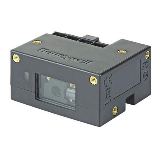
What is the CM Series 2D Imager Module The CM Series is a range of encased compact 2D imager mod- ules for fixed mount applications. The CM Series 2D imager module includes the following fea- tures: • USB interface (micro USB connector) •... - Page 3 CM Series 2D Imager Module Views Mounting holes (x10) Status indicator Exit Mounting window holes (x10)
- Page 4 Mounting holes (x10) USB cable Beeper Slider to secure cable Mounting holes (x10)
-
Page 5: Connecting To A Host
Connecting to a Host By default, the scanner is in USB serial interface. Remove slider from module by pressing the ends and slid- ing it off. Connect a standard USB cable (standard USB-A to micro USB) to the module. USB cable... - Page 6 Secure the cable to the module using the slider: Place the cable through the center of the slider. Press the ends of the slider and slide it back on to the mod- ule until tight. Connect the USB cable to the host. Power-up the host.
-
Page 7: Configuration Bar Codes
• Using the EZConfig Cloud for Scanning tool Configuration Bar Codes Scan configuration bar codes to set up your scanner. All avail- able configuration bar codes are available in the CM Series 2D Imager Module User Guide. Contact your local Honeywell OEM representative for more information. -
Page 8: Basic Setup
Basic Setup Here are some basic menu bar codes that may be useful for test- ing. For more setup options see the CM Series 2D Imager Mod- ule User Guide (available from your local Honeywell OEM representative). Note: The * symbol indicates the default value. -
Page 9: Beeper Volume
French German Italian Beeper Volume Medium... -
Page 10: All Symbologies
High * All Symbologies All Symbologies On All Symbologies Off... -
Page 11: Presentation Mode
Presentation Mode The scanner LEDs remain dim and aimer off until a movement is detected, then the aimer turns on and LEDs light up to read the bar code. There are 2 types: Presentation Mode or Presentation Mode— Extended Reading Range. Presentation Mode: Optimized scan speed, limited reading range. -
Page 12: Reset Factory Defaults
Streaming Presentation The scanner LEDs are on all the time (continuous) and the aimer is off until a movement is detected, then the aimer turns on to read the bar code. There are 2 types: Normal or Enhanced. Streaming Presentation—Normal: Fast scan speed, limited reading range. -
Page 13: Mechanical Dimensions
Mechanical Dimensions USB cable 13.2 24.4 Units are in millimeters. Tolerances: ±1.0 mm. -
Page 14: Mounting Holes
Mounting Holes Use M3 screws with a maximum depth of 5.8 mm/0.23 in. Max torque 4.5kgf.cm/3.9 lbf.in and pull out resistance 736N. 12.5 30.5 13.5 42.5 Units are in millimeters. Tolerances ±0.5 mm. - Page 15 Recommendations • Do not add an exit window over the existing exit window. • For best beeper performance, do not fully cover the beeper opening. • Be sure the cable is fitted tightly in the connector using the cable slider. The cable over mold should not be more than 23 mm/0.90 in.
-
Page 16: Limited Warranty
For patent information, see www.hsmpats.com. Trademarks Disclaimer Honeywell International Inc. (“HII”) reserves the right to make changes in specifications and other information contained in this document without prior notice, and the reader should in all cases consult HII to determine whether any such changes have been made.