Table of Contents
Advertisement
Quick Links
1.1 Inspection upon packing
Handle with care, not to give impact and vibration in case of unpacking. Please check
the contents of the package for quantity and damage occurred during transportation.
(Packing contents)
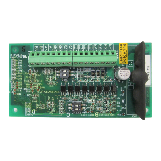
1. SJ-FB (Feed back board)
2. Instruction manual
3. Board bind screws (M3×8mm)
Please contact where you bought the unit as soon as possible when there is any prob-
lem.
1.2 Inquiry and Warranty of the Unit
1.2.1 Request upon inquiry
If you have any questions regarding damage of the unit, unknown parts or for general
inquiries please contact your supplier or the local Hitachi Distributor with the following
information.
(1) Inverter Model
(2) Production Number (MFG, NO)
(3) Date of Purchase
(4) Reason for Calling
Damaged part and its condition etc.
Unknown parts and their contents etc.
1.2.2 Warranty of the unit
The warranty period of the unit is shown below.
ü 1 year after normal installation.
However within the warranty period, the warranty will be void if the fault is due to;
(1) Incorrect use as directed in this manual, or attempted repair by unauthorized
personnel.
(2) Any damage sustained, other than from transportation (which should be re-
ported immediately).
(3) Using the unit beyond the limits of the specification.
(4) Act of God (Natural Disasters: Earthquakes, Lightning, etc)
The warranty is for the inverter only, any damage caused to third party equipment by
malfunction of the inverter is not covered by the warranty.
Any examination or repair after the warranty period (one year) is not covered. And
within the warranty period any repair and examination which results in information
showing the fault was caused by any of the items mentioned above,. the repair and ex-
amination cost are not covered. If you have any questions regarding the warranty
please contact either your supplier or the local Hitachi Distributor. Please refer to the
back cover for a list of the local Hitachi Distributors.
Chapter 1
: 1
: 1
: 2
1
GENERAL DESCRIPTIONS
Advertisement
Table of Contents

Related Manuals for Hitachi SJ-FB

Summary of Contents for Hitachi SJ-FB
- Page 1 If you have any questions regarding the warranty please contact either your supplier or the local Hitachi Distributor. Please refer to the back cover for a list of the local Hitachi Distributors.
- Page 2 This manual describes the application board SJ-FB for a SJ300 series inverter. This SJ-FB board, assembled in a SJ300 inverter, detected the rotation speed of a mo- tor with the encoder and feedback the motor speed to suppress speed fluctuations for highly accurate operation.
-
Page 3: Installation
Chapter 3 INSTALLATION How to Mount the option Board Please combine the hole at four corners of the option board to each guide post for op- tion positioning, and screw hole for the fixation of this side of the body. Then connect the option board, in option port 1 or 2 of side of the body as shown below. -
Page 4: Wiring And Connection
Chapter 4 WIRING AND CONNECTION 4.1 Terminal assignment of the Option Board Outlook of SJ-FB Dip switch SWR Dip switch SWENC Connector for Main body connection TM1 terminal assignment TM2 terminal assignment EP5 EG5 EAP EAN EBP EBN EZP EZN... - Page 5 Chapter 4 WIRING AND CONNECTION 4.2 Function Explanation of the Terminal Common electric Terminal Code Function terminal specification Pulse train input (see page 16) •Mode 0 : 90 degree phase difference pulse •Mode 2 : Forward pulse/Reverse pulse •Mode 1 : Forward/Reverse signal, pulse train DC5V receiver input Pulse line position ON/OFF of the terminal resistance on the option...
-
Page 6: Terminal Connection Diagram
Also, electric wire for the encoder uses twist shield line of 0.75mm or more (the example: Hitachi Cable, Ltd. KPEV-S), and make the distance less than 20m. In case of more than 20m, please use the relay amplifier of the 5V line driver specification output. - Page 7 (Note 5) : Isolate common signal for analog signal of the main body (L terminal of the logic card of SJ300) from common terminal of the SJ-FB. (Note 6) : Please connect the encoder signal line properly so that the relationship among their phases become as shown below during rotation of the mo- tor(Standard EG5).
- Page 8 Chapter 5 SETTING 5.1 Position of the setting switch Outlook of SJ-FB How to Set Switches SWENC SWENC and SWR [ON/OFF] Slide to the (OFF) marked side of the switch to turn it off and the opposite side to turn it on.
- Page 9 / 03(SLV) / 04(0Hz area SLV) / 05(V2) Auto-tuning mode 00(NOR : Invalid) / 01(NRT : not rotate)/ H001 selection 02(AUT : rotate) 00(Hitachi standard motor constant)/ motor constant H002 01(Auto-tuning data)/ selection 02(Auto tuning data with online auto-tuning) motor capacity...
- Page 10 Chapter 5 SETTING Change Setting Code Function name Setting range Initial data mode on run on run depends The 1 motor J setting 0.000 - 9.999 / 10.00 - 99.99 / 100.0 - on the H034 (Auto-tuning data) 9999.( kgm motor ca- pacity PI control propor-...
- Page 11 (P027) are set 0, the Abnormal detection data processing will be invalid. (Note 3): Regarding the SJ-FB setting, there are some warning about what type of main body combines with the SJ-FB which is written following list. Main body of SJ300 Production No (MFG No) (Note 4)
- Page 12 Chapter 5 SETTING Setting flowchart of the switch on the board START Detect a wire break of A, B phase signal? Set SWENC1 switch OFF. Set SWENC1 switch ON. Detect a wire break of the Z phase signal? Set SWENC2 switch OFF.
- Page 13 4. For speed control, operation is started when operation command of the inverter main body is turned on. 5. For position control, turn on the STAT terminal of SJ-FB and operation com- mand of the inverter main body first of all. Next input the pulse train position command to SAP-SAN and SBP-SBN.
- Page 14 Chapter 6 OPERATION (Note 6) : If satisfactory performance can not be obtained, please adjust the motor con- stant for the phenomena according to following table. Status Adjusting Phenomena Contents of adjustment running parameter The shock is oc- Set “Motor constant J” bigger and bigger At starting H024/H034 curred at starting...
-
Page 15: Orientation Function
Chapter 7 FUNCTIONS Relation code 7.1 Orientation function A044: 1 Control Method P014: Orientation Stop Position This board is provided with the orientation function used to P015: Orientation Speed setting position the motor at a certain point during operation. This P016: Orientation Direction setting P017: Completion range setting function can be used for replacing a component of the main... - Page 16 Chapter 7 FUNCTIONS 4. Inverter maintains the position after the completion, and outputs the ‘position control completion (POK) signal’ after the set value of ‘delay time setting (P018). (Inverter drives the motor reverse and return to the required stop position in the case it ex- ceeds the required stop position.) 5.
-
Page 17: Data Setting
Stoppage goal position is like shown in Figure 7-2 irrespective of the turn direction. (Note 4) : It depends on what type of main body combines with the SJ-FB, the setting value conversion is different. Please refer to the (Note 3) of the “5.3 Items re- garding the feed back board of the inverter main body“. -
Page 18: Control Mode Setting
Chapter 7 FUNCTIONS Data setting of the input-output terminal Input-output terminal Terminal assignment Contents Set up 45 to one of ORT terminal (ORT) ON : Orientation mode them of C001∼C008 Positioning comple- Set up 23 to one of Output when comes tion signal (POK) them of C021∼C025... - Page 19 Chapter 7 FUNCTIONS Master Inverter Slave Inverter AP,BP SAP,SBP AN,BN SAN,SBN EAP,EBP EAP,EBP EAN,EBN EAN,EBN Sub Motor Main Motor Figure 7-3 Wiring for Synchronized Operation (Note) : Please connect EG5 of the main and sub inverter together to avoid malfunction caused by EMC noise. 7.3.3 Data setting Data setting related to position control Setting item...
- Page 20 (N: Electronic gear ratio numerator, D: Electronic gear ratio denominator) (Note 4) : It depends on what type of main body combines with the SJ-FB, the setting value conversion is different. Please refer to the (Note 3) of the “5.3 Items regarding the feed back board of the inverter main body“.
- Page 21 Chapter 7 FUNCTIONS [Setting example] Main Motor : Encoder pulse 1024 pulses Sub Motor : Encoder pulse 3000 pulses (Main motor rotation speed) : (sub motor rotation speed) = 2 : 1 Set the following for slave inverter in this case. Electronic gear setting position (P019) : RET (command pulse side) Electronic gear numerator (P020)
- Page 22 Chapter 7 FUNCTIONS 7.3.4 Pulse train mode selection The following 3 ways of pulse line input can be selected by the setting of P013. 1) 90° phase difference pulse train (Mode 0) (Pulse train input) (Pulse train input) Detected pulse number Reverse Forward Time...
- Page 23 Chapter 7 FUNCTIONS Relation code Speed control (P/PI) switching A044: 1 Control Method P052: 1 Proportional gain function C001-C008: Intelligent input terminal Speed control mode is normally controlled by proportional- integration compensation (Pi), which keeps the deviation between the actual speed and speed command becomes 0. Further, you can also achieve a propotional control function, which can be used as drooping operation (i.e.
- Page 24 Chapter 7 FUNCTIONS 7.5 Compensation of secondary resistor function (Temperature revision) Relation code Please use this function, if you want to do the temperature P025: Compensation of secondary revision to restrain the speed fluctuation by the temperature resistor selection b098: Thermistor selection change of the motor.
- Page 25 (Note) : Inverter trips anyway in case of encoder line break error (E60, E70), SJ-FB ab- normal connection (E69,E79) occurs, although action selection is set to 01 (RUN). Please refer to "Chapter 5.2 FEED-BACK BOARD INITIAL SETTINGS".
-
Page 26: Product Specification
(Note 1): The main body setting or external input is selectable. SJ-DG (digital input option board) is required in case of external input. (Note 2): It depends on what type of main body combines with the SJ-FB, the setting value conversion is different.