Table of Contents
Advertisement
Advertisement
Table of Contents

Related Manuals for IAME MINI SWIFT 60CC - USA


Summary of Contents for IAME MINI SWIFT 60CC - USA
- Page 1 Installation MANUAL “MINI SWIFT 60 USA” CC - MAN-85 – USA...
-
Page 2: Table Of Contents
INDEX PAGE GENERAL DESCRIPTION OF THE ENGINE CHARACTERISTICS OF THE ENGINE – OPERATIONAL LIMITS 1- Contents of packing 2- Motor Identification Number 3- Preparation and installation of the engine on the chassis Installation sketch of the engine on the chassis Exhaust header assembly Preparation and installation of the motor-mount Install the carburetor... -
Page 3: General Description Of The Engine
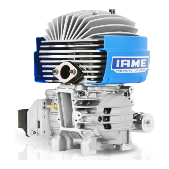
GENERAL DESCRIPTION OF THE ENGINE This engine of the TaG series (Touch and Go) has been expressly designed and developed for the powering of karts, either for hobby or racing, on closed tracks destined for this specific purpose. When designing this new line of engines, the technical solutions already adopted for the high performance engines were used, in order to guarantee the highest reliability and lasting of components, when the operating limits are respected. -
Page 4: Characteristics Of The Engine - Operational Limits
Operational limits: Max.RPM / 1’ : 14.500 RPM ATTENTION: Never exceed the above limits, no obligation of IAME exists in case the above limits are exceeded. 1- CONTENTS OF PACKING Each engine is supplied with the accessories under shown:... - Page 5 ACCESSORIES ELECTRIC WIRES BATTERY SUPPORTS EXHAUST GROUP NGK SPARK PLUG TILLOTSON HW-31A CARBURETTOR CLUTCH COVER COPERCHIO FRIZIONE SILENZIATORE DI ASPIRAZIONE INTAKE GROUP INTAKE SILENCER MAN-85 – USA...
-
Page 6: 2- Motor Identification Number
NOTE: In case of need for spare parts and when contacting the IAME Support Centers, please always refer to the Motor Identification Number and to the motor model. MAN-85 – USA... -
Page 7: 3- Preparation And Installation Of The Engine On The Chassis
3- PREPARATION AND INSTALLATION OF THE ENGINE ON THE CHASSIS NOTE: In case the engine is supplied already assembled on the chassis, it is at care of the assembler to follow these instructions. The final customer, in this case, can skip this section and can start reading from section 4. -
Page 8: Exhaust Header Assembly
EXHAUST HEADER ASSEMBLY NOTE: ENGINE SUPPLIED WITH EXHAUST GASKET AND NUTS ALREADY INSERTED , WHEN THE SHIPMENT IS MADE AN EXHAUST COVER GASKET IS PROVIDED TO PROTECT THE INTERNAL PARTS. 3.2.1 REMOVE NUTS AND EXHAUST COVER. 3.2.2 INSTALL SPRINGS ON THE EXHAUST Fig.1 HEADER (SEE FIG 1). -
Page 9: Preparation And Installation Of The Motor-Mount
PREPARATION AND INSTALLATION OF THE MOTOR-MOUNT NOTE: ALL THE DIMENSIONS ARE IN MILLIMETERS 3.3.1 DRILL 4 HOLES (DIAM. 8.5mm) INTO THE MOTOR-MOUNT . MOTOR-MOUNT HORIZONTAL VIEW 3.3.2 INSTALL THE MOTOR-MOUNT. MAKE Fig.4 SURE TO USE M8 ALLEN SCREWS WITH A LENGTH SUCH AS TO ENGAGE, IN THE CRANKCASE, THREADED... -
Page 10: Install The Engine On The Chassis
INSTINSTALL THE ENGINE ON CHASSIS 3.5.1 PLACE THE ENGINE ON THE 2 OUTSIDE MAIN RAILS AND FIX THE MOTOR-MOUNT WITH THE TWO CLAMPS (SEE FIG.12). SUGGESTION: NEVER TORQUE COMPLETELY THE CLAMPS UNTIL CHAIN INSTALLED PROPERLY ALIGNED. Fig.12 3.5.2 CHECK THE ALIGNMENT OF THE ENGINE SPROCKET AXLE... -
Page 11: Install The Clutch Cover With H.t. Coil
INSTALL THE CLUTCH COVER WITH H.T. COIL 3.6.1 REMOVE THE 3 SCREWS M6x30 ON THE CRANKCASE (SEE FIG. 16-A) AND INSTALL THE CLUTCH COVER WITH H.T. COIL (SEE FIG.16-B) TORQUE THE 3 SCREWS AT 8 ÷ 10 Nm (70 ÷ 90 In-lb) (5 mm ALLEN WRENCH) ATTENTION: MAKE SURE THAT THE COPPER GROUND... -
Page 12: Installation Electrical Connections
ELECTRICAL CONNECTIONS (refer to the attached electrical schematic) Fig.17 INSTALL THE CLAMPS ON THE BATTERY SUPPORT (SEE FIG.17). N°2 SCREWS M6x10 TORQUE SCREWS AT 8÷10 Nm (70 ÷ 90 in-lb) (12 POINT WRENCH 10 mm) Fig.18 3.7.1 POSITION THE SUPPORT ON THE CHASSIS REAR RAIL (SEE FIG.18). -
Page 13: Electrical Connections On The Engine
3.7.4 POSITION THE BATTERY ON THE Fig.21 SUPPORT (SEE FIG.21). SUGGESTION: NEVER CONNECT THE BATTERY UNTIL YOU ARE READY TO START THE ENGINE. ATTENTION PAY ATTENTION NOT TO SHORT CIRCUIT THE BATTERY TERMINALS AS BATTERY COULD BE DAMAGED BEYOND REPAIR. Fig.22 3.7.5 CONNECT THE STARTER RELAY TO THE CABLE TERMINALS (SEE FIG.22). - Page 14 3.8.2 CONNECT THE TERMINAL OF THE IGNITION STATOR TO THE H.T. COIL (SEE FIG.25). Fig.25 3.8.3 CONNECT THE SECOND TERMINAL OF THE IGNITION STATOR TO THE "MALE" CONNECTOR HARNESS (SEE FIG.26). Fig.26 3.8.4 FIX THE HARNESS WITH PLASTIC CLAMPS, ALONG THE CHASSIS REAR RAIL (SEE FIG.27).
- Page 15 Fig.29 3.8.6 FIX THE STARTER RELAY TO THE FIXING STRAP BY MEANS OF A CLAMP, OR FIX IT TO THE BATTERY SUPPORT WITH THE BIADHESIVE TAPE (SEE FIG.29). ATTENTION : NEVER LET THE HARNESS GET IN TOUCH WITH THE GROUND OR WITH ROTATING PARTS COULD DAMAGED...
- Page 16 Fig.33 3.8.10 CONNECT BUTTON CONNECTORS WITH HARNESS CONNECTORS (SEE FIG.33). ATTENTION : ATTENTION MATCH CONNECTORS ACCORDING CORRESPONDING COLOUR IN ORDER TO CONNECT THEM PROPERLY. Fig.34 3.8.11 TIGHTEN THE SPARK PLUG CAP ON THE H.T. COIL CABLE (SEE FIG. 34). Fig.35 3.8.12 FIX THE SPARK-PLUG CAP ON THE H.T.
-
Page 17: Install The Intake Silencer
Fig.36 3.8.13 MAKE SURE THAT THE BATTERY IS PROPERLY CONNECTED BEFORE STARTING THE ENGINE. (SEE FIG. 36). INSTALL THE INTAKE SILENCER Fig.37 MAKE SURE THAT THE AIR FILTER INLET HOLE TOWARDS UPPER SIDE AND THAT IT IS NOT PLUGGED. TIGHTEN THE FIXING CLAMP ON THE CARB. -
Page 18: 4- Gasoline And Oil
4- GASOLINE AND OIL Use (leaded) or unleaded gasoline, mixed with oil at 6% (16:1). Use oil containing Castor Oil which guarantees an optimized lubrication at high temperatures. As on the other hand, use of Castor Oils creates gummy residues which give origin to carbon deposits, it is necessary to check and clean, at least every 5 ÷10 hours, the piston and the head. -
Page 19: 5- Tillotson Hw-31A Carburettor Adjustment
5-TILLOTSON HW-31A CARBURETTOR ADJUSTEMENT ( L ) LOW SPEED FUEL ( I ) TROTTLE MIXTUREREGIMI SPEED SCREW ( H ) HIGH SPEED FUEL MIXTURE REGIM LEAN RICHE 1 T.O. ¼ ¾ T.O. T.O. ½ T.O. = TURNS OPEN T.O. Normally the correct setting of the mixture screws, after engine run-in, is the following: ... -
Page 20: 6- Starting And Stopping The Engine
6- STARTING AND STOPPING THE ENGINE Press the green button on the steering wheel to start the engine. If the engine cannot be started, stop and try again (check that gas gets into the carb.). Short and frequent tries are better than long ones. In case the engine can't be started, refer to the Sect. -
Page 21: 10- Centrifugal Clutch
10- CENTRIFUGAL CLUTCH The engine has a low maintenance dry centrifugal clutch. The following prescriptions, if carefully followed, will allow a long clutch life. When starting the engine, make sure that the brake pedal is fully pressed to avoid sudden accelerations. ATTENTION: Once the engine is started and kart is still, avoid useless accelerations which can overheat and deteriorate the clutch, before time. -
Page 22: 11- Instructions For The Disassembly /Assembly Of The Clutch
11- INSTRUCTIONS FOR THE DISASSEMBLY / ASSEMBLY OF THE CLUTCH ATTENTION: The following operations can be performed by a skilled mechanic under the condition to have available the dedicated tools shown on the text, otherwise it is necessary to apply to an Authorized Service Center. Refer to the following drawing during the operations 1 Drum nut 5 Screw... - Page 23 Before assembling the clutch, wash with diluent the shaft taper, the connecting hole on the clutch body, the clutch drum and the starter ring. Clutch assembly Install the starter ring on the clutch body 12 Point wrench - 10 mm ...
-
Page 24: 12- Battery
12- BATTERY The battery (12 V – 7.2 Ah) is sealed and without maintenance. In order to lenghten the battery life it is necessary though to follow a few recommendations . When tension drops below 12.6V it is necessary to recharge the battery. Max allowed recharging current is 1.8A. -
Page 25: 13- Use Of The Battery Charger
P.N. A-120910 (not included in the supply). This battery charger, which has been expressly selected by IAME for its characteristics, operates at 220V, is easy to use, and, automatically switches off when the charging is over. -
Page 26: 14- Spark-Plug And Thermal Degree
14 –SPARK-PLUG THERMAL DEGREE The engine is supplied with a standard NGK BR10EG spark plug which represents a good compromise between the needs of a good break-in and the racing needs in normal conditions. Use of different spark plugs is possibile and, as a general information, we are attaching a correspondence list among spark plugs of other brands, based on thermal degree, which represents the capacity of the spark plug to dissipate the internal heat. -
Page 27: 15- Choice Of The Best Sprocket Ratio
The operating limit for the 60 MINI SWIFT engine is 14.500 RPM. ATTENTION: Never exceed the above limit. No obligation of IAME exists in case the above limit is exceeded. In case the user wishes to optimize on the track the sprocket ratio in order to achieve the best possibile performance, without abusing the engine, follow the under shown recommendations. - Page 28 Assume to use the engine with Z=11 teeth sprocket and that during the preliminary tests a Z=72 teeth axle sprocket has been used. From Table 1 with Z=11 as engine sprocket and Z=72 on the axle sprocket, a ratio of 6.55 is found. ...
-
Page 29: 16- Scheduled Maintenance
16- SCHEDULED MAINTENANCE Following some simple maintenance standards will allow to perform more reliably and guarantee a longer engine life. SCHEDULE COMPONENTS ACTIONS AND COMMENTS Before using Exhaust Check status and fixing Engine sprocket Check wear Check alignment with axle sprocket Engine chain Check wear, tensioning and oil... -
Page 30: 17- Troubleshooting
17- TROUBLESHOOTING Below are some common faults, their probable causes and suggested remedy . Faults Probable causes Remedy Starter will not crank when Bad connections on starter cables. Check and tighten pushing the start button Bad grounding of wiring loom Check connections and tighten Damaged cables Replace... -
Page 31: 18- Engine Preservation
18- ENGINE PRESERVATION When engine has to remain unoperative for a long period it must be preserved as follows : Disconnect the battery and charge it periodically (see sect. 12). Disconnect carburetor and clean it. Seal with tape the engine inlet and exhaust. The external of the engine must be cleaned. -
Page 32: Wiring Diagram
MAN-85 – USA...