Advertisement
Quick Links
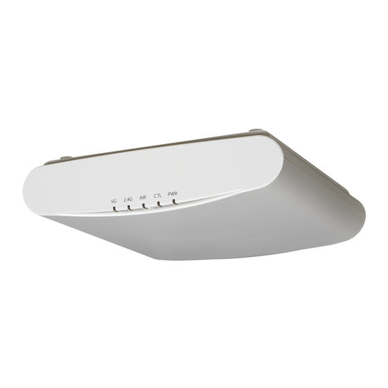
R610 Access Point
Quick Setup Guide
This Quick Setup Guide provides step-by-step instructions
on how to set up your Ruckus Wireless R610 Dual Band
802.11ac Multimedia Wi-Fi Access Point. After completing
the steps described in this Guide, you will be able to place
the Access Point (AP) at your site and provide wireless
network access to users.
Note: The R610 requires a minimum of ZoneDirector ver-
sion 9.13.2 or later, or SmartZone firmware version 3.4.1
or later.
T
G
O
L
HIS
UIDE IN
THER
ANGUAGES
•
请从以下网站获得该指南的简体中文版
https://support.ruckuswireless.com.
•
Vous trouverez la version française de ce guide à l'adresse
suivante https://support.ruckuswireless.com.
•
このガイ ドの⽇本語版は https://
support.ruckuswireless.com
でご覧 く だ さ い。
•
이 가이드의 한국어 버전은 웹 사이트
(https://support.ruckuswireless.com) 에서 확인하시기 바
랍니다 .
•
Veja a versão em português (Brasil) deste guia em
https://support.ruckuswireless.com.
•
Puede ver la versión en español (América Latina) de esta
guía en https://support.ruckuswireless.com.
B
Y
B
EFORE
OU
EGIN
Before deploying Ruckus Wireless products, please check for
the latest software and the release documentation.
•
User Guides and Release Notes are available at
http://support.ruckuswireless.com/documents
•
Software Upgrades are available at
http://support.ruckuswireless.com/software
•
Software License and Limited Warranty are available at
http://support.ruckuswireless.com/warranty
Copyright © 2019 CommScope, Inc. All rights reserved.
Published November 2019, Part Number 800-71238-001 Rev D
P
C
ACKAGE
ONTENTS
•
R610 Access Point
•
One wall-mount anchor kit, including two 1" No. 8 steel pan-
head Phillips sheet metal screws, one 5mm M2.5 x 1.06 Torx
security screw, and wall-mount anchors
•
One external T-bar bracket (two unassembled parts)
•
One unit removal pin
•
Regulatory flyer
•
Product warranty statement
•
Declaration of Conformity, if required
•
This Quick Setup Guide
S
1: C
TEP
OLLECT
MENTS
•
A computer running Windows 7, 8, 10 or Mac OS X (proce-
dures for other OS's are similar)
•
Two Cat 5e Ethernet cables
•
No. 2 Phillips screwdriver and T8 Torx driver for wall mount-
ing anchor kit
•
An AC power adapter (sold separately), or
•
An 802.3af or 802.3at -compliant Power over Ethernet (PoE)
switch or PoE injector
•
When mounting the R610 to a truss or pole, two customer-
supplied cable ties
IMPORTANT!
SmartZone controller, then refer to the ZoneDirector or
SmartZone Quick Setup Guide and connect the AP to your
local network.
S
2: C
TEP
ONNECT THE
Figure 1: Top view
.
1
After removing your Ruckus Wireless AP from its pack-
.
age, place it next to your computer.
2
Using an Ethernet cable, connect your computer's net-
.
work port to one of the two ports on the AP.
T
S
R
OOLS AND
ETUP
EQUIRE
If the AP is deployed with a ZoneDirector or
AP
Y
C
TO
OUR
OMPUTER
3
Using an AC adapter (sold separately), connect the AP
12VDC port to a protected power source.
Alternatively, connect the PoE port to a PoE injector or
switch for both power and network connections.
4
Verify that the Power LED on the external enclosure is a
steady green.
Figure 2: Bottom view
-
S
3: P
Y
TEP
REPARE
OUR
S
ETUP
Note: The following procedures assume Windows 7 as the
operating system. Procedures for other OS's are similar.
1
On your Windows 7 computer, configure your network
adapter from the Local Area Connection settings as fol-
lows:
•
Start > Control Panel > Network and Internet >
Network and Sharing Center >
Change Adapter Settings
2
Edit the TCP/IPv4 address settings as follows:
•
Local Area Connection > Properties > Internet
Protocol Version 4 (TCP/IPv4) > Properties
The TCP/IPv4 Properties dialog box appears.
Important!
Write down all of the currently active settings so
you can restore your computer to its current configuration
later (when this process is complete).
3
Select Use the following IP address (if it is not already
selected) and then make the following entries:
•
IP address: 192.168.0.22 (or any address in the
192.168.0.x network)
•
Subnet mask: 255.255.255.0
•
Default gateway: 192.168.0.1
Leave the DNS server fields empty.
4
Click OK to save your changes.
Your changes are put into effect immediately.
C
AP
OMPUTER FOR
Page 1 of 4
Advertisement

Related Manuals for Arris Ruckus R610


Summary of Contents for Arris Ruckus R610
- Page 1 Using an AC adapter (sold separately), connect the AP ACKAGE ONTENTS 12VDC port to a protected power source. • R610 Access Point Alternatively, connect the PoE port to a PoE injector or • One wall-mount anchor kit, including two 1" No. 8 steel pan- switch for both power and network connections.
- Page 2 their wireless network connection application. Congratulations! Your wireless network is active and ready 4: L NTO THE for use. Click Update Settings to save your changes. As specified earlier, the AP should be directly connected to Repeat Steps 4-7 for each Wireless # interface that you your computer (through one of the Ethernet ports) and want to enable.
- Page 3 Removing an External Bracket from a T-Bar Figure 8. Attaching the AP to the T-bar Mounting on a Recessed Drop-Ceiling T-Bar Move the ceiling tiles out of the way. Slide the locking tab away from the T-bar to release Note: This mounting bracket can also be used on a flush the AP-bracket assembly from the T-bar.
- Page 4 Mounting Template (Page 4 of 4) Copyright © 2017 Ruckus Wireless, Inc. Published April 2017, Part Number 800-71238-001 Rev C...