Table of Contents
Advertisement
Quick Links
Advertisement
Table of Contents

Related Manuals for GE PowerVac


Summary of Contents for GE PowerVac
- Page 1 DEH 40368 Instructions PowerVac Vacuum Circuit Breaker ® with ML-20 Mechanism...
-
Page 2: Table Of Contents
........17 A. Equipment Packages ..........5 11.1 General ................17 B. Inspecting for Damage ..........5 11.1.1 PowerVac Interrupter ............17 C. Filing a Claim ............. 5 11.1.2 Trouble Reporting ............17 Handling ................6 11.2 Service Conditions ............17 Storage................ - Page 3 6 Control Device and Voltage............. 18 Rating interference plate............6 Measurements ............... 35 Front view of PowerVac breaker without front cover ....8 Adjustments................35 Manual charging................ 9 Gag plate installation ..............10 Operating rod assembly ............10 Contact gap ................
-
Page 4: Section 1-Introduction
1. ALL CONDUCTORS MUST BE ASSUMED TO BE ENERGIZED It is the GE recommendation that, until the user has accumulated UNLESS THEIR POTENTIAL HAS BEEN MEASURED AS enough experience to select a test interval better suited to the... -
Page 5: Section 2-Description
The ML-20 mechanism is of the stored-energy type and use a gear motor to charge a closing spring. During a closing operation, ® This section contains a description of the PowerVac vacuum the energy stored in the closing spring is used to close the circuit breaker. -
Page 6: Storage
Figure 2 Rating interference plate 1. Rating interference plate 2. Lifting locations (3/4” dia. hole at all four corners) Figure 1 Front view of PowerVac breaker with front cover 4.2.2 Closing Spring Interlock This racking-track operated interlock (4, Figure 18) prevents 1. -
Page 7: Negative Interlock
4.2.3 Negative Interlock breaker contacts are in the closed position. If the breaker is in the “CONNECT” or “DISCONNECT/TEST” position in the The function of this racking-track operated interlock (5, Figure metalclad the détente angle locks into the racking mechanism 17) is to remove the trip latch from the trip roller thereby to prevent access to the hex section of the racking screw. -
Page 8: Section 5-Operation
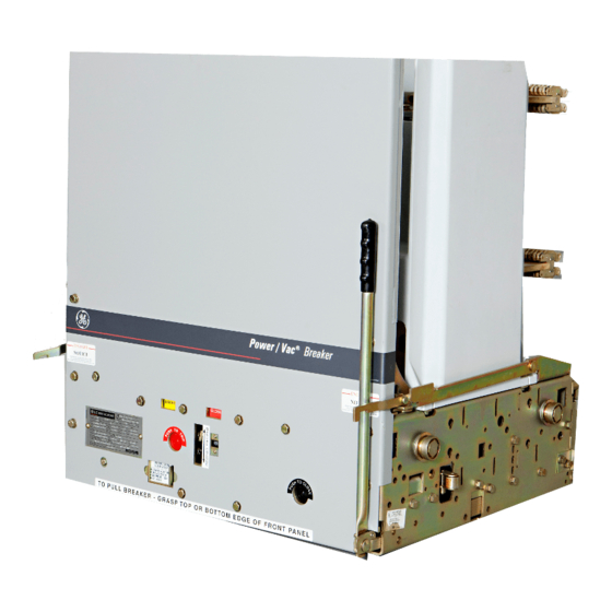
(2, view B). A manual charging system (3, view A) is provided so that the mechanism can be slow closed and the closing spring can be charged without electrical control power. Figure 3 Front view of PowerVac breaker ® Spring charging is accomplished electrically by a rotating... -
Page 9: Opening Operation
(23, view B), the trip latch (19, view D) is rotated, permitting the linkage to collapse and the vacuum SECTION 6—Electric Control circuit A typical PowerVac ® circuit breaker ML-20 mechanism wiring open and opens when the breaker is closed. During a close diagram is shown in Figure 16. -
Page 10: Closing Spring Gag
interference preventing use of the lift truck and racking of the breaker element. No attempt should be made to alter, modify or otherwise make inoperative this safety feature. With the gag plate in position, depress the manual close button. This action will partially discharge the closing spring and also partially close the vacuum interrupter contacts. -
Page 11: Section 8-Dimensional Checks
SECTION 8—Dimensional Checks With the breaker closed and the gag plate installed, perform the tape near the top on all three poles. It is also advisable to the following dimensional checks. put a reference mark on the tape to identify to which pole the tape is applied. -
Page 12: Close Coil Plunger Gap
8.4—Close Coil Plunger Gap 8.5—Trip Coil Plunger Gap The close coil plunger gap is shown in Figure 8. With the The trip coil plunger gap is shown in Figure 9. With the closing spring discharged, operate the plunger to make certain breaker in the open position and the closing spring in the that the plunger moves freely over its full stroke in the coil. - Page 13 Figure 10 Control switches LCS Switch...
-
Page 14: Section 9-Electrical Checks
SECTION 9—Electrical Checks Electrical checking consists of electrical breaker operation machine from this wire to ground. Increase the voltage to primary and secondary wiring high-potential testing (if 1125 volts (rms) 60 Hz and maintain for 60 seconds. Reduce required), primary circuit resistance (if required). Interrupter the voltage to zero and remove the hipot machine from the high-potential testing, and insulation resistance to ground. -
Page 15: Insulation Test
MUST NOT NOT BE USED TO TEST VACUUM INTERRUPTERS. other suitable megohmeter. THE CAPACITANCE OF THE POWERVAC BOTTLES IS VERY LOW AND THE LEAKAGE IN THE RECTIFIER AND ITS DC Since definite limits cannot be given for satisfactory insulation VOLTAGE MEASURING EQUIPMENT IS SUCH... -
Page 16: Section 10− − − − Checking And Installing
DISCONNECT position. During the first three turns, the spring min. to 29.857” max. Check that the breaker is OPEN and that discharge interlock should discharge the closing spring and the closing spring is DISCHARGED. Install the PowerVac ® the breaker contacts should remain OPEN. (If adjustment is circuit breaker into the DISCONNECT/TEST position in the required see MECHANICAL ADJUSTMENTS sections 16.7 and... -
Page 17: Section 11-Maintenance
However, fault current interruptions at or near the breaker 11.1—General rating may result in appreciable contact erosion. With frequent PowerVac ® circuit breakers have been designed to be as fault interruptions it is necessary to perform maintenance maintenance-free as practicable. -
Page 18: Lubrication
11.8—Lubrication 11.9—Recommended Maintenance Proper lubrication is important for maintaining reliable circuit The following operations should be performed at each breaker performance. The ML-20 mechanism uses bearings maintenance check: which have a synthetic lining in some locations. These Perform a visual inspection of the breaker. Check for bearings do not require lubrication to maintain low friction, but loose or damaged parts. -
Page 19: Section 12-Timing
Optional, travel recorder linkage can be checked by tripping a charged breaker open while be obtained through your local GE Sales Office by ordering maintaining a close signal. part number 0144D1235G002. A typical travel trace and interpretation are shown in Figure 11. -
Page 20: Section 13-Opening And Closing Speed
SECTION 13—Opening and Closing Speed The opening speed is modified by moving the spring adjusting The operating speeds for a 5 cycle breaker are as follows: nuts on the opening spring assemblies. A change in opening speed affects the closing speed. Reference Figure 12. Operation Operation Operation... -
Page 21: Section 14-Repair And Replacement
Retaining rings can be obtained from your local mounting bolts. Set the pole assembly so that the GE Sales Office by ordering part number 0282A2015G001. distance between the primary studs and the studs on the adjacent pole is ten (10) inches center line to center line. -
Page 22: Closing Coil Replacement
Perform the operation in the following sequence: direction of the index mark on the end of the shaft and the position of the operating link in relation to the stop screw. Charge closing spring and install gag plate. Remove mounting hardware securing auxiliary switch to Depress the close and then the trip buttons. -
Page 23: Section 15-Renewal Parts
SECTION 15—Renewal Parts Renewal Part numbers are available from your local GE Sales office. It is recommended that sufficient renewal parts be carried in 15.1—Ordering Instructions stock to enable the prompt replacement of any worn, broken or damaged parts. A stock of such parts minimizes service... -
Page 24: Trip Coil Plunger
Reference DIMENSIONAL CHECKS for breaker position and The breaker should be open with the closing spring charged. spring status. Back off 1/4 inch linkage adjusting screw. 16.5—Close Coil Plunger While holding roller at 0.995 inch dimension, advance To adjust the close coil plunger gap, Figure 8, lift locktab away adjusting screw to just touch interlock lever. - Page 25 Figure 14 Toggle linkage positions of the ML-18 mechanism (Viewed from right side) Continued on next page (A) Breaker open - spring discharged Output crank Jackshaft Trip latch Trip roller Closing roller Trip link 7a. Closing toggle 7b. Closing toggle Prop Closing cam Prop spring...
- Page 26 Figure 14 Continued (C) Breaker closed - spring discharged (D) Breaker closed - spring charged...
- Page 27 Figure 15 Schematic of ML-20 mechanism 1. Close spring 12. Output crank 2. Cam shaft 13. Cross shaft 3. Manual charge 14. Bell cranks 4. Charging arms 15. Opening springs 5. Ratchet wheel 16. Wipe springs 6. Driving pawl 17. Auxiliary switch 7.
- Page 28 Figure 15 Continued Partial View A Partial View B Partial View C Partial View D Partial View D...
- Page 29 Figure 16 Typical wiring diagram for ML-20 mechanism...
- Page 30 Figure 17 PowerVac breaker left-front view 1. Gag interlock angle 2. Track rollers 3. Positive interlock bar 4. Closing spring discharge roller 5. Negative interlock roller 6. Rating interference plate 7. Front cover 8. Racking engagement lever 9. Secondary coupler ...
- Page 31 Figure 19 Trip coil and linkage 1. Trip coil 2. Closing spring 3. Trip linkage adjusting rod and nut...
- Page 32 Figure 20 Close coil linkage 1. Close linkage adjusting nut 2. Close linkage adjusting rod 3. Link to close latch actuator...
- Page 33 Figure 21 Bottom view of ML-18 mechanism 1. Closing spring 10. Pivot bolt 2. Opening springs 11. Interlock bracket 3. Auxiliary switch 12. SM/LS motor control switch 4. Spring charging motor 13. LCS latch checking switch 5. Trip coil 14. CL/MS close latch monitor switch 6.
- Page 34 *Install rivet in aligned holes with interlock roller, set at .670 and striker making contact with adjusted trip coil rod. CAUTION: This is a safety feature not a routine maintenance item Figure 22 Negative interlock A change in the setting of the close latch stop bolt will affect the adjustment of the spring discharge interlock Figure 23 Spring wipe...
- Page 35 TABLE 2 MEASUREMENTS ITEM BREAKER CL. SPRING OP. SPRING MEASUREMENT CONTACT OPEN CHARGED DISCHARGED MEASURED BETWEEN BELLVILLE WIPE CLOSED CHARGED CHARGED WASHER AND TRUNION CONTACT OPEN CHARGED DISCHARGED MEASURE THE TRAVEL OF THE CLOSED CHARGED CHARGED OPERATING ROD INSULATOR CONTACT EROSION CLOSED DISCHARGED...
-
Page 36: Index
General 17 Lubrication 18 Safety 4 Description 5 Mechanism 17 Safety Precaution 6 Dimensional Checks 11 PowerVac Interrupter 17 Secondary Circuit 14 Close Coil Plunger Gap 12 Primary Insulation Parts 17 Service Conditions 17 Close Coil Linkage 32 Service Conditions 17... -
Page 37: Trouble Reporting Form
USER REPORT NO. FAILURE REPORTING FORM FOR POWER CIRCUIT BREAKERS Check all appropriate blocks and provide information indicated. For major trouble provide additional information requested on back of page supplemented with additional pages if necessary. User Ident EQUIPMENT: Station____________________________ of Breaker___________________ Equipment Nameplate Mfgr._______________________________Type_______________ Serial #_____________________ Information... - Page 38 ADDITIONAL INFORMATION REQUIRED FOR ANALYSIS OF MAJOR OR SYSTEM RELATED FAILURE (USE ADDITIONAL PAGES AS NECESSARY) Single line station diagram showing involved breakers Operation and timing sequence (including all alarms) of this and related breakers from last time that conditions were definitely normal Line conditions before, during, and after failure Oscillograms - attach with explanation &...
- Page 39 Intentionally Left Blank...
- Page 40 Should further information be desired or should particular problems arise which are not covered sufficiently for the purchaser's purposes, the matter should be referred to the General Electric Company. GE Electrical Distribution & Control General Electric Company Switchgear Business Department...