Table of Contents
Advertisement
Quick Links
Operator's manual
GB
Please read the operator's manual carefully and make sure
you understand the instructions before using the machine.
Manual de
ES
instrucciones
Lea detenidamente el manual de instrucciones y asegúrese
de entender su contenido antes de utilizar la máquina.
Bedienungsanweisung
DE
Lesen Sie die Bedienungsanweisung sorgfältig durch und
machen Sie sich mit dem Inhalt vertraut, bevor Sie das
Gerät benutzen.
Manuel d'utilisation
FR
Lire attentivement et bien assimiler le manuel d'utilisation
avant d'utiliser la machine.
DS50
AT/ATS
DS70
HUSQVARNA CONSTRUCTION PRODUCTS
AT
GB ES DE FR
Advertisement
Chapters
Table of Contents

Related Manuals for Husqvarna DS50 AT


Summary of Contents for Husqvarna DS50 AT
- Page 1 Lesen Sie die Bedienungsanweisung sorgfältig durch und machen Sie sich mit dem Inhalt vertraut, bevor Sie das Gerät benutzen. GB ES DE FR Manuel d’utilisation Lire attentivement et bien assimiler le manuel d’utilisation avant d’utiliser la machine. HUSQVARNA CONSTRUCTION PRODUCTS...
-
Page 2: Key To Symbols
KEY TO SYMBOLS Symbols on the machine: Symbols in the operator’s manual: WARNING! The machine can be a Inspection and/or maintenance should dangerous tool if used incorrectly or be carried out with the motor switched carelessly, which can cause serious or fatal off and the plug disconnected. -
Page 3: Table Of Contents
CONTENTS Contents KEY TO SYMBOLS Symbols on the machine: ..........Symbols in the operator’s manual: ....... CONTENTS Contents ..............WHAT IS WHAT? What is what on the stand? ......... SAFETY INSTRUCTIONS Steps before using a new stand ........Personal protective equipment ........General safety precautions .......... -
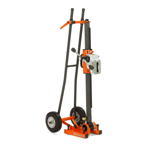
Page 4: What Is What
WHAT IS WHAT? What is what on the stand? 1 Locking screw 17 Expansion attachment 2 Spirit level 18 Drill column 3 Locking screw, locking clamp 19 Stop washer 4 Feeder housing lock 20 Locking clamp for quick mounting 5 Locking screw drill column 21 Mounting for feed lever 6 Position ring 22 Clamping screws for glide plates... -
Page 5: Safety Instructions
• Heavy-duty, firm grip gloves. Let your Husqvarna dealer regularly check the machine and make essential adjustments and repairs. All information and all data in the Operator’s Manual were applicable at the time the Operator’s Manual was sent to print. -
Page 6: General Safety Precautions
SAFETY INSTRUCTIONS General safety precautions General working instructions • Please read the operator’s manual carefully and make sure you understand the instructions before using the machine. Basic safety rules WARNING! There is always a risk of crush • Do not use the machine in bad weather, such as dense injuries when working with products fog, rain, strong wind, intense cold, etc. -
Page 7: Presentation
Husqvarna Construction Products has a policy of continuous product development. Husqvarna reserves the right to modify the design and appearance of products without prior notice •... -
Page 8: Stabilizer
PRESENTATION Accessories • Water collector • Quick mounting for automatic feed unit (both sides of feeder housing) • Retaining ring • Expander • Distance • Stabilizer For extra support. 8 – English... -
Page 9: Assembly
ASSEMBLY Assembling the stand Assembly of drill motor 1 Lock the feeder housing on the drill column with the lock handle. 1 Drill holes (15 mm) in the floor or in the wall and knock in the expander bolts. 2 Loosen the locking screw for the locking clamp. 2 Screw the base plate tight. -
Page 10: Before Drilling
ASSEMBLY Before drilling WARNING! Before drilling, check that all locking screws are tightened well. Serious accidents can occur if the concrete core remains in the drill when backing out the drill motor/drill from the floor, wall or ceiling. WARNING! If the vacuum plate is used, make sure the support surface is not porous and can loosen from the floor or the wall. -
Page 11: Maintenance
MAINTENANCE Stand maintenance 3 Loosen the adjustment screws. The lifetime of your machine can be extended considerably if it is used, cared for and maintained in the proper manner. 4 Loosen 2*4 clamping screws for the glide plates. IMPORTANT! All types of repairs may only be carried out by authorised repairmen. -
Page 12: Technical Data
TECHNICAL DATA Dimensions DS50 DS70 DS50 ATS DS50, mm/inch DS70, mm/inch 438/17,2 438/17,2 320/12,6 340/13,4 526/20,7 546/21,5 235/9,3 265/10,4 971/38,2 1026/40,4 1140/44,9 1205/47,4 177/7,0 231/9,1 1158/45,6 450/17,7 Stroke , mm/inch --------------------- Expander ------------- Max. drill diameter, mm/inch DS50 DS70 DS50 0-676/0-26,6 Track width, mm/inch DS50 350 DS70 0-757/0-29,8... -
Page 13: The Column's Angling
TECHNICAL DATA The column's angling 360° Weight DS50, kg/lbs DS70, kg/lbs Drill column 6,7/14,7 9,1/20,0 Feeder housing 7,8/17,2 9,7/21,3 Quick mounting 0,6/1,3 0,6/1,3 Feed lever 0,8/1,8 Feed lever 0,8/1,8 Base plate 9,2/20,2 12,0/26,4 Transport wheels 4,1/9,0 4,1/9,0 Total weight without 29,2/64,2 36,3/79,9 stabilizer... -
Page 14: Ec-Declaration Of Conformity
Husqvarna Construction Products, SE-433 81 Partille, Sweden, tel: +46-31-949000, declares under sole responsibility that the stands Husqvarna DS50AT and DS70AT from 2007’s serial numbers and onwards (the year is clearly stated in plain text on the type plate with subsequent serial number) are in conformity with the requirements of the COUNCIL’S DIRECTIVES: - of June 22, 1998 ”relating to machinery”... - Page 15 www.husqvarnacp.com 1150979-20 ´®z+RLT¶07¨ 2007-09-26 ´®z+RLT¶07¨...