
Summary of Contents for Faulhaber PRECIstep AD CM M1S
- Page 1 Stepper Motor DRIVER Constant Current Mode USER MANUAL AD CM M1S AD CM M2S AD CM M3S...
- Page 2 User manual AD CM M Page 2 of 20 Release tracking File Description Date V4900UM240904_CD first tracked version 24.09.2004 V4900UM240205_DC Release with new product 24.02.2005 V4900UM051005_CD Updated PIN-out info and safety notice 05.10.2005 V4900UM241105_CD-R1 Correction of optional cable part number 24.11.2005 V4900UM161205_CD-R2 Correction of suitable motors...
-
Page 3: Table Of Contents
User manual AD CM M Page 3 of 20 Contents GENERAL INFORMATION ...................................... 4 .............................. 4 RODUCT ESCRIPTION 1.1.1 Available versions ................................ 5 .............................. 5 ECHNICAL PECIFICATIONS .......................... 6 ROTECTION OF NPUTS AND UTPUTS PRECISTEP ............................ 7 UITABLE ... -
Page 4: General Information
User manual AD CM M Page 4 of 20 General Information 1.1 Product Description The main interest of the use of a current mode driver such as the AD CM models is the current control independent from the supply voltage (chopper). This allows to apply a much higher voltage than needed to drive the current without risk of overheat. -
Page 5: Available Versions
User manual AD CM M Page 5 of 20 1.1.1 Available versions The AD CM M_S is available in three different versions AD CM M1S (Standard stock item) Basic driver, requiring only clock and direction signals, it is destined to be controlled by a PC or any other host. -
Page 6: Protection Of Inputs And Outputs
User manual AD CM M Page 6 of 20 It is designed to drive the small stepper motors in full step or half step, one phase-on or two phase-on, clockwise or counter clockwise. AD CM M1S AD CM M2 AD CM M3S Power supply voltage Power supply current Motor Output current... -
Page 7: Suitable Precistep Motors
User manual AD CM M Page 7 of 20 1.4 Suitable PRECISTEP Motors The driver of the series AD CM M_S is specifically suitable for motors with windings designed for constant current control. Motor Type Winding Current setting Voltage setting (switch position) (recommended) AM0820... -
Page 8: Dimensions And Mounting
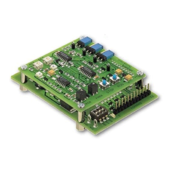
User manual AD CM M Page 8 of 20 1.5 Dimensions and mounting The drivers can be mounted by using the four holes on the board. However, the M2 and M3 consist of two boards assembled through these holes, which means that you have to fix the driver by using 4 screws M2.5. 4x O2,7 53.5 12.0... -
Page 9: Set-Up And Installation Of Ad Cm M1S
User manual AD CM M Page 9 of 20 Set-up and installation of AD CM M1S This section refers to all functions offered by the stepper motor driver type AD CM M1S. The set-up of the M2S and M3S version is the same, relatively to the functions of the M1S, but offers some additional functionalities. 2.1 Block Diagram Host Translator... -
Page 10: Command Connector
User manual AD CM M Page 10 of 20 Note Both M2S and M3S versions can be used as M1S version if the jumpers ADJ, VCO and CK on the mezzanine board are removed (see section 3 and 4 for more information about the jumpers). 2.3.1 COMMAND connector Input voltage for all inputs varies from 5 to 24VDC This 12-pins connector is available on all driver versions, it provides access to all functionality. - Page 11 User manual AD CM M Page 11 of 20 PIN3 Direction of rotation The signal can be changed at any time but it takes effect after the next following clock pulse. If the clock and direction signals are triggered at the same time, the step execution will change immediately. Warning: As PIN1 to 3 are high-active inputs, the switches for operation mode (see section 2.3.2) must all be in the OFF position so that they can be activated.
-
Page 12: Switch For Operation Mode
User manual AD CM M Page 12 of 20 HOME is a function needed to know the commutation position of the driver. It is activated every time Phase A of the motor is energized with positive current. This helps to home the clock of the host to the driver commutation, a function helpful to avoid step losses when power to the driver is lost. -
Page 13: Motor A/Power Supply + Motor
User manual AD CM M Page 13 of 20 2.3.4 Motor A/Power Supply + Motor The driver comes with a screw type terminal for the connection of the power supply and the motor. Pin # Function Motor PIN Phase B - Phase B + Phase A - Phase A +... -
Page 14: Set-Up Of The Ad Cm M2S
User manual AD CM M Page 14 of 20 Set-up of the AD CM M2S This driver version includes the function of the AD CM M1S and additionally offers a mezzanine (plug-in) board with the following characteristics: • On-board clock generator •... -
Page 15: Operation Of The Ad Cm M2
User manual AD CM M Page 15 of 20 • Turn FMIN potentiometer CCW to zero • Set Jumper ADJ to position A • Set Jumper VCO to position A • See whether the motor starts and adjust FMIN potentiometer until the motor starts with the application load. -
Page 16: Set-Up Of The Ad Cm M3S
User manual AD CM M Page 16 of 20 Set-up of the AD CM M3S This driver version includes the function of the AD CM M1S and additionally offers a mezzanine (plug-in) board with the following characteristics: • On-board clock generator •... -
Page 17: Fmin Potentiometer
User manual AD CM M Page 17 of 20 Time 4.3.1 FMIN potentiometer Function: The potentiometer serves to set the minimum speed of the motor (pull-in). To set-up the minimum speed • Turn FMIN potentiometer CCW to zero (CCW = min speed , CW = min speed ) •... -
Page 18: Operation Of The Ad Cm M3S
User manual AD CM M Page 18 of 20 Turning the potentiometer CCW will increase the acceleration time and decrease the acceleration rate (t and t ), the motor speed increases/decreases slower 4.4 Operation of the AD CM M3S • The Buttons RUN/STOP allow to operate the motors manually. -
Page 19: Jumper Vco = Voltage Controlled Oscillator
User manual AD CM M Page 19 of 20 Start Stop Start Stop Speed Time 4.4.3 Jumper VCO = Voltage Controlled Oscillator Position A The on-board frequency generator is activated, motor speed is set by the on-board FMIN potentiometer. Position B The external Analogue Speed Reference input is used (PIN 12 on COMMAND connector). -
Page 20: Special Notes
User manual AD CM M Page 20 of 20 Special NOTES 5.1 Pull-up resistor Pull-Up The inputs of the drivers namely clock, direction, START/ STOP are open collector inputs. Open Collector (or Open Drain) output is frequently offered by programmable logics because of their higher safety. They require an adaptation to the AD driver series with a PULL-UP resistor.