Table of Contents
Advertisement
MODEL
TST-MLD-I-WP24
Compatible with:
• RB, CB, UB, FB Fan Coil Units
• RYB, UYB, CYB, FYB Split Systems
IMPORTANT NOTICE: Please read this manual carefully before installing or operating your wired remote
controller. Make sure to save this manual for future reference.
WI RED REMOT E C ON T ROLLER
Installation &
Owner's Manual
Advertisement
Table of Contents

Summary of Contents for Pioneer TST-MLD-I-WP24
- Page 1 WI RED REMOT E C ON T ROLLER Installation & Owner’s Manual MODEL TST-MLD-I-WP24 Compatible with: • RB, CB, UB, FB Fan Coil Units • RYB, UYB, CYB, FYB Split Systems IMPORTANT NOTICE: Please read this manual carefully before installing or operating your wired remote...
- Page 2 This manual gives detailed description of the precautions that should be brought to your attention during operation. In order to ensure correct service of the wired controller please read this manual carefully before using the unit. For convenience of future reference, keep this manual after reading it.
-
Page 3: Table Of Contents
Table of Contents 1. Safety precaution ............1 2. Installation accessory ........... 2 3. Installation method ............4 4. Specification ..............9 5. Feature and function of the wired controller ....10 6. Name on the LCD of the wired controller .....11 7. Name of button on the wired controller .......12 8. -
Page 4: Safety Precaution
1. Safety precaution WARNING Please entrust the distributor or professionals to install the unit. • Installation by other persons may lead to imperfect installation, • electric shock or re. Adhere to this installation manual. • Imporper installation may lead to electric shock or re. •... -
Page 5: Installation Accessory
1. Safety precaution NOTE The speci ed cables shall be applied in the wiring. No external • force may be applied to the terminal. Otherwise, wire cut and heating may occur and result in re. 2. Installation accessory Select the installation location Don’t install at the place where cover with heavy oil, vapor or sulfureted gas, otherwise, this product would be deformed that would lead to system malfunction. - Page 6 2. Installation accessory 2. Prepare the following assemblies on the site. Specification Qty.(embeded Remarks Name (only for reference) into wall) Switch box Wiring Tube(Insulating Sleeve and Tightening Screw) Precaution of installing the wire controller 1. This manual provides the installation method of wired controller.
-
Page 7: Installation Method
3. Installation method 1.Wired remote controller structural dimensions 20mm 120mm 46mm Fig 3-1 60mm 2.Remove the upper part of wired controller Insert a slot screwdriver into the Buckling position Back cover slots in the lower part of the wired controller (2 places), and remove the upper part of the wire Front cover controller. - Page 8 3. Installation method NOTE: The PCB is mounted in the upper part of the wired controller. Be careful not to damage the board with the slot screwdriver. 3. Fasten the back plate of the wired controller For exposed mounting, fasten the back plate on the wall with the 3 screws (M4×20) and plugs.
- Page 9 3. Installation method NOTE: Put on a at surface. Be careful not to distort the back plate of the wire controller by overtightening the mounting screws. 4. Battery installation Fig 3-5 Put the battery into the installationsite and make sure the positive side of the battery is in accordance with the positive side of installationsite.(See Fig.3-5) Please set the time corrected on the rst time operation.
- Page 10 3. Installation method 5. Wire with the indoor unit 60mm Wiring hole Fig 3-6 1 indoor unit 2 notch the part for the wiring to pass through with nippers, etc. NOTE: DO NOT Putty allow water to enter Trap Putty the remote control.
- Page 11 3. Installation method 6.Installation Diagram Connect the wire from the master control board of the indoor unit to a connecting cable. Then connect the other side of the connecting cable to the remote control. The connective wires group 4-core wire Magnetic ring Front grille...
-
Page 12: Specification
3. Installation method 7. Reattach the upper part of the wire controller After adjusting the upper case and then buckle the upper case; avoid clamping the wiring during installation. (Fig 3-9) All the pictures in this manual are for explanation purpose only. Your wire controller may be slightly di erent .The actual shape shall prevail. -
Page 13: Feature And Function Of The Wired Controller
5. Feature and function of the wired controller Feature: LCD display. Malfunction code display: it can display the error code, helpful for service. 4-way wire layout design, no raised part at backside, more convenient to place the wires and install the device. -
Page 14: Name On The Lcd Of The Wired Controller
6. Name on the LCD of the wired controller 1 Operation mode indication 8 Room temperature indication 2 Fan speed indication 9 Follow Me function indication 3 Temperature display 10 Left-right swing indication 4 Lock indication (some models) 5 °C / °F indication 11 Clock display 6 Main unit and secondary 12 On/O timer... -
Page 15: Name Of Button On The Wired Controller
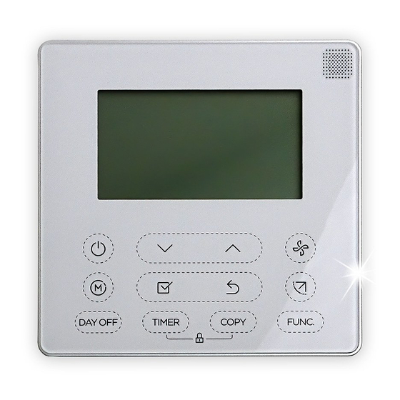
7. Name of button on the wired controller 1 POWER button 6 TIMER button 2 MODE button 7 FAN SPEED button 3 DAY OFF/DEL button 8 BACK bottom 4 ADJUST button 9 SWING bottom 5 CONFIRM button 10 FUNC. button 11 COPY button... -
Page 16: Preparatory Operation
8. Preparatory operation Set the current day and time Press the Timer button for 2 seconds or more. The timer display will ash. Press the button “ ” or “ ” to set the date. The selected date will ash. The date setting is nished and the time setting is prepared after pressing Timer button or CONFIRM button or there is no pressing button in 10 seconds. -
Page 17: Operation
9. Operation Time scale selection Press the buttons “ ” and “ ” for 2 seconds will alternatethe clock tieme display between the 12h&24h scale. To start/stop operation Press the Power button. To set the operation mode Operation mode setting Press the Mode button to set the operation mode.(Heat function is invalid for cool only type unit) - Page 18 9. Operation Room temperature setting Press the button“ ”or “ ” to set the room temperature. Indoor Setting Temperature Range : 17~30°C(62~86°F ). °C & °F scale selection(on some models) Press the buttons “ ” and “ ” for 3 seconds Lower Raise will alternate the temperature display between...
- Page 19 9. Operation Child lock function Press the buttons “ ” and “ ” for 3 seconds to activate the child lock function and lock all buttons on the wire controller. Press the buttons again for 3 seconds to deactivate the child lock function. When the child lock function is activated,the mark appears.
- Page 20 9. Operation Swing function(For the unit without left & right auto swing function models) Up-Down air ow direction and swing Use Swing button to adjust the Up-down air ow direction. 1.Press the button every time, the louver swings 6 degrees. 2.Press and hold the button for 2 seconds,it turns into up-down swing mode,press ti again to stop.
- Page 21 9. Operation 2.Pressing the button “ ” or“ ” can select the movement of four louvers.Each time you push the button,the wire controller select in a sequence that goes from:(the icon means the four louvers move at the same time.) 3.
- Page 22 9. Operation Turbo function (on some models) Under COOL/HEAT mode ,press the FUNC. button to activate the turbo function. Press the button again to deactivate the turbo function. When the turbo function is activated,the mark appears. Follow me function indication Press the FUNC.
-
Page 23: Timer Functions
10. Timer functions WEEKLY timer Use this timer function to set operating times for each day of the week. On timer Use this timer function to start air conditioner operation. The timer operatesand air conditioner operation starts after the time has passed. O timer Use this timer function to stop air conditioner operation. - Page 24 10. Timer functions To set the On or Off TIMER Press the Timer button to select the No display Press the Con rm button and the Timer display is ashing. ex.O timer set at 18:00 Press the button “ ” or “ ”...
- Page 25 10. Timer functions To set the On and Off TIMER Press the Timer button to select the Press the Con rm button and the Clock display is ashing. Press the button “ ” or “ ” to set the time of On timer,and then press the Con rm button to con rm the setting.
-
Page 26: Weekly Timer 1
11. Weekly Timer 1 Weekly timer setting Press the Timer button to select the and then press the Con rm button to con rm. Day of the week setting Press the button “ ” or “ ” to select the day of the week and then press the Con rm button to con rm the setting. - Page 27 11. Weekly Timer 1 ex.Tuesday time scale 1 Up to 4 timer settings can be saved for each day of the week.It is conventent if the WEEKLY TIMER is set according to the user’s life style. Off timer setting of timer setting 1 Press the button “...
- Page 28 11. Weekly Timer 1 WEEKLY timer operation To activate WEEKLY TIMER operation Press the Timer button while is displayed on the LCD. To deactivate WEEKLY TIMER operation Press the Timer button while is disappear from the LCD. To turn off the air conditioner during the weekly timer 1.
- Page 29 11. Weekly Timer 1 To set the DAY OFF (for a holiday) During the weekly timer, press the Con rm button. Press the button “ ” or “ ” to select the day in this week . Press the Day o button to set the DAY OFF. mark is hidden ex.The DAY OFF is set for Wednesday The DAY OFF can be setted for other days by...
- Page 30 11. Weekly Timer 1 DELAY function During the weekly timer, pressing the Del button once, display " ". Press this button twice, display " " and wait 3 seconds to con rm. It means the unit will override 1 hours; Press this button three times,display " "...
- Page 31 11. Weekly Timer 1 Press the Copy button,the letter “CY” will be shown on the LCD. Press the button “ ” or “ ” to select the day to copy to. Press the Copy button to con rm . mark ashes quickly ex.
-
Page 32: Weekly Timer 2
12. Weekly Timer 2 Weekly timer setting Press Timer to select the and press Con rm. Day of the week setting Press “ ” or “ ” to select the day of the week and then press CONFIRM. ON timer setting of timer setting 1 Press “... - Page 33 12. Weekly Timer 2 IMPORTANT: Up to 8 scheduled events can be set on one day. Various events can be scheduled in either MODE, TEMPERATURE ex.Tuesday time scale 1 and FAN speeds. Time setting Press “ ” or “ ” to set the time then press CONFIRM.
- Page 34 12. Weekly Timer 2 Fan speed setting Press “ ” or “ ” to set the fan speed then press CONFIRM. NOTE: This setting is unavailable in the AUTO, DRY or OFF modes. Different scheduled events can be set by repeating steps 3 through 7.
- Page 35 12. Weekly Timer 2 WEEKLY timer operation Press Timer to select the , and then the To start timer starts automatically. To cancel Press the Power buttons for 2 seconds to cancel the timer mode. The timer mode can also be canceled by changing the timer mode using Timer.
- Page 36 12. Weekly Timer 2 Press DAY OFF to create an o day. mark is hidden ex.The DAY OFF is set for Wednesday Set the DAY OFF for other days by repeating the steps 2 and 3. Press BACK to revert to the weekly timer. To cancel, follow the same procedures used for setup.
- Page 37 12. Weekly Timer 2 Press “ ” or “ ” to select the day to copy from. Press COPY, the letters CY appear on the LCD. Press “ ” or “ ” to select the day to copy to. Press COPY to con rm. mark ashes quickly ex.
- Page 38 12. Weekly Timer 2 Delete the time scale in one day. During the weekly timer setting, press CONFIRM. Press “ ” or “ ” to select the day of the week and then press CONFIRM. Press “ ” or “ ”...
-
Page 39: Fault Alarm Handing
13. Fault alarm handing If the system does not properly operate except the above mentioned cases or the above mentioned malfunctions is evident, investigate the system according to the following procedures. D ISPLAY MALFU N C T ION & PROT EC T ION D EFIN E D IGITAL TU BE Error of communication between wire controler and indoor unit... -
Page 40: Queries And Settings
15.Queries and settings When the air conditioning unit is switch machine, Long press “COPY” for 3 seconds to enter a query indoor unit Tn(T1~T4) temperature and fan fault(CF), press“ ”or “ ”to select. Not operating keys 15 seconds or press “Back” or press “ON/OFF”drop out of query temperature. - Page 41 15.Queries and settings Follow me function temperature compensation When the air conditioning unit is o , into the query function of temperature, press“ ”or “ ”to select tF. The compensation temperature Range : -5°C~5°C. Press “Con rm” into setting state, press“ ”or “...
- Page 42 15.Queries and settings Set the highest and lowest temperature values When the air conditioning unit is o , into the query function of temperature, press“ ”or “ ”to select tHI or tLo. Press “Con rm” into setting state, press“ ” or “...
- Page 43 15.Queries and settings Restore factory Settings When the air conditioning unit is o , into the query function of temperature, press“ ”or “ ”to select INIt, the temperature zone displayed --. Press “Con rm” into setting state, press“ ”or “ ”to select to "ON"...
- Page 44 The design and speci cations are subject to change without prior notice for product improvement.Consult with the sales agency or manufacturer for details.