Table of Contents
Advertisement
Quick Links
Technical Manual
Of
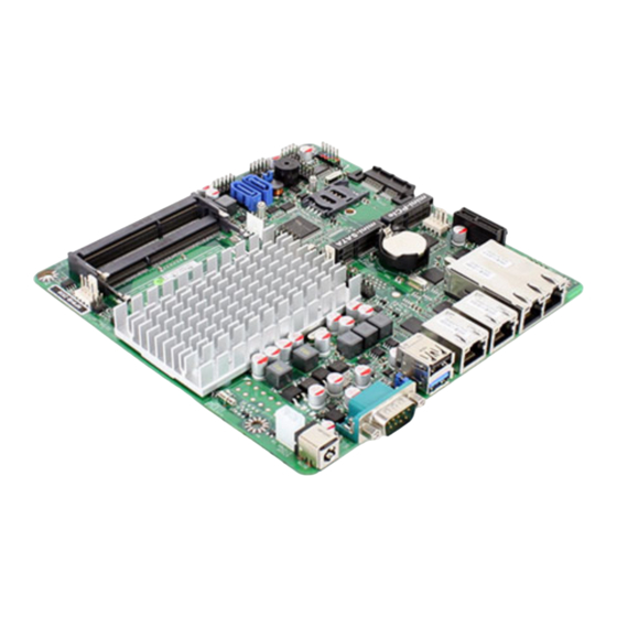
Intel Bay Trail Series CPU
Based Mini-ITX M/B
NO.G03-NF9HB-F
Revision: 2.0
Release date: October 1, 2019
Trademark:
* Specifications and Information contained in this documentation are furnished for information use only, and are
subject to change at any time without notice, and should not be construed as a commitment by manufacturer.
Advertisement
Table of Contents

Related Manuals for JETWAY NF9HB Series


Summary of Contents for JETWAY NF9HB Series
- Page 1 Technical Manual Intel Bay Trail Series CPU Based Mini-ITX M/B NO.G03-NF9HB-F Revision: 2.0 Release date: October 1, 2019 Trademark: * Specifications and Information contained in this documentation are furnished for information use only, and are subject to change at any time without notice, and should not be construed as a commitment by manufacturer.
- Page 2 Environmental Protection Announcement Do not dispose this electronic device into the trash while discarding. To minimize pollution and ensure environment protection of mother earth, please recycle.
-
Page 3: Table Of Contents
TABLE OF CONTENT ENVIRONMENTAL SAFETY INSTRUCTION ................iii USER’S NOTICE ........................iv MANUAL REVISION INFORMATION ..................iv ITEM CHECKLIST ........................iv CHAPTER 1 INTRODUCTION OF THE MOTHERBOARD FEATURE OF MOTHERBOARD ................1 SPECIFICATION ......................2 LAYOUT DIAGRAM ....................3 CHAPTER 2 HARDWARE INSTALLATION JUMPER SETTING .....................7 CONNECTORS AND HEADERS ................11 2-2-1 CONNECTORS .....................11 2-2-2... -
Page 4: Environmental Safety Instruction
Environmental Safety Instruction Avoid the dusty, humidity and temperature extremes. Do not place the product in any area where it may become wet. 0 to 60 centigrade is the suitable temperature. (The figure comes from the request of the main chipset) ... -
Page 5: User's Notice
USER’S NOTICE COPYRIGHT OF THIS MANUAL BELONGS TO THE MANUFACTURER. NO PART OF THIS MANUAL, INCLUDING THE PRODUCTS AND SOFTWARE DESCRIBED IN IT MAY BE REPRODUCED, TRANSMITTED OR TRANSLATED INTO ANY LANGUAGE IN ANY FORM OR BY ANY MEANS WITHOUT WRITTEN PERMISSION OF THE MANUFACTURER. -
Page 6: Chapter 1 Introduction Of The Motherboard Feature Of Motherboard
Chapter 1 Introduction of the Motherboard Feature of Motherboard Onboard Intel ® Bay Trail Series Processor, with low power consumption never denies high performance Support 2* DDR3L 1066/1333 MHz SO-DIMM, up to 8GB Support 1*full-size Mini-PCIE connector ... -
Page 7: Specification
Specification Spec Description Design Mini-ITX form factor; PCB size: 17.0x17.0cm Embedded CPU Integrated with Intel® Bay Trail-D/M/I series CPU 2*DDR3LSODIMM Slot for un-buffered dual channel DDR3L Memory Socket 1066/1333 MHz SDRAM, expandable to 8GB in total Dual channel function supported ... -
Page 8: Layout Diagram
1-3 Layout Diagram Rear IO Diagram LAN2 RJ-45 LAN Port LAN1 RJ-45 LAN Port LAN4 RJ-45 LAN Port USB 2.0 Port COM1 Port 12V DC Power-in Jack USB 3.0 Port LAN3 RJ-45 LAN Port Icon Name Function For user to connect compatible power DC12V Power-in adapter to provide power supply for the Connector... - Page 9 Motherboard Internal Diagram Internal 12V Power Connector SYSFAN1 Header 12V DC Power-in Jack Intel CPU COM1 Port *DDR3L SODIMM Slot (SODIMM1/2) USB 2.0 Port CPUFAN Header Over USB 3.0 Port SMBUS Header VGA Header SATA Hard Disk Power- Out Connector Serial Port Header Mini-SATA Port (COM2)
- Page 10 Motherboard Jumper Position JBAT JPCOM1 JPCOM2 AT-COPEN *JP2 (Optional for NF9HB series) Note: This manual serves as a common manual for NF9HB & NF9HG series Their main differences are listed as below: Model JP2(Jumper) Bypass LAN (on LAN3/LAN4) NF9HB Support...
- Page 11 Jumper Jumper Name Description JBAT Pin 1-2: CMOS RAM Clear Function Setting 4-Pin Block Pin 3-4: Clear ME Function Setting AT_COPEN Pin 1-2: ATX Mode & AT Mode Select 4-Pin Block Pin 3-4: Case Open Message Display Function ME Security Measure Function Select 2-Pin Block *JP2(for NF9HB) Bypass LAN Control Setting...
-
Page 12: Chapter 2 Hardware Installation
Chapter 2 Hardware Installation 2-1 Jumper Setting Pin 1 & 2 of JBAT (4-pin): Clear CMOS Setting JBAT (Pin 1&2) → Clear CMOS Pin 1 1-2 Open: Normal(Default); Pin 1 1-2 Close: Clear CMOS(One Touch). Pin 3 & 4 of JBAT (4-pin): Clear ME Function Setting JBAT (Pin 3&4) →... - Page 13 Pin 1 & 2 of AT_COPEN (4-pin): AT Mode Function Select → AT_COPEN(Pin 1&2) AT Mode Select Pin 1 1-2 Open: ATX Mode Selected(Default); Pin 1 1-2 Close: AT Mode Selected. *ATX Mode Selected: Press power button to power on after power input ready; AT Mode Selected: Directly power on as power input ready.
- Page 14 Bypass LAN (Optional for NF9HB series) 2 4 6 2 4 6 1 3 5 1 3 5 2-4 Closed: 3-4 Closed: 4-6 Closed: SW Control; HW Control; Always. *Note: JP2 is only optional for model NF9HB series, which supports Bypass LAN function(LAN3/4).
- Page 15 JPCOM1 (4-pin): COM1 Port Pin9 Function Select JPCOM1 → COM1 Port 2-4 Closed: 3-4 Closed: 4-6 Closed: RI=RS232; RI= +5V; RI= +12V. JPCOM2 (4-pin): COM2 Header Pin9 Function Select JPCOM2 → COM2 Header 2-4 Closed: 3-4 Closed: 4-6 Closed: RI=RS232; RI= +5V;...
-
Page 16: Connectors And Headers
Connectors and Headers 2-2-1 Connectors (1) Rear I/O Connectors LAN2 RJ-45 LAN Port LAN1 RJ-45 LAN Port LAN4 RJ-45 LAN Port USB 2.0 Port COM1 Port 12V DC Power-in Jack USB 3.0 Port LAN3 RJ-45 LAN Port Warning! The board has a DC 12V power connector (DCIN) in I/O back panel and an internal ATX12V (ATX2P) power connector. - Page 17 (3) SATA1/SATA2(7-pin): SATA II Port Connector These connectors are high-speed SATAII ports that support 3 GB/s transfer rate. Pin No. Defnition * Note: SATA2 shares with MSATA(Mini-SATA slot). (4) SATAPW(4-pin): SATA Power Out Connector Pin 1...
-
Page 18: Headers
(5) CPUFAN/SYSFAN1/SYSFAN2 (4-pin): Fan Connectors Pin1 CPUFAN/ SYSFAN1/SYSFAN2 2-2-2 Headers (1) JW-FP (9-pin): Front Panel Header Pin 1... - Page 19 (2) SPK-LED (7-pin): Speaker Header & PWR LED Header Pin 1 (3) FP_USB1/FP_USB2 (9-pin): USB 2.0 Port Header +DATA +DATA -DATA -DATA Pin 1...
- Page 20 (4) COM2 (9-Pin): Serial Port Header SOUT Pin 1 (5) SMBUS (5-Pin): SM BUS Header Pin1...
- Page 21 (6) GPIO_CON (10-pin): GPIO Header Pin 1 (7) PS2KBMS (6-pin): PS/2 Keyboard & Mouse Header Pin1...
- Page 22 (8) LAN_LED (8-pin): LANLED Header Pin 1 (9) FP_VGA (15-pin): VGA Header Pin2 Pin1...
-
Page 23: Chapter 3 Introducing Bios
Chapter 3 Introducing BIOS Notice! The BIOS options in this manual are for reference only. Different configurations may lead to difference in BIOS screen and BIOS screens in manuals are usually the first BIOS version when the board is released and may be different from your purchased motherboard. Users are welcome to download the latest BIOS version form our official website. -
Page 24: Function Keys
Menu Bar General Help Items Current Setting Value Function Keys Menu Items BIOS Menu Screen Function Keys In the above BIOS Setup main menu of, you can see several options. We will explain these options step by step in the following pages of this chapter, but let us first see a short description of the function keys you may use here: ... -
Page 25: Getting Help
[F1]: General help. [F2]: Previous value. [F3]: Optimized defaults. [F4]: Save & Exit. Press <Esc> to quit the BIOS Setup. Getting Help Main Menu The on-line description of the highlighted setup function is displayed at the top right corner the screen. -
Page 26: Main Menu
Main Menu Main menu screen includes some basic system information. Highlight the item and then use the <+> or <-> and numerical keyboard keys to select the value you want in each item. System Date Set the date. Please use [Tab] to switch between data elements. System Time Set the time. -
Page 27: Advanced Menu
3-7 Advanced Menu OS Selection The optional settings: [Android]; [Windows 8.X]; [Windows 7]. *Note: User needs to go to this item to select OS before installing OS. If Windows Embedded standard 8, please select [Windows 8x] and set “USB 3.0 Support”... - Page 28 Press [Enter] to make settings for the following sub-items: Wake-up System with Fixed Time Use this item to enable or disable system wake-up on alarm event. The optional settings: [Disabled]; [Enabled]. When set as [Enabled], system will wake on the hour/min/sec specified. Wake-up System with Dynamic Time Use this item to enable or disable system wake-up on alarm event.
- Page 29 ERP Support The optional settings: [Enabled]; [Disabled]. This item should be set as [Disabled] if you wish to have all active wake-up functions. WatchDog Timer Use this item to enable or disable WatchDog Timer Control. When set as [Enabled], the following sub-items shall appear: WatchDog Timer Value User can set a value in the range of [10] to [255].
- Page 30 CPUFAN / SYSFAN1/ SYSFAN2 Smart Mode When set as [Enabled], the following sub-items shall appear: CPUFAN / SYSFAN1/ SYSFAN2 Full-Speed Temperature Use this item to set CPUFAN/SYSFAN1/SYSFAN2 full speed temperature. Fan will run at full speed when above this temperature. CPUFAN / SYSFAN1/ SYSFAN2 Full-Speed Duty Use this item to set CPUFAN/SYSFAN1/SYSFAN2 full speed duty.
- Page 31 The optional settings are: [VT100]; [VT100+]; [VT-UTF8]; [ANSI]. Bits per second The optional settings are: [9600]; [19200]; [38400]; [57600]; [115200]. Data Bits The optional settings are: [7]; [8]. Parity The optional settings are: [None]; [Even]; [Odd];[Mark]; [Space]. Stop Bits The optional settings are: [1]; [2]. Flow Control The optional settings are: [None];...
- Page 32 compatible settings. Press [Enter] to make settings for the following sub-items. Out-of-Band Mgmt Port The default setting is: [COM1]. Terminal Type The optional settings are: [VT100]; [VT100+]; [VT-UTF8]; [ANSI]. Bits per second The optional settings are: [9600]; [19200]; [57600]; [115200]. Flow Control The optional settings are: [None];...
- Page 33 The optional settings: [Enabled]; [Disabled]. When set as [Enabled], a VMM can utilize the additional hardware capabilities provided by Vanderpool Technology. EIST The optional settings: [Disabled]; [Enabled]. Use this item to enable or disable Intel SpeedStep. CPU C Status Use this item to enable or disable CPU C status. The optional settings: [Disabled];...
- Page 34 When set as [Enabled], the following sub-items shall appear: Ipv4 PXE Support The optional settings are: [Disabled]; [Enabled]. Use this item to enable Ipv4 PXE Boot Support. When set as [Disabled], Ipv4 boot option will not be created. Ipv6 PXE Support The optional settings are: [Disabled];...
- Page 35 This is a workaround for OSes without XHCI hand-off support. The XHCI ownership change should be claimed by XHCI driver. The optional settings are: [Enabled]; [Disabled]. EHCI Hand-off This is a workaround for OSes without EHCI hand-off support. The EHCI ownership change should be claimed by EHCI driver.
-
Page 36: Chipset Menu
3-8 Chipset Menu North Bridge Press [Enter] to make settings for the following sub-items: PAVC Use this item to enable or disable protected audio video control. The optional settings are: [Disabled]; [LITE Mode]; [SERPENT Mode]. DVMT Pre-Allocated Use this item to select DVMT 5.0 pre-allocated (fixed) graphics memory size used by the internal graphics device. - Page 37 *Note: The above three setting items: ‘LAN3&4 Bypass State @ Power On’, ‘LAN3&4 Bypass State @ Power Off’ and ‘LAN3&4 Bypass WDT Function’ are only optional for NF9HB series. NF9HG series do not support these functions so there are no such items in BIOS settings.
-
Page 38: Security Menu
Onboard Lan1 Controller/ Onboard Lan2 Controller Onboard Lan2 Controller Onboard Lan3 Controller The optional settings are: [Enabled]; [Disabled]. System State after Power Failure Use this item to select AC power state when power is re-applied after a power failure. The optional settings are: [Always Off]; [Always On]; [Former State]. * The option [Always On] and [Former State] are affected by ERP function. -
Page 39: Boot Menu
3-10 Boot Menu Boot Configuration Setup Prompt Timeout Use this item to set number of seconds to wait for setup activation key. Bootup Numlock State Use this item to select keyboard numlock state. The optional settings are: [On]; [Off]. Quiet Boot The optional settings are: [Disabled];... -
Page 40: Save & Exit Menu
3-11 Save & Exit Menu Save Changes and Reset This item allows user to reset the system after saving the changes. Discard Changes and Reset This item allows user to reset the system without saving any changes. Restore Defaults Use this item to restore /load default values for all the setup options. Save as User Defaults Use this item to save the changes done so far as user defaults.