Table of Contents
Advertisement
Quick Links
Advertisement
Table of Contents

Summary of Contents for Ward-Beck Systems AMS81
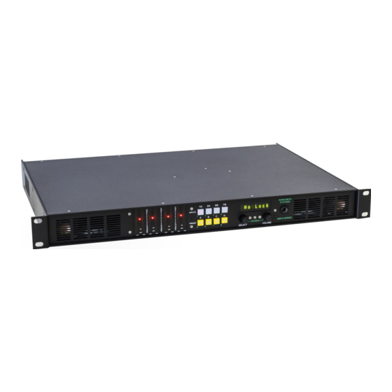
- Page 1 AMS81 8 CHANNEL AUDIO MONITORING SYSTEM by Ward-Beck Systems Rev:Oct.01 2014...
-
Page 2: Front Panel Displays And Controls
AMS81 (version 2.1.1.7 and above) Carefully unpack your AMS81 and make sure that damage has not occurred during shipping. The unit should be ready for use as soon as it is plugged in to the AC power source and a signal is connected to it. -
Page 3: Front Panel Controls
FRONT PANEL CONTROLS There are eight illuminated push button switches arranged in two rows of four. The upper row designated INPUTS selects the input source to be monitored. The lower row designated PRESETS selects a preset configuration or condition under which the signal is monitored. -
Page 4: System Setup
SYSTEM SETUP To enter system setup, press and hold INPUT buttons 1/2 and 7/8 with one hand and press the SELECT knob. The readout will display S ystem . Press the SELECT button again to enter the mode of operation selection. The readout will display Mode X... - Page 5 Rotate the SELECT knob another step clockwise to enter the AES OUTPUT #4 Setup. The readout will display O ut4 a bove the SELECT knob and I n4 or M on above the VOLUME knob. Out4 In4 - means that AES input #4 will be routed to AES output #4. Out4 Mon...
- Page 6 Rotate the SELECT knob another step clockwise. The readout will display O /P above the SELECT knob and either V ar or F ix above the VOLUME knob. Rotating the VOLUME knob in either direction will toggle between V ar and F ix . O/P Var ...
- Page 7 Rotate the SELECT knob one more step clockwise. The readout will display S pkr above the SELECT knob and either O n or O ff above the VOLUME knob. Rotating the VOLUME knob in either direction will toggle between O n and Off. (In Version 1.x.x.x.) Spkr On means the internal speakers and headset jack are enabled, and enables monitor output.
-
Page 8: Checking The Firmware
CHECKING THE FIRMWARE When the system setup mode has been activated and the readout displays System , rotating the SELECT knob clockwise will cycle through the following: Inputs - This configuration setup allows you to select the input sources that will be enable during monitoring. - Page 9 INPUTS SETUP (for all modes) A fully assembled AMS8 has multiple program inputs (75 Ω , 110 Ω , Analog, SDI 1 (A) Groups 1 and 2, SDI 1 (A) Groups 3 and 4 and SD1 2 (B) Groups 1 and 2 and SDI 2 (B) Groups 3 and 4.
- Page 10 ASSIGNMENT SETUP (for Mode 1 only) The AMS8 has the ability to monitor multiple inputs, IN1 to IN4 at 75 Ω , 110 Ω and Analog, as well as, eight digital programs within one of the two SDI streams. The Assigns setup allows an operator to assign any one of these inputs to the four INPUT select pushbutton switches for rapid selection.
- Page 11 CONFIGURING A PRESET (Presets can only be configured when operating in MODE 2) Press and hold a PRESETS button for approximately three seconds. If preset button A is selected, the readout should display A L1 above the SELECT knob and either O ff or a level between - 15 and + 15 above the VOLUME knob. Rotating the SELECT knob in either direction cycles through the eight available sources that are displayed on the LED meters.
- Page 12 OPERATING IN MODE 1 (Default for units with Dolby Decoder installed) The AMS8 would be set to operate in Mode 1 when dealing with multiple channels PCM or Dolby digital signals. A Dolby decoder must be installed in the unit. Input sources can be either PCM, Dolby AC-3 or Dolby E.
- Page 13 display M ute. The two channel PCM signal may also be converted to a ProLogic Surround version by rotating the SELECT knob in either direction. The readout will display PCM /PL . The ProLogic signal comprises Left, Right, Centre, Left rear and Right rear. These signal levels are displayed on the CH1, CH2, CH3, CH5 and CH6 LED bar graphs respectively.
- Page 14 If the signal is lost through interruption or if an internal error occurs and the unit cannot lock to the incoming signal, the readout will indicate N o Lock. The four PRESETS pushbuttons may be used to listen to the signals solo, discretely or summed (for phase checking).
- Page 15 OPERATING IN MODE 2 In Mode 2, the AMS8 operates as a multi-channel monitor box with the ability to proportionally mix any of the inputs to the left and right monitor channels. All inputs must be PCM. The unit will accept eight inputs; four unbalanced and four balanced sources.
- Page 16 Select SDI 1/2 for SDI 1 (A) Groups 1 and 2 Select SDI 3/4 for SDI 1 (A) Groups 3 and 4 Select SDI 5/6 for SDI 2 (B) Groups 1 and 2 Select SDI 7/8 for SDI 2 (B) Groups 3 and 4...
- Page 17 OPERATING IN MODE 4 The AMS8 would be set to operate in Mode 4 for a task specific application. In Mode 4, the types of signals that can be connected to the input source connectors are strictly defined. Inputs 1, 2 and 3 must be PCM and input 4 must be a multi-channel Dolby signal.
-
Page 18: The Volume Control
The frame rate ( F r ) is available on Dolby E signals only, e.g. F r 29.97. L astly is the Data Rate ( D r ) which is only available on Dolby AC-3 signals. For other signals, the readout will display ... - Page 19 AMS8 CONNECTER LAYOUTS...
- Page 20 AMS8-1 FUNCTIONAL DIAGRAM...
-
Page 21: Data Table
DATA TABLE D OLBY DIGITAL CONFIGURATION (DD) FORMAT - NO LOCK - 1+1 - PCM - 1/0 - DOLBY DIGITAL AC-3 (DD) - 2/0 - DOLBY E (E) - 3/0 - 2/1 AUDIO SOURCE TYPE - 3/1 - ANALOG - 2/2 - AES 75 (UNBALANCED) - 3/2... - Page 22 D OLBY SURROUND INFORMATION (DS) FRAME RATE (FR) - Dsrd (Dolby Surround) - 23.98 fps - NtDs (Not Dolby Surround) - 24.00 - NtId (Not Indicated) - 25.00 - 29.97 DOLBY CENTERMIX (C) - 30.00 - 50.00 - -3.0 dB - 59.94 - -4.5 dB - 60.00...
-
Page 23: Specifications
23.5 dBu Noise less than -70 dbfs Less than 0.05% Connector Type 3 pin Terminal Block HEADSET JACK Type ¼ inch TRS jack POWER Input 90-230 VAC,50-60 Hz Ward-Beck Systems Inc. reserves the right to change performance specifications without prior notice. -
Page 24: Warranty
Ward-Beck Systems Inc. will repair or replace, at its option and without charge, all said products or parts thereof which upon factory inspection prove to be defective during the warranty period, provided that: The original serial numbers are intact and have not been tampered with. - Page 25 Website: www.ward - beck.com E-Mail: sales@ward - beck.com...