Table of Contents
Advertisement
Quick Links
Advertisement
Table of Contents

Related Manuals for Fujitsu DSL Modem

Summary of Contents for Fujitsu DSL Modem
- Page 3 DSL Modem Installation Guide, Issue 2 September 1998 FJTU-320-600-900 Copyright Notice The contents of this document are subject to change without notice. Neither this document, nor any portion thereof, is to be reproduced in any form without written permission of FNC. Information contained in this document is FNC Propriety and Confidential and is for use by FNC authorized...
- Page 5 Safety Information Safety Warnings Potentially hazardous voltages exist within this unit. Always observe standard safety precautions during installation, operation, and maintenance of this product. There are no user provisionable options. FCC Warning This equipment has been tested and found to comply with the limits for a Class B digital device, pursuant to Part 15 of the FCC Rules.
-
Page 7: Table Of Contents
DSL Modem Package Contents ... 3 2 Installing the DSL Modem Mounting the DSL Modem ....4 DSL Modem Front Panel Description ..5 DSL Modem Rear Panel Description . -
Page 9: Introduction
Introduction Congratulations on your purchase of a Digital Subscriber Line (DSL) modem. The DSL Modem is part of a system that provides an integrated end-to-end solution for data connectivity, multimedia services, and high-speed Internet access services using an asymmetrical digital subscriber line (ADSL) transmission over your current telephone wiring. -
Page 10: Unpacking Instructions
The DSL Modem splitter is completely passive, providing “lifeline” or continuous, telephone service even if the power fails. The DSL Modem encodes the data sent from your PC to a corresponding DSL Modem, located at your local telephone company. -
Page 11: Dsl Modem Package Contents
1.3 DSL Modem Package Contents The DSL Modem package contains: • DSL Modem • Ethernet (or null) crossover cable • ASDL cable (straight) • Power supply convertor Part # FC9660CB23 Part # FC9660RA12 DSL Modem Ethernet Crossover Cable Part # FC9660CB22... -
Page 12: Installing The Dsl Modem
Installing the DSL Modem 2.1 Mounting the DSL Modem The DSL Modem can be installed on desktops, shelves or mounted on walls. The wall mounting requires two wall anchors (not included). The feet located on the bottom of the modem are used to hang the unit on the wall anchors. -
Page 13: Dsl Modem Front Panel Description
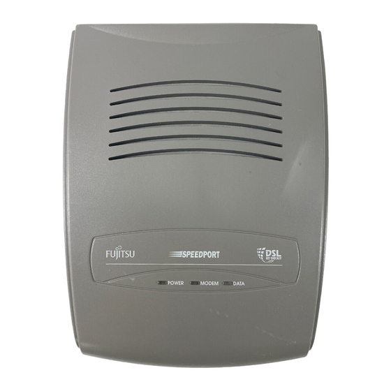
2.2 DSL Modem Front Panel Description Figure 2-2 depicts the DSL Modem. Figure 2-2: DSL Modem The following table describes the lights on the front panel of the DSL Modem. Modem Lights Description POWER Indicates if power is applied to the modem. -
Page 14: Dsl Modem Rear Panel Description
2.3 DSL Modem Rear Panel Description Figure 2-3 depicts the rear panel of the DSL Modem. DATA LINE DATA LINE Figure 2-3: DSL Modem Rear Panel The following table describes the functions of the items located on the rear panel. -
Page 15: Connecting The Dsl Modem To The Splitter
(NID) to separate the voice and data interior wire paths. Before connecting the wires from the NID to the DSL Modem, verify that the inside wire pair serving the DSL Modem has an isolated path from the NID to the modem. Do not connect a telephone to the same wire pair. -
Page 16: Inside Wiring Procedures
3.2 Inside Wiring Procedures WARNING: Interior home wire is the homeowner responsibility. The following wiring diagrams represent a standard wiring scheme. Not all homes will follow this convention. Standard telephone company inside wire coverage options will not cover the cost to repair voice path problems that may arise as a result of homeowner wiring attempts. - Page 17 Note: ISDN Users–If you previously had ISDN, you can use the existing ISDN wired RJ-45 jack. 2. If you are using spare inside wire pair for the DSL Modem (data), install a new RJ-11/RJ-45 wall plate. 3. Connect the wires attached to the green and red screws on the NID to the green and red pins on the wall jack.
- Page 18 RJ-11 and RJ-45 Jacks RJ-11 Cable RJ-45 Connector ADSL Cable (Straight)* Telephone Company RJ-11 Connector DSL Modem* DATA DATA LINE LINE Ethernet Crossover Cable* *Asterisk denotes item included in the DSL modem package. Figure 3-2: Spare Inside Wire Interconnection...
- Page 19 Connect the RJ-11 end of the ADSL cable (straight) to the LINE connector on the modem. The LINE connection is located on the back panel of the DSL Modem. The ADSL cable (straight) is included in the DSL Modem package.
- Page 20 Note: The ethernet cable provided is a crossed cable and must be used when connecting the DSL Modem directly to the network interface card in the computer. A diagram for using new wire is shown in Figure 3-3. The numbers circled in the diagram correlate to the steps in the procedure.
-
Page 21: Multiple Pcs Wiring Procedure
(SOHO), or small business customer using the ADSL to achieve high- speed access to the Internet. A multiport Ethernet hub is connected to the DSL Modem. The hub allows multiple PCs to share bandwidth to and from the DSL Modem. The Ethernet cable (straight) shown in Figure 3-4 is not included in the DSL Modem package. -
Page 22: Turn Up And Operation
4.1 Connecting the Power Supply Convertor The protective ground connection to the DSL Modem must always be made via the power supply convertor. To turn on the DSL Modem, insert the power supply convertor into the Power connection and then plug the power supply into a powered 120 vac wall outlet. The Power connection is located on the back panel of the DSL Modem. - Page 23 Figure 4-1 lists the light definitions for turn-up. The modem should initialize in the sequence described in flow chart. DSL Modem Turn-up Flow Chart Modem is powered on. For a few seconds, the modem is performing several self-tests. POWER MODEM DATA Modem is idle.
- Page 24 BACK COVER/BLANK PAGE...