
Related Manuals for Bard BrightStat 8403-081


Summary of Contents for Bard BrightStat 8403-081
- Page 1 INSTALLATION AND APPLICATION INSTRUCTIONS BrightStat Air Conditioner/Heat Pump Room Controller Bard Manufacturing Company, Inc. Manual: 2100-680 Bryan, Ohio 43506 Supersedes: www.bardhvac.com Date: 8-29-18 Page 1 of 18...
-
Page 2: Table Of Contents
CONTENTS Dimensions ............3 Specifications ............ 3 Overview ............4 Installation............6 Remote Sensor Accessories ......... 7 Home Screen Display .......... 8 How to Enter Setup Screen ........9 Power Outage Clock Reset ......... 10 Passive Infrared Sensor ........11 Optional Network Setup ........ -
Page 3: Dimensions
Manual 2100-680 Page 3 of 18... -
Page 4: Overview
HVAC implementation. standard implementations necessary for HVAC systems. BrightStat Controller Models Bard Part Number Description Part Number Found on Back of Controller 8403-081 With Humidity and Motion Sensors... - Page 5 NOTE: RC (5) and RH (7) must both be powered for Terminal Designation Function heating and cooling operation. ON/OFF VENT OUTPUT PER BO 1 SCHEDULE BO 2 Y2 COMP OUTPUT BO 3 Y1 COMP OUTPUT BO 4 G OUTPUT COOL 24VAC IN 1 2 3 4 5 6 7 8 9 10 11 12 24VAC COM...
-
Page 6: Installation
INSTALLATION Location FIGURE 2 Install Base • Do not install on outside wall. • Do not install in areas with direct heat source. • Do not install near any air discharge grill. • Do not install in areas exposed to direct sunlight. •... -
Page 7: Remote Sensor Accessories
REMOTE SENSOR ACCESSORIES TABLE 2 Remote Sensor Accessories Model Number Description 8612-058 Wall-Mounted Temperature Sensor Wall-Mounted Temperature Sensor with Override Button 8612-059 and Occupancy Status LED NOTE: If one or multiple sensor(s) is/are connected TABLE 3 into the RS terminal, the internal temperature Temperature vs. -
Page 8: Home Screen Display
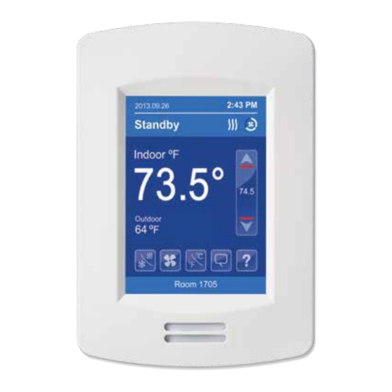
HOME SCREEN DISPLAY Typical Hospitality User Interface Shown Time Date System Status Occupancy Status Fan Status Up Arrow Increase Temperature Setpoint Indoor Temperature Actual Setpoint Down Arrow Outdoor Temperature Decrease Temperature Setpoint System Mode Help Short Network Message Fan Mode Language Selection Temperature Units Custom Display Message... -
Page 9: How To Enter Setup Screen
HOW TO ENTER SET-UP SCREEN Touch and hold this point for 3 seconds to enter set-up mode. NOTE: If a configuration/installer password is activated to prevent unauthorized access to the configuration menu parameters, a password entry prompt shows to prevent access to device configuration components. -
Page 10: Power Outage Clock Reset
POWER OUTAGE CLOCK RESET In the event of a power outage, BrightStat Room Controllers will retain the correct time as long as the duration of the power outage is not prolonged. Depending on the duration of the power outage, the room controller's internal clock may need to be updated or reset completely. -
Page 11: Passive Infrared Sensor
PASSIVE INFRARED SENSOR Initially, the room controller is in Stand-by mode and While in Stand-By or Unoccupied mode, any motion Stand-by setpoints are used. When the Passive Infra- switches the room back to Occupied mode. Red (PIR) sensor detects motion, the Occupancy The PIR sensor is located near the bottom of the front status switches to Occupied and the Stand-By Time of the BrightStat controller. - Page 12 Energy Savings Typical Savings of 10-30% PIR can maximize energy saving from 10-30% by adjusting temperature setpoints in unoccupied zones during scheduled periods. Time of Day (EST) Typical Consumption PIR Thermostat Consumption Savings Manual 2100-680 Page 12 of 18...
- Page 13 Deployment The examination room shows one room controller installed adjacent to the door. In this area of the room, Placement of the room controller must be given occupant traffic is high and ensures the occupant will consideration. It is recommended to install the room almost always cross the PIR detection path laterally controller as close to a door as possible (but not so and within the detection range.
- Page 14 Example of Non-Recommended Deployment The waiting room shows one room controller installed in the corner of the room, and a second room controller The illustration below shows four room controllers (two installed beside the reception area. For the room for each room) installed in non-ideal locations for the controller installed in the corner, the opening/closing of two rooms.
-
Page 15: Optional Network Setup
OPTIONAL NETWORK SET-UP Wireless Communication BACnet Communication Wiring ® BACnet thermostat BACnet thermostat BACnet thermostat Notes: - Wiring should be daisy chained No communication wires required - Respect polarity - If using 2 conductor shielded wires, connect the shield of each feed together on the back of the controller. -
Page 16: Controllers' Occupancy Sequence
CONTROLLERS' OCCUPANCY SEQUENCE OF OPERATION SCHEMATIC Setpoints 26.5°C 80°F Unoccupied cool 24.5°C 76°F Stand-by cool 22°C 22°C Deadband 72°F Deadband 72°F Occupied cool Deadband Occupied heat 70°F 70°F 21°C 21°C Stand-by heat Stand-by 66°F time 19°C Unoccupied Unoccupied heat time 62°F 16.5°C Time... -
Page 17: Sed Series Wireless Sensors
SED SERIES WIRELESS SENSORS Wireless ZigBee Pro Motion Sensors BrightStat controllers with ZigBee Pro wireless sensors can be used in stand-alone mode, or with integration to a central management system, to allow for advanced functions such as central reservation and occupancy functions. - Page 18 SED-CMS SED-WDS SED-WMS Hidden Hidden switch switch Hidden switch Manual 2100-680 Page 18 of 18...