Table of Contents
Advertisement
Quick Links
INSTALLATION INSTRUCTIONS
EARTH-FRIENDLY R-410A REFRIGERANT:
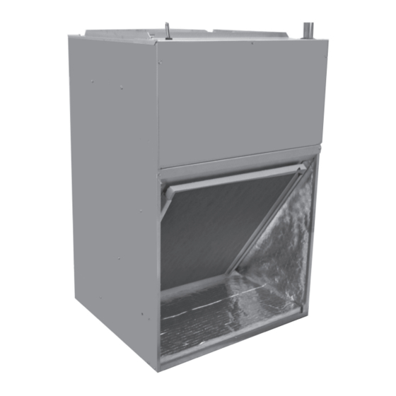
(-)F1T High Efficiency w/Aluminum Coil
(-)F1P Standard Efficiency w/Aluminum Coil
WARNING
WARNING
!
!
These instructions are intended as an aid to qualified licensed
These instructions are intended as an aid to qualified licensed
service personnel for proper installation, adjustment and
service personnel for proper installation, adjustment and
operation of this unit. Read these instructions thoroughly before
operation of this unit. Read these instructions thoroughly before
attempting installation or operation. Failure to follow these
attempting installation or operation. Failure to follow these
instructions may result in improper installation, adjustment,
instructions may result in improper installation, adjustment,
service or maintenance possibly resulting in fire, electrical
service or maintenance possibly resulting in fire, electrical
shock, property damage, personal injury or death.
shock, property damage, personal injury or death.
FRONT RETURN AIR HANDLERS
ACCREDITED
ISO 9001:2008
92-20521-99-06
SUPERSEDES 92-20521-99-05
Advertisement
Table of Contents

Related Manuals for Fujitsu F1T Series


Summary of Contents for Fujitsu F1T Series
- Page 1 INSTALLATION INSTRUCTIONS FRONT RETURN AIR HANDLERS EARTH-FRIENDLY R-410A REFRIGERANT: (-)F1T High Efficiency w/Aluminum Coil (-)F1P Standard Efficiency w/Aluminum Coil WARNING WARNING These instructions are intended as an aid to qualified licensed These instructions are intended as an aid to qualified licensed service personnel for proper installation, adjustment and service personnel for proper installation, adjustment and operation of this unit.
-
Page 2: Table Of Contents
TABLE OF CONTENTS 1.0 SAFETY INFORMATION ................3 2.0 GENERAL INFORMATION ................5 2.1 Important Information About Efficiency & Indoor Air-Quality ....5 2.2 Checking Product Received ..............5 2.3 Model Number Nomenclature ............... 6 2.4 Available Models ..................6 2.5 Dimensions & Weights ................7 2.6 Importance of Proper Indoor/Outdoor Match-Ups ........ 8 2.7 Importance of a Quality Installation ............8 3.0 INSTALLATION ..................8 3.1 Tools & Refrigerant ................. 8 3.1.1 Tools Required for Installing & Servicing R-410A Models ... 8 3.1.2 Specifications of R-410A .............. 8 3.1.3 Quick Reference Guide for R-410A ..........9 3.2 Applications .................... 9 3.2.1 Mounting Options ............... 9 3.2.1.1 Wall Mount . -
Page 3: Safety Information
5.0 COMPONENTS & CONTROLS ..............27 5.1 Blower Motor ..................27 5.2 Motor Run Capacitor ................27 5.3 Blower Control ..................27 5.4 Blower ....................28 5.5 Transformer ..................28 5.6 Indoor Coil .................... 28 6.0 ACCESSORIES & KITS ................29 6.1 Electric Resistance Heater Kits .............. 29 6.2 Drain Pan Overflow Switch Kit .............. 29 6.3 Bottom Return Conversion Kit .............. 30 6.4 Louvered Cabinet Grille ................ 30 6.5 Decorative Wall Grille ................31 7.0 MAINTENANCE ..................32 7.1 Air-Filter . - Page 4 WARNING WARNING (SEE SECTION 3.12.2: GROUNDING) PROPOSITION 65: This appliance The unit must be permanently grounded. Failure to do so can result in electri- contains fiberglass insulation. cal shock causing personal injury or death. Respirable particles of fiberglass are known to the State of California WARNING to cause cancer.
-
Page 5: General Information
2.0 GENERAL INFORMATION 2.1 IMPORTANT INFORMATION ABOUT EFFICIENCY AND INDOOR AIR QUALITY Central cooling and heating equipment is only as efficient as the duct system that carries the cooled or heated air. To maintain efficiency, comfort and good indoor air quality, it is important to have the proper balance between the air being supplied to each room and the air returning to the cooling and heating equipment. -
Page 6: Model Number Nomenclature
2.3 MODEL NUMBER EXPLANATION FIGURE 2 MODEL NUMBER EXPLANATION (-) F 1 P 24 21 S P A N J A N 00 *** OPTION CODE BLANK = NONE FACTORY HEAT 00 = NO HEAT 08 = 8 kW 03 = 3kW 10 = 10 kW 05 = 5 kW DISCONNECT... -
Page 7: Dimensions & Weights
2.5 DIMENSIONS & WEIGHTS NOTE: 24” CLEARANCE REQUIRED FIGURE 3 IN FRONT OF UNIT FOR FILTER DIMENSIONS AND WEIGHTS AND COIL MAINTENANCE. HIGH VOLTAGE CONNECTION, 1-3/8” AND 7/8” KNOCKOUTS FLANGES FOR FIELD INSTALLED DUCTWORK LIQUID LINE CONNECTION COPPER (SWEAT) VAPOR LINE CONNECTION COPPER (SWEAT) FRONT RETURN SHOWN. -
Page 8: Importance Of Proper Indoor/Outdoor Match-Ups
2.6 IMPORTANCE OF PROPER INDOOR/OUTDOOR MATCH-UPS To assure many years of reliable operation and optimum customer comfort and to assure the outdoor unit warranty remains valid, an air-handler model should be selected that is properly matched to the outdoor unit. This is especially critical for heat pump systems to assure proper refrigerant charge balance between the cooling and heating modes. -
Page 9: Quick Reference Guide For R-410A
Pressure: The pressure of R-410A is approximately 60% (1.6 times) greater than R-22. Recovery and recycle equipment, pumps, hoses, and the like must have design pressure ratings appropriate for R-410A. Manifold sets need to range up to 800 psig high-side and 250 psig low-side with a 550 psig low-side retard. Hoses need to have a service pressure rating of 800 psig. -
Page 10: Front Return Air
FIGURE 4 DIMENSIONS FOR DUCTWORK & DRAINS 3.2.1.3 FRONT RETURN AIR Most applications for this style of air-handler bring the return air through into the front of the unit from the conditioned space with no return duct. The unit is shipped from the factory to accommodate this type of installation with no modifications. -
Page 11: Installation In Corrosive Environments
FIGURE 5 WALL MOUNT • No perimeter supply flanges are provided. If a full perimeter supply duct is used, it is the responsibility of the installer to provide duct flanges as needed, to secure and seal the supply duct to prevent air leakage and the sweating that will result. •... -
Page 12: Auxiliary Overflow Pan
FIGURE 6 FRAME MOUNT 3.3 AUXILIARY OVERFLOW PAN To comply with building codes, an auxiliary overflow pan must installed under all equip- ment containing evaporator coils that are located in any area of a structure where dam- age to the building or building contents may occur as a result of an overflow of the coil drainpan or a stoppage in the primary condensate drain piping. -
Page 13: Ductwork
3.6 DUCTWORK Field ductwork must comply with the National Fire Protection Association NFPA 90A, NFPA 90B and any applicable local ordinance. WARNING Do not, under any circumstances, connect return ductwork to any other heat producing device such as fireplace insert, stove, etc. Unauthorized use of such devices may result in fire, carbon monoxide poisoning, explo- sion, personal injury or property damage. -
Page 14: Orifice Size: (-)F1P*****P Models
3.8 ORIFICE SIZE: (-)F1P*****P MODELS (-)F1P*****P air-handlers are equipped with a fixed orifice (piston) sized for a typical 13 SEER R-410A outdoor unit. The piston must be changed if the outdoor unit has a higher or lower efficiency or if the system is using R-22 as a refrigerant. The chart below shows recommended orifice sizes for various efficiencies for R-410A and R-22. -
Page 15: Leak Testing
Protect the TXV, copper to aluminum suction header joint, and outdoor unit service valves from overheating using a wet rag or heat sink compound. Leave the wet rag or heat sink material in place until the joint and surrounding tubing cools down to a safe temperature. -
Page 16: Thermostat
FIGURE 7 CONDENSATE DRAIN TRAP ST-A1244-01-01 • The auxiliary drain line should be run to a place where it will be noticeable if it becomes operational. The building occupant should be warned that a problem exists if water should begin running from the auxiliary drain line. An auxiliary drain shut-off switch can be installed in lieu of an auxiliary drain line. -
Page 17: Grounding
The PSC indoor blower motor in the (-)F1P air-handlers must also be configured for 208 volt applications to assure full air-flow delivery at the reduced voltage. This step is not required on (-)F1T air-handlers since they have constant torque ECM motors. To con- figure the PSC motor in (-)F1P air-handlers for 208 volt applications, unplug the PURPLE motor lead connected to the insulated terminal on the end of the ORANGE wire coming from the transformer. -
Page 18: Electrical Data - Blower Motor Only - Without Electric Heat
3.12.5 ELECTRICAL DATA – BLOWER MOTOR ONLY – WITHOUT ELECTRIC HEAT MINIMUM MAXIMUM CIRCUIT MODEL VOLTAGE PHASE HERTZ SPEEDS CIRCUIT CIRCUIT AMPS AMPACITY PROTECTION (-)F1P18 208/230 1075 (-)F1P24 208/230 1075 (-)F1P30 208/230 1075 (-)F1P36 208/230 1075 (-)F1T24 208/230 300-1100 (-)F1T36 208/230 300-1100 *Blower motors are all single phase motors. -
Page 19: Electric Heater Kit Supplemental Information
3.12.7 ELECTRIC HEATER SUPPLEMENTAL INFORMATION MFG DATE/ RHEEM SALES COMPANY, INC. ASSEMBLED IN THE U.S.A. 12/2009 FRQ: AREUNI AUX STATS–UNES Contractor RF1P2421STAN00 F000900001 MODEL/MODELE# SERIAL/EN SERIES # should “mark VOLTS 208/240 PH/HZ 1 / 60 MOTOR HP/F.L.A. MOTEUR PSC/F.L.A. or check” the ATTENTION: MARK HEATER KIT INSTALLED IN LEFT COLUMN/LA TROUSSE D’APPAREIL DE CHAFFAGE DE MARQUE A INSTALLE DANS LA COLONNE GAUCH´E... -
Page 20: Control Wiring
3.12.8 CONTROL WIRING IMPORTANT: Class 2 low voltage control wire should not be run in conduit with power wiring and must be separated from power wiring, unless class 1 wire of proper voltage rating is used. • Low voltage control wiring should be 18 Awg. color-coded. For lengths longer than 100 ft., 16 Awg. -
Page 21: Selecting Indoor Blower Motor Speed
3.13.2 SELECTING INDOOR BLOWER MOTOR SPEED The (-)F1P and (-)F1T air-handlers must be configured in the field to assure proper air- flow is delivered for the particular application it is being used in. Refer to the AIR-FLOW PERFORMANCE DATA in Section 3.13.3 to determine which speed tap is appropriate for the application. -
Page 22: Air-Flow Performance Data
3.13.3 AIR-FLOW PERFORMANCE DATA 3.13.3.1 (-)F1P (PSC MOTOR) Manufacturer Model/ Motor Blower Size/ CFM Dry Delivery/filter/heaters/RPM/Watts Recommended Nominal Speed Motor Motor HP # External Static Pressure-Inches W.C. Cooling From Speed Air-Flow Range of Speeds Capacity Factory (Max/Min) CFM 0.10 0.20 0.30 0.40 0.50... -
Page 23: F1T (Constant Torque Ecm Motor)
3.13.3 AIR-FLOW PERFORMANCE DATA (continued) 3.13.3.2 (-)F1T (CONSTANT TORQUE ECM MOTOR) X-13 Manufacturer Model/ Motor Blower Size/ CFM Dry Delivery/filter/heaters/RPM/Watts Recommended Nominal Speed Motor Motor HP # External Static Pressure-Inches W.C. Cooling From Speed Air-Flow Range of Speeds Capacity Factory (Max/Min) CFM 0.10 0.20... -
Page 24: Start-Up
4.0 START-UP 4.1 PRE-START CHECKLIST PRE-START CHECKLIST Is unit properly located, level, secure and service- able? Has auxiliary pan been provided under the unit with separate drain? (Units installed above a finished ceiling). Is condensate line properly sized, run, trapped, pitched and tested? Is ductwork correctly sized, run, taped and insu- lated? -
Page 25: Heat Pump Heating Mode
13kW heater kits and higher, a 2-stage heat thermostat can be used to energize the W2 terminal on the blower control board upon a call for a 2nd stage of heat which will in turn will energize the 2nd stage heater elements. The heater kit will cycle between the 1st and 2nd stages of heat at the direction of the thermostat. -
Page 26: Checking Indoor Air-Flow
4.6 CHECKING INDOOR AIR-FLOW 4.6.1 ESTIMATING CFM USING EXTERNAL STATIC PRESSURE A common method of checking indoor is to measure the external static pressure that the air-handler is working against and then referring to the air-flow data in Section 3.13.3. Measuring external static pressure to a high degree of precision in the field is challeng- ing, so keep in mind that the CFM determined by this method is an estimate, but is accu- rate enough for all practical purposes. -
Page 27: Components & Controls
5.0 COMPONENTS & C0NTROLS 5.1 BLOWER MOTOR All (-)F1P models have 2-speed single-phase permanent split capacitor (PSC) style motors. • The 208/240 volt models also have voltage taps that allow the motor to be configured to restore full air-flow performance in 208 volt applications. •... -
Page 28: Blower
(-)F1T Blower Control • There are two 24V outputs on the blower control for controlling the motor, one for continuous fan and one for cooling & heating operation. • Motor speed changes are made at the motor speed terminal block instead of on the blower control. -
Page 29: Accessories & Kits
6.0 ACCESSORIES & KITS 6.1 ELECTRIC RESISTANCE HEATER KITS • All (-)F1P & (-)F1T models are shipped with or without electric resistance heat. • Electric heat kits ranging from 3kW to 10kW are available for field installation. • Refer to Sections 3.12.6 and 3.12.7 for electric heat kit model numbers available for specific air-handler models along with electrical ratings &... -
Page 30: Bottom Return Conversion Kit
6.3 BOTTOM RETURN CONVERSION KIT Bottom Return Conversion Kit RXHK- is used to divert the return air from the factory standard front return to a bottom return. Accessory Number Indoor Unit FIGURE 11 (-)F1P18 RXHK-C01 (-)F1P24 (-)F1T24 (-)F1P30 RXHK-C02 (-)F1P36 (-)F1T36 THUMB SCREWS PROVIDED WITH KIT... -
Page 31: Decorative Wall Grille
6.5 DECORATIVE WALL GRILLE Decorative Wall Grille RXHK-D01/RXHK-D02 is used in applications where the air han- dler is installed in a closet or interior wall and allows adequate return air back to the unit. FIGURE 13 ST-A1222-01... -
Page 32: Maintenance
7.0 MAINTENANCE For continuing high performance, and to minimize possible equipment failure, it is essen- tial that periodic maintenance be performed on this equipment. Consult your local dealer as to the proper frequency of maintenance and the availability of a maintenance contract. IMPORTANT: Before performing any service or maintenance procedures, see the “Safety Information”... -
Page 33: Small Cabinet Blower Assembly Removal Procedure
Removal of the blower assembly in this style of air-handler is not as straightforward as with more conventional residential air-handlers due to its compact design. Therefore, Sections 7.5.1 – 7.5.3 are provided to aid the technician in that process. Removal of the blower assembly on the larger cabinet requires a partial disassembly of the cabi- net, so the procedure in Section 7.5.3 may be preferable if only the motor needs to be removed for servicing or replacement. -
Page 34: Large Cabinet Blower Assembly Removal Procedure
7. Lower the blower and remove from air handler. 7.5.2 LARGE CABINET BLOWER ASSEMBLY REMOVAL PROCEDURE 14.7 ((-)F1P30, (-)F1P36, AND (-)F1T36) 1. Disconnect all power to the air handler. 2. Disconnect all blower motor leads from the control board, capacitor, and speed tap. Reference wiring diagram for more detail. - Page 35 6. Remove the top plate of the air handler by removing the 6 sheet metal screws attaching the plate to the top of the air handler. (1/4” Socket) Remove 6 Sheet Metal Screws From Top Plate 7. Remove 2 sheet metal screws attaching the middle brace to the air handler cabinet. (1/4”...
- Page 36 10. Remove the 2 sheet metal screws that attached the blower to the bottom of the blower shelf. (1/4” Socket) Remove Screws 11. Remove the 3 sheet metal screws which attached the blower to the blower shelf located in the air handler control box. (3/8” Socket) Remove 4 Blower Screws 12.
-
Page 37: Large Cabinet Blower Motor Only Removal Procedure
13. Remove the blower assembly from the air handler. 7.5.3 LARGE CABINET BLOWER MOTOR ONLY REMOVAL PROCEDURE 14.7 ((-)F1P30, (-)F1P36, AND (-)F1T36) 1. Disconnect all power to the air handler. 2. Disconnect all blower motor leads from the control board, capacitor, and speed tap. Reference wiring diagram for more detail. - Page 38 7. Remove the 2 sheet metal screws that attached the blower to the bottom of the blower shelf. (1/4” Socket) Remove Sheet Metal Screws From Each Side of Blower 8. Remove the 3 sheet metal screws which attached the blower to the blower shelf located in the air handler control box.
-
Page 39: Motor Replacement
12. Remove the motor assembly from the air handler. 7.5.4 MOTOR REPLACEMENT With the blower assembly removed, the indoor blower motor can be removed and replaced using the following procedure: • Remove motor leads from the motor capacitor control and blower control, or motor terminals. -
Page 40: Diagnostics
8.0 DIAGNOSTICS... -
Page 41: Wiring Diagrams
9.0 WIRING DIAGRAMS 9.1 WIRING DIAGRAM (-)F1P (3-5kW ELECTRIC HEAT) -
Page 42: F1P (8-10Kw Electric Heat)
9.2 WIRING DIAGRAM (-)F1P (8-10kW ELECTRIC HEAT) -
Page 43: F1T (3-5Kw Electric Heat)
9.3 WIRING DIAGRAM (-)F1T (3-5kW ELECTRIC HEAT) -
Page 44: F1T (8-10Kw Electric Heat)
9.4 WIRING DIAGRAM (-)F1T (8-10kW ELECTRIC HEAT) CM 0118...