Table of Contents
Troubleshooting

Related Manuals for Yamaha RX-V793


Summary of Contents for Yamaha RX-V793
- Page 1 U C A RX- V793 Natural Sound AV Receiver Récepteur audiovisuel “Son Naturel” Thank you for selecting this YAMAHA AV receiver. Nous vous remercions d’avoir porté votre choix sur ce récepteur audiovisuel YAMAHA. OWNER’S MANUAL MODE D’EMPLOI...
-
Page 2: Safety Instructions
SAFETY INSTRUCTIONS CAUTION RISK OF ELECTRIC SHOCK DO NOT OPEN CAUTION: TO REDUCE THE RISK OF ELECTRIC SHOCK, DO NOT REMOVE COVER (OR BACK). NO USER-SERVICEABLE PARTS INSIDE. REFER SERVICING TO QUALIFIED SERVICE PERSONNEL. • Explanation of Graphical Symbols The lightning flash with arrowhead symbol, within an equilateral triangle, is intended to alert you to the presence of uninsulated “dangerous... - Page 3 This product, when installed as indicated in the instructions contained in this manual, meets FCC requirements. Modifications not expressly approved by Yamaha may void your authority, granted by the FCC, to use the product. 2. IMPORTANT : When connecting this product to accessories and/or another product use only high quality shielded cables.
-
Page 4: Table Of Contents
SAFETY INSTRUCTIONS ... SUPPLIED ACCESSORIES ...2 FEATURES ...3 CAUTION ...4 NOTES ABOUT THE REMOTE CONTROL TRANSMITTER ...5 PROFILE OF THIS UNIT ...6 SPEAKER SETUP ...8 CONNECTIONS ...10 CONTROLS AND THEIR FUNCTIONS ...19 ADJUSTMENTS BEFORE USING THIS UNIT ...22 After unpacking, check that the following parts are included. Indoor FM Antenna AM Loop Antenna Antenna adapter (U.S.A. -
Page 5: Features
Dolby Digital (AC-3) Decoder Dolby Pro Logic Surround Decoder Theater-like Sound Experience by the Combination of Dolby Surround and YAMAHA DSP Technology (CINEMA DSP) Automatic Input Balance Control for Dolby Pro Logic Surround Test Tone Generator for Easier Speaker Balance Adjustment... -
Page 6: Caution
CAUTION : READ THIS BEFORE OPERATING YOUR UNIT. To assure the finest performance, please read this manual carefully. Keep it in a safe place for future reference. Install this unit in a cool, dry, clean place – away from windows, heat sources, sources of excessive vibration, dust, moisture and cold. -
Page 7: Notes About The Remote Control Transmitter
NOTES ABOUT THE REMOTE CONTROL TRANSMITTER Battery installation Battery replacement If you find that the remote control transmitter must be used closer to the main unit, the batteries are weak. Replace both batteries with new ones. Notes Use only AA, R6, UM-3 batteries for replacement. Be sure the polarities are correct. -
Page 8: Profile Of This Unit
Extensive research into the exact nature of the sonic reflections that create the ambience of a large hall has made it possible for Yamaha engineers to bring you this same sound in your own listening room, so you’ll feel all the sound of a live concert. -
Page 9: Cinema Dsp
SPEAKERS terminals or SUBWOOFER terminal to maximize system performance. Yamaha DSP technology made it possible to present you with nearly the same sound experience as that of a large movie theater in your listening room by compensating for lack of presence and dynamics in your listening room with its original digital sound fields combined with Dolby Surround sound field. -
Page 10: Speaker Setup
Dolby Digital (AC-3) decoded. You may wish to choose the convenience of a Yamaha Active Servo Processing Subwoofer System, which has its own built-in power amplifier. 4-Speaker Configuration The center speaker is not used in this configuration. -
Page 11: Speaker Placement
SPEAKER PLACEMENT When you place speakers, refer to the following. Main speaker Center speaker Subwoofer Main: In normal position. (The position of your present stereo speaker system.) Rear: Behind your listening position, facing slightly inward. Nearly 1.8 m (approx. 6 feet) up from the floor. Center: Precisely between the main speakers. -
Page 12: Connections
L, R (right) to R, “+” to “+” and “–” to “–”. Also, refer to the owner’s manual for each component to be connected to this unit. * If you have YAMAHA components numbered as 1, 3, 4, etc. on the rear panel, connections can be made easily by making sure to connect the output (or input) terminals of each component to the same-numbered terminals of this unit. - Page 13 AC OUTLET(S) (SWITCHED) (U.S.A., Canada, Singapore, China and General models) ... 2 SWITCHED OUTLETS (Australia model) ... 1 SWITCHED OUTLET Use these to connect the power cords from your components to this unit. The power to the SWITCHED outlets is controlled by this unit’s STANDBY/ON switch or the provided remote control transmitter’s SYSTEM POWER ON and STANDBY keys.
- Page 14 CONNECTING TO DIGITAL (OPTICAL AND COAXIAL) TERMINALS If your DVD (LD) player, TV/satellite tuner, etc. are equipped with coaxial or optical digital audio signal output terminals, they can be connected to this unit’s COAXIAL and/or OPTICAL digital signal input terminals. To make a connection between optical digital audio signal terminals, remove the cover from each terminal, and then connect them by using a commercially available optical fiber...
- Page 15 RF demodulator to listen to CD sound surely. However, if your RF demodulator is the Yamaha model APD-1, you do not have to switch it off. When you want to play a source encoded with the Dolby Digital (AC-3) without decoding the Dolby Digital (AC-3), you must switch off the power to the RF demodulator.
-
Page 16: On Screen Display
CONNECTING TO S VIDEO SIGNAL TERMINALS If you have a video cassette recorder and a monitor equipped with “S” (high-resolution) video terminals, those terminals can be connected to this unit’s S VIDEO SIGNAL terminals. Connect the video cassette recorder’s “S” video input and output terminals to this unit’s S VIDEO SIGNAL VCR IN and OUT terminals respectively, and connect the monitor’s “S”... -
Page 17: Connecting Speakers
Connect the SUBWOOFER OUTPUT terminal of this unit to the INPUT terminal of the subwoofer amplifier, and connect the speaker terminals of the subwoofer amplifier to the subwoofer. With some subwoofers, including the Yamaha Active Servo Processing Subwoofer System, the amplifier and subwoofer are in the same unit. - Page 18 How to Connect: Connect the SPEAKERS terminals to your speakers with wire of the proper gauge, cut as short as possible. If the connections are faulty, no sound will be heard from the speakers. Make sure that the polarity of the speaker wires is correct, that is the + and – markings are observed.
-
Page 19: Impedance Selector Switch
OUTPUT terminals (for driving speakers with external amplifiers) OUTPUT MAIN CENTER REAR (SURROUND) WOOFER MAIN OUTPUT terminals These terminals are for main channel line output. There is no connection to these terminals when you use the built-in amplifier. However, if you drive main speakers with an external stereo power amplifier, connect the input terminals of the external amplifier (MAIN IN or AUX terminals of a power amplifier or an integrated amplifier) to these terminals. -
Page 20: Antenna Connections
ANTENNA CONNECTIONS Each antenna should be connected to the designated terminals correctly, referring to the following diagram. Both AM and FM indoor antennas are included with this unit. In general, these antennas will probably provide sufficient signal strength. Nevertheless, a properly installed outdoor antenna will give clearer reception than an indoor one. If you experience poor reception quality, an outdoor antenna may result in improvement. -
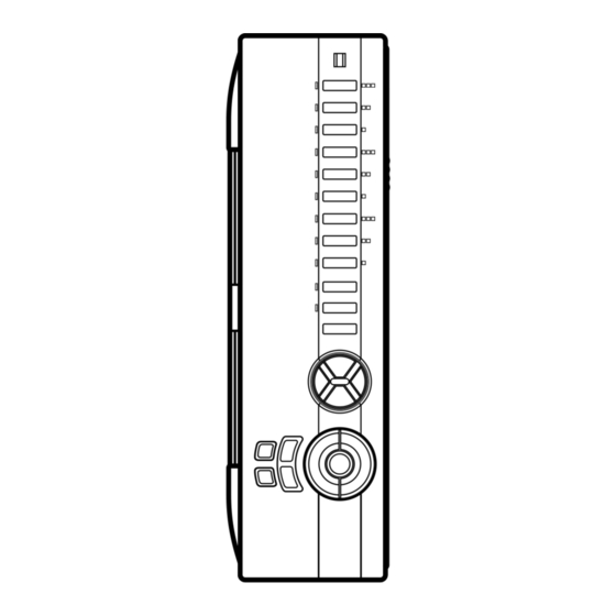
Page 21: Controls And Their Functions
CONTROLS AND THEIR FUNCTIONS FRONT PANEL NATURAL SOUND AV RECEIVER RX–V793 PRESET ROOM 2 STANDBY/ON MEMORY TAPE MONITOR AUTO TUNING SPEAKERS ROOM 2 CONTROL A/B/C/D/E PHONES SPEAKERS BASS TONE EXTENSION BYPASS 0 A B C STANDBY/ON switch Press this switch to turn the power to this unit on. Press it again to turn this unit into the standby mode. - Page 22 BASS EXTENSION switch When this switch is pressed inward (ON), boosts bass frequency response at the main left and main right channels while maintaining overall tonal balance. If you do not have a subwoofer, the use of this switch will be effective to reinforce the bass frequencies.
-
Page 23: Display Panel
DISPLAY PANEL PRESET ROOM 2 MEMORY TAPE MONITOR AUTO TUNING SPEAKERS SPEAKERS ROOM 2 CONTROL Multi-information display Displays various information, for example station frequency, preset station number and name of selected input source. MEMORY indicator When the MEMORY button is pressed, this indicator flashes for about 5 seconds. -
Page 24: Adjustments Before Using This Unit
ADJUSTMENTS BEFORE USING THIS UNIT SELECTING THE OUTPUT MODES SUITABLE FOR YOUR SPEAKER SYSTEM This unit provides you the following four functions to determine the method of distributing output signals to speakers suitable for your audio system. When speaker connections are all completed, select a proper position on each function to make the best use of your speaker system. - Page 25 METHOD OF CHANGING SELECTIONS Operations should be made watching information on this unit’s display panel or the monitor screen. CINEMA DSP NATURAL SOUND AV RECEIVER STANDBY/ON A/B/C/D/E BASS TREBLE BALANCE PHONES SPEAKERS BASS TONE EXTENSION BYPASS If you will use the remote control transmitter, set the TIME/LEVEL·SET MENU switch to the SET MENU position on the remote control transmitter.
-
Page 26: Speaker Balance Adjustment
SPEAKER BALANCE ADJUSTMENT This procedure lets you adjust the sound output level balance between the main, center, and rear speakers using the built-in test tone generator. When this adjustment is performed, the sound output level heard at the listening position will be the same from each speaker. - Page 27 Turn up the volume. Remote control MUTE You will hear a test tone (like pink noise) from the left main speaker, then the center speaker, then the right main speaker, then the right rear speaker, and then the left rear speaker, for about two seconds each.
-
Page 28: Adjustments In The "Set Menu" Mode
ADJUSTMENTS IN THE “SET MENU” MODE The following eight types of functions maximize the performance of your system and expand your enjoyment for audio listening and video watching. 1. CENTER DELAY (C. DELAY) 2. DYNAMIC RANGE (D. RNG) 3. LFE LEVEL (LFE) 4. - Page 29 DESCRIPTIONS OF THE FUNCTIONS 1. CENTER DELAY (Adjusting the delay of center sounds (dialog etc.)) Control range: 0 ms to 5 ms (in 1 ms step) Preset value: 0 ms This adjustment is effective only when the Dolby Digital (AC-3) is decoded and the signals of selected source encoded with the Dolby Digital (AC-3) contain center- channel signals.
-
Page 30: Basic Operations
TO PLAY A SOURCE CINEMA DSP NATURAL SOUND AV RECEIVER STANDBY/ON A/B/C/D/E BASS TREBLE PHONES SPEAKERS BASS TONE EXTENSION BYPASS Note: If you will use the remote control transmitter, be sure to use it with the lid open. Front panel VOLUME ∞... - Page 31 Play the source. (For detailed information on the tuning operation, refer to page 32.) Front panel VOLUME –dB Adjust to the desired output level. If desired, adjust the BASS, TREBLE, BALANCE controls, etc. (refer to page 31) and use the digital sound field processor.
- Page 32 TO RECORD A SOURCE TO TAPE (OR MD) CINEMA DSP NATURAL SOUND AV RECEIVER STANDBY/ON A/B/C/D/E BASS TREBLE BALANCE PHONES SPEAKERS BASS TONE EXTENSION BYPASS Note: If you will use the remote control transmitter, be sure to use it with the lid open. Select the source to be recorded.
-
Page 33: Selecting The Speaker System
Selecting the SPEAKER system Because one or two speaker systems (as main speakers) can be connected to this unit, the SPEAKERS switches allow you to select speaker system A or B, or both at once. SPEAKERS Adjusting the BALANCE control Adjust the balance of the output volume to the left and right speakers to compensate for sound imbalance caused by speaker location or listening room conditions. -
Page 34: Tuning Operations
Normally, if station signals are strong and there is no interference, quick automatic-search tuning (AUTOMATIC TUNING) is possible. However, if signals of the station you want to select are weak, you must tune to it manually (MANUAL TUNING). AUTOMATIC TUNING Select “TUNER”... -
Page 35: Preset Tuning
MANUAL PRESET TUNING This unit can store station frequencies selected by tuning operation. With this function, you can recall any desired station by only selecting the preset station number where it is stored. Up to 40 stations (8 stations x 5 groups) can be stored. CINEMA DSP NATURAL SOUND AV RECEIVER... -
Page 36: Automatic Preset Tuning
AUTOMATIC PRESET TUNING You can also make use of an automatic preset tuning function for FM stations only. By this function, this unit performs automatic tuning and stores FM stations with strong signals sequentially. Up to 40 stations are stored automatically in the same way as in the manual preset tuning method on page 33. -
Page 37: Exchanging Preset Stations
EXCHANGING PRESET STATIONS You can exchange the places of two preset stations with each other as shown below. Example) If you want to shift the preset station on E1 to A5, and vice versa. Recall the preset station on E1 (by following the method of “To recall a preset station”... -
Page 38: Using Digital Sound Field Processor (Dsp)
Dolby Surround. The operation of these decoders can be controlled by selecting a corresponding DSP program including a combined operation of the YAMAHA DSP and the Dolby Digital (AC-3) or the Dolby Pro Logic Surround. - Page 39 To enjoy a video source with the Dolby Pro Logic Surround or Dolby Digital (AC-3) decoded When you select the program No. 1, 2 or 3, and the input signal of the source is 2-channel stereo, Dolby Pro Logic Surround is decoded. When some program is selected and the input signal of the source is encoded with the Dolby Digital (AC- 3), Dolby Digital (AC-3) is automatically decoded.
-
Page 40: Adjusting Delay Time And Each Speaker Output Level
ADJUSTING DELAY TIME AND EACH SPEAKER OUTPUT LEVEL In using the digital sound field processor including the Dolby Pro Logic Decoder or the Dolby Digital (AC-3) Decoder, you can adjust delay time between the main sound and effect sound, and each speaker output level as you prefer. -
Page 41: Adjusting Delay Time
Adjusting delay time You can adjust the time difference between the beginning of the sound from the main speakers and the beginning of the effect sound from the rear or front effect speakers. The larger the value, the later the effect sound is generated. This adjustment can be made to all programs individually. -
Page 42: Brief Overview Of Digital Sound Field Programs
DIGITAL SOUND FIELD PROGRAMS The following list gives you a brief description of the sound fields produced by each of the DSP programs. Keep in mind that most of these are precise digital recreations of actual acoustic environments. The data for these sound fields was recorded at actual locations using sophisticated sound field measurement equipment. - Page 43 PROGRAM TV SPORTS When the input signal is analog or PCM audio: ( Speaker output: main, center, rear When the input signal is Dolby Digital: ( Speaker output: main, center, rear STADIUM When the input signal is analog or PCM audio: ( Speaker output: main, rear When the input signal is Dolby Digital: ( Speaker output: main, center, rear...
-
Page 44: Setting The Sleep Timer
SETTING THE SLEEP TIMER If you use the SLEEP timer of this unit, you can make this unit turn into the standby mode. When you are going to sleep while enjoying a broadcast or other desired input source, this timer function is helpful. Notes The SLEEP timer can be controlled only with the remote control transmitter. -
Page 45: Remote Control Transmitter
The remote control transmitter provided with this unit is designed to control all the most commonly used functions of this unit. If the CD player, tape deck, LD player, DVD player, etc. connected to this unit are YAMAHA components designed for remote control compatibility, then this remote control transmitter will also control various functions of each component. - Page 46 (This switch will not function when the lid is closed.) Normally, set this switch to the “A” position. When controlling a Yamaha LD player or DVD player by using the CD/LD/DVD player keys ( ), set this switch to the “C” position.
- Page 47 If the memory capacity of the remote control transmitter becomes full, no further learning is possible even if some learning-capable keys are not occupied with new functions. If, for example, you store Yamaha codes only into this remote control transmitter, up to about 20 functions can be stored.
- Page 48 52.) USING OPERATION CONTROL KEYS (When the lid is closed) When the lid of the remote control transmitter is closed, you can easily operate Yamaha components including learned functions by using the OPERATION CONTROL keys.
- Page 49 Examples of operations controlled by using the and the (+10) OPERATION CONTROL keys To operate a Yamaha CD player 1. Press the “CD” input selector key. 2. Use the OPERATION CONTROL keys. (They carry out the functions in area A of keys...
- Page 50 MACRO OPERATIONS (When the lid is closed) “Macro” is a command which defines a sequence of several operations. The keys shown in the illustrations below (as preset macro keys) are also preset with macros, in addition to individual functions. Each macro key is preset so that simply pressing it alone will carry out several functions of other keys on this remote control transmitter sequentially.
- Page 51 Preset macro keys and the key functions which they carry out sequentially are as follows. (Also, refer to the table on page 45.) Function of the key (and area) which operates when a macro key is pressed Macro key (Turning the power of this unit on) TAPE TUNER DVD/LD...
-
Page 52: Learning A New Function
LEARNING A NEW FUNCTION Place this remote control transmitter and the other remote control transmitter so that they face each other. This remote control transmitter CLEAR LEARN MACRO (Press by using the point of a mechanical pencil, etc.) * If there is no operation for about 30 seconds after the LEARN button is pressed, the TRANSMIT/LEARN indicator flashes rapidly and the current mode is canceled. -
Page 53: Making A New Macro
MAKING A NEW MACRO A new macro can be programmed onto any preset macro key in place of preset functions. (See page 48 to know what keys are preset macro keys.) You can make as many as 13 new macro keys. A macro key can learn as many as seven functions of other keys. -
Page 54: Clearing Learned Functions
CLEARING LEARNED FUNCTIONS To Clear a Learned Function To clear a learned key function, press the LEARN button using the point of a mechanical pencil, etc. To clear a macro you made, press the MACRO button. CLEAR LEARN MACRO Press and hold the CLEAR button using the point of a mechanical pencil, etc. -
Page 55: Troubleshooting
If the unit fails to operate normally, check the following points to determine whether the fault can be corrected by the simple measures suggested. If it cannot be corrected, or if the fault is not listed in the SYMPTOM column, disconnect the power cord and contact your authorized YAMAHA dealer or service center for help. SYMPTOM... - Page 56 SYMPTOM FM stereo reception is noisy. There is distortion and clear reception cannot be obtained even with a good FM antenna. A desired station cannot be tuned in with the automatic tuning method. Previously preset stations can no longer be tuned in. A desired station cannot be tuned in with the automatic tuning method.
-
Page 57: Specifications
AUDIO SECTION Minimum RMS Output Power per Channel MAIN L/R 8 ohms, 20 Hz to 20 kHz, 0.04% THD ...80W+80W CENTER 8 ohms, 20 Hz to 20 kHz, 0.07% THD ...80W REAR L/R 8 ohms, 20 Hz to 20 kHz, 0.07% THD ...80W+80W Maximum Power [China and General models only]... - Page 58 AM SECTION Tuning Range [U.S.A., Canada, China and General models] ...530 to 1,710 kHz [Australia and Singapore models] ...531 to 1,611 kHz Usable Sensitivity...100 V/m Selectivity ...32 dB Signal-to-Noise Ratio ...50 dB Image Response Ratio ...40 dB Spurious Response Ratio ...50 dB Harmonic Distortion (1 kHz) ...0.3% AUDIO SECTION Output Level/Impedance...
- Page 59 YAMAHA ELECTRONICS (UK) LTD. YAMAHA HOUSE, 200 RICKMANSWORTH ROAD WATFORD, HERTS WD1 7JS, ENGLAND YAMAHA SCANDINAVIA A.B. J A WETTERGRENS GATA 1, BOX 30053, 400 43 VÄSTRA FRÖLUNDA, SWEDEN YAMAHA MUSIC AUSTRALIA PTY, LTD. 17-33 MARKET ST., SOUTH MELBOURNE, 3205 VIC., AUSTRALIA...