Table of Contents
Advertisement
Advertisement
Table of Contents

Related Manuals for Yamaha HTR-5990


Summary of Contents for Yamaha HTR-5990
- Page 1 HTR-5990 AV Receiver OWNER’S MANUAL...
-
Page 2: Important Safety Instructions
IMPORTANT SAFETY INSTRUCTIONS IMPORTANT SAFETY INSTRUCTIONS CAUTION RISK OF ELECTRIC SHOCK DO NOT OPEN CAUTION: TO REDUCE THE RISK OF ELECTRIC SHOCK, DO NOT REMOVE COVER (OR BACK). NO USER-SERVICEABLE PARTS INSIDE. REFER SERVICING TO QUALIFIED SERVICE PERSONNEL. • Explanation of Graphical Symbols The lightning flash with arrowhead symbol, within an equilateral triangle, is intended to alert you to the presence of uninsulated “dangerous voltage”... - Page 3 This product, when installed as indicated in the instructions contained in this manual, meets FCC requirements. Modifications not expressly approved by Yamaha may void your authority, granted by the FCC, to use the product. 2 IMPORTANT: When connecting this product to accessories and/or another product use only high quality shielded cables.
- Page 4 We Want You Listening For A Lifetime YAMAHA and the Electronic Industries Association’s Consumer Electronics Group want you to get the most out of your equipment by playing it at a safe level. One that lets the sound come through loud and clear without annoying blaring or distortion –...
-
Page 5: Table Of Contents
INTRODUCTION FEATURES... 2 GETTING STARTED... 3 Supplied accessories ... 3 Preparing the remote control ... 4 CONTROLS AND FUNCTIONS ... 5 Front panel ... 5 Remote control... 7 Front panel display ... 9 Rear panel ... 11 PREPARATION CONNECTIONS ... 12 Before connecting speakers ... -
Page 6: Features
Center: 120 W Surround: 120 W + 120 W Surround Back: 120 W + 120 W Sound field features ◆ Proprietary YAMAHA technology for the creation of sound fields ◆ THX Select2 ◆ Dolby Digital/Dolby Digital EX decoder ◆ DTS/DTS-ES Matrix 6.1, Discrete 6.1, DTS Neo:6 decoder, DTS 96/24 ◆... -
Page 7: Getting Started
Supplied accessories Please check that you received all of the following parts. Remote control POWER POWER POWER STANDBY AUDIO SEL SLEEP PHONO TUNER MULTI CH IN V-AUX CBL/SAT MD/TAPE CD-R VCR 1 DVR/VCR2 SELECT SOURCE TV VOL VOLUME – – –... -
Page 8: Preparing The Remote Control
GETTING STARTED Preparing the remote control ■ Installing batteries Press the part and slide the battery compartment cover off. Insert four supplied batteries (AAA, R03) according to the polarity markings on the inside of the battery compartment. Slide the cover back until it snaps into place. If the remote control is without batteries for more than 2 minutes, or if exhausted batteries remain in the remote control, the contents of the memory may be... -
Page 9: Controls And Functions
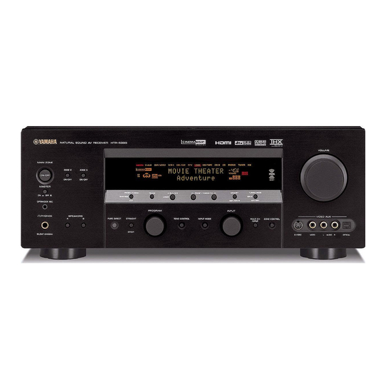
CONTROLS AND FUNCTIONS Front panel Note The XM Satellite Radio controls (SEARCH MODE, CATEGORY, PRESET/TUNING/CH l / h, MEMORY and DISPLAY) are only applicable to the U.S.A. model and are operational only when XM is selected as the input source. For details, see “Front panel functions”... - Page 10 CONTROLS AND FUNCTIONS 7 FM/AM Switches the reception band (FM or AM) when TUNER is selected as the input source (see page 44). Note The frequency of the previously received station is automatically recalled. 8 A/B/C/D/E Selects one of the 5 preset station groups (A to E) when TUNER is selected as the input source (see page 48).
-
Page 11: Remote Control
Remote control This section describes the function of each control on the remote control used to control this unit. Set AMP/ SOURCE/TV to AMP to operate this unit. To operate other components, see “REMOTE CONTROL FEATURES” on page 90. Note The XM Satellite Radio controls (XM, XM MEMORY, SRCH MODE, DISPLAY, cursor buttons k / n / l / h, numeric buttons and ENT.) are only applicable to the U.S.A. - Page 12 CONTROLS AND FUNCTIONS A STANDBY Sets this unit, Zone 2 and Zone 3 to the standby mode (see page 28). Note This button is operational only when MASTER ON/OFF on the front panel is pressed inward to the ON position. B POWER Turns on this unit, Zone 2 and Zone 3 (see page 28).
-
Page 13: Front Panel Display
Front panel display Note The XM indicator is only applicable to the U.S.A. model. 1 2 3 V-AUX DVR/VCR 2 VCR 1 DIGITAL PL x YPAO HiFi DSP DISCRETE SILENT VIRTUAL MATRIX CINEMA 1 YPAO indicator Lights up when the AUTO SETUP procedure is in progress and when the AUTO SETUP speaker settings are used without any modifications. - Page 14 CONTROLS AND FUNCTIONS K 96/24 indicator Lights up when a DTS 96/24 signal is input to this unit. L LFE indicator Lights up when the input signal contains an LFE signal. M Input channel and speaker indicators Input channel indicators Indicate the channel components of the current digital input signal.
-
Page 15: Rear Panel
Rear panel DIGITAL INPUT COMPONENT VIDEO VIDEO COAXIAL S VIDEO VIDEO DVR/ VCR 2 OPTICAL CBL/ RS-232C MONITOR OUT IN 1 CBL/SAT MD/TAPE IN 2 CD-R DIGITAL OUTPUT MONITOR OUT HDMI 1 DIGITAL OUTPUT jacks See pages 22, 23 and 25 for connection information. 2 DIGITAL INPUT jacks See pages 22, 23 and 25 for details. -
Page 16: Connections
Ideally, they should be positioned at the same width as the front speakers. Subwoofer The use of a subwoofer, such as the YAMAHA Active Servo Processing Subwoofer System, is effective not only for reinforcing bass frequencies from any or all channels,... -
Page 17: Connecting Speakers
SURROUND ZONE 2(3) terminals Connect surround speakers to these terminals. SUBWOOFER jack Connect a subwoofer with a built-in amplifier, such as the YAMAHA Active Servo Processing Subwoofer System, to this jack. SURROUND BACK terminals Connect surround back speakers to these terminals. - Page 18 CONNECTIONS Remove approximately 10 mm (3/8 in) of insulation from each of the speaker cables. 10 mm (3/8 in) Twist the exposed wires of the cable together to prevent short circuits. Loosen the knob using the supplied speaker terminal wrench. Speaker terminal wrench Red: positive (+) Black: negative (–)
- Page 19 PRESENCE/ZONE 2(3) terminals Connect presence speakers to these terminals. Note You can also use these terminals to connect the Zone 2 speakers (see page 103). Open the tab. Insert one bare wire into the hole of each terminal. Return the tab to secure the wire. ■...
- Page 20 CONNECTIONS (U.S.A. model) • You can connect both surround back and presence speakers to this unit, but they do not output sound simultaneously. You can set to prioritize either set of speakers using the PRIORITY parameter in MANUAL SETUP (see page 77). •...
-
Page 21: Using Bi-Wire And Bi-Amp Connections
Using bi-wire and bi-AMP connections Some of the speakers commercially available these days have speaker wire connections that allow bi-wiring or bi- amplification to enhance the performance of the speaker system. This unit allows you to make bi-wire and bi-AMP connections to one speaker system. -
Page 22: Information On Cables And Jacks Used For Connections
CONNECTIONS Information on cables and jacks used for connections CAUTION Do not connect this unit or other components to the main power until all connections between components are complete. ■ Cable indications For analog signals left analog cables right analog cables For digital signals optical cables coaxial cables... -
Page 23: Audio Jacks
■ Audio jacks This unit has four types of audio jacks (analog audio, digital audio coaxial, digital audio optical and HDMI). Connection depends on the availability of audio jacks on your other components. AUDIO AUDIO jacks For conventional analog audio signals. DIGITAL AUDIO (COAXIAL) jacks For digital audio signals transmitted via digital coaxial cables. - Page 24 CONNECTIONS ■ Video jacks This unit has four types of video jacks (composite, component, S-video and HDMI). Connection depends on the availability of input jacks on your monitor. When V CONV. is set to ON (see page 83), the analog video signals input at the VIDEO, S VIDEO and COMPONENT VIDEO jacks can be output at the VIDEO, S VIDEO and COMPONENT VIDEO jacks interchangeably.
-
Page 25: Connecting Hdmi Components
Connecting HDMI components This unit has the HDMI IN 1 and HDMI IN 2 jacks for digital audio and video signal input as well as the HDMI OUT jack for digital audio and video signal output. Connect the HDMI IN 1 or HDMI IN 2 jack of this unit to the HDMI OUT jack of other HDMI components (such as a DVD player). -
Page 26: Connecting Video Components
CONNECTIONS Connecting video components ■ Connecting a DVD player HDMI out Optical out Coaxial out DIGITAL INPUT OPTICAL DIGITAL OUTPUT Note Check the availability of jacks on your DVD player and select one type of connection for audio/video input/output. However, in case you make an HDMI connection, you can make both audio and video connections using a single HDMI cable. -
Page 27: Connecting Other Video Components
■ Connecting other video components HDMI out Optical out DIGITAL INPUT VCR 2 OPTICAL IN 1 CBL/SAT IN 2 DIGITAL OUTPUT HDMI HDMI out Note Check the availability of jacks on your other video components and select one type of connection for audio/video input/output. However, in case you make an HDMI connection, you can make both audio and video connections using a single HDMI cable. -
Page 28: Connecting To The Video Aux Jacks On The Front Panel
CONNECTIONS ■ Connecting to the MULTI CH INPUT jacks This unit is equipped with 6 additional input jacks (left and right FRONT, CENTER, left and right SURROUND and SUBWOOFER) for discrete multi-channel input from a multi-format player, external decoder, sound processor or pre-amplifier. -
Page 29: Connecting Audio Components
Connecting audio components Optical in CD recorder Audio in DIGITAL INPUT COAXIAL OPTICAL MD/TAPE CD-R DIGITAL OUTPUT Optical out Coaxial out Notes • Check the availability of jacks on your audio components and select one type of connection for audio/video input/output. •... -
Page 30: Connecting An External Amplifier
2 SURROUND PRE OUT jacks Surround channel line output jacks. 3 SUBWOOFER PRE OUT jack Connect a subwoofer with built-in amplifier, such as the YAMAHA Active Servo Processing Subwoofer System, to this jack. 4 SURROUND BACK/PRESENCE PRE OUT jacks Surround back or presence channel line output jacks. If you only connect one external amplifier for the surround back channel, connect it to the left (L) jack. -
Page 31: Connecting The Antennas
• A property installed outdoor antenna provides clearer reception than an indoor one. If you experience poor reception quality, an outdoor antenna may improve the quality. Consult the nearest authorized YAMAHA dealer or service center about outdoor antennas. CONNECTIONS AM loop antenna... -
Page 32: Connecting The Power Cable
CONNECTIONS Connecting the power cable ■ Connecting the AC power cable Plug the supplied AC power cable into the AC inlet after all other connections are complete, then plug the AC power cable to an AC wall outlet. CAUTION Use the supplied AC cable. Do not use other AC power cables as doing so may result in fire hazard or electrical shock. -
Page 33: Setting The Speaker Impedance
Press MAIN ZONE ON/OFF, ZONE 2 ON/OFF or ZONE 3 ON/OFF on the front panel (or POWER on the remote control) to turn on this unit, Zone 2 or Zone 3. ON/OFF Front panel Remote control • When MASTER ON/OFF is pressed inward to the ON position, you can also press POWER or STANDBY on the remote control to turn on or set this unit, Zone 2 and Zone 3 to the standby mode simultaneously. -
Page 34: Auto Setup
AUTO SETUP Introduction This receiver employs YAMAHA Parametric Room Acoustic Optimizer (YPAO) technology which lets you avoid troublesome listening-based speaker setup and achieves highly accurate sound adjustments. The supplied optimizer microphone collects and analyzes the sound your speakers produce in your actual listening environment. -
Page 35: Using Auto Setup
Using AUTO SETUP For best results, make sure the room is as quiet as possible during the AUTO SETUP procedure (YPAO). If there is too much ambient noise, the results may not be satisfactory. • You can run AUTO SETUP using the system menu that appears in the OSD or in the front panel display. - Page 36 AUTO SETUP Press k / n repeatedly to select WIRING, DISTANCE, SIZE, EQ or LEVEL. 1 AUTO:MENU . SETUP;;;;;;;AUTO WIRING;;;;;;CHECK DISTANCE;;;;CHECK SIZE;;;;;;;;CHECK EQ;;;;;;;;;;NATURAL LEVEL;;;;;;;CHECK START [ ]/[ ]:Up/Down [<]/[>]:Adjust When WIRING, DISTANCE, SIZE or LEVEL is selected, press l / h to select: CHECK To automatically check and adjust the selected item.
- Page 37 Notes • If you change speakers, speaker positions, or the layout of your listening environment, run AUTO SETUP again to re-calibrate your system. • In the DISTANCE results, the distance displayed may be longer than the actual distance depending on the characteristics of your subwoofer.
-
Page 38: Playback
PLAYBACK CAUTION Extreme caution should be exercised when you play back CDs encoded in DTS. If you play back a CD encoded in DTS on a DTS-incompatible CD player, you will only hear some unwanted noise that may damage your speakers. Check whether your CD player supports CDs encoded in DTS. Also, check the sound output level of your CD player before you play back a CD encoded in DTS. - Page 39 Rotate VOLUME on the front panel (or press VOLUME +/– on the remote control) to adjust the volume to the desired output level. VOLUME Front panel Rotate the PROGRAM selector on the front panel (or press one of the sound field program buttons on the remote control) to select the desired sound field program.
-
Page 40: Additional Operations
PLAYBACK Additional operations ■ Adjusting the tonal quality Use this feature to adjust the balance of bass and treble for the front L/R and center speaker channels. Press TONE CONTROL on the front panel repeatedly to select TREBLE or BASS. TONE CONTROL Rotate the PROGRAM selector to adjust the high-frequency response (TREBLE) or the... - Page 41 ■ Selecting the MULTI CH INPUT Press MULTI CH INPUT on the front panel or MULTI CH IN on the remote control so that MULTI CH INPUT appears in the front panel display and on the video monitor. MULTI CH INPUT Front panel Note...
- Page 42 PLAYBACK ■ Enjoying 2-channel software in surround Signals input from 2-channel sources can also be played back in multiple channels. Set AMP/SOURCE/TV to AMP and then press STANDARD on the remote control to switch between the Surround and Enhanced programs. SOURCE You can also press MOVIE or THX on the remote control to select the MOVIE THEATER or THX...
- Page 43 ■ Using PURE DIRECT PURE DIRECT bypasses the decoders and DSP processors of this unit as well as shuts down the video circuitry, allowing you to enjoy the highest possible sound fidelity from analog and PCM sources. Notes • To avoid unexpected noise, do not play DTS-encoded CDs in the PURE DIRECT mode.
-
Page 44: Using The Sleep Timer
PLAYBACK ■ Using the sleep timer Use this feature to automatically set this unit in the standby mode after a certain amount of time. The sleep timer is useful when you are going to sleep while this unit is playing or recording a source. The sleep timer also automatically turns off any external components connected to the AC OUTLETS. -
Page 45: Selecting Audio Input Modes
Press STRAIGHT (EFFECT) on the front panel or on the remote control again to turn the sound effect back on. STRAIGHT disappears from the front panel display. STRAIGHT EFFECT Front panel Remote control ■ Virtual CINEMA DSP Virtual CINEMA DSP allows you to enjoy the CINEMA DSP programs without surround speakers. - Page 46 PLAYBACK • We recommend using AUTO in most cases. • You can designate the default input mode to be selected when the power of this unit is turned on (see page 84). Notes • If the digital output data of the player has been processed in any way, you may not be able to perform DTS decoding even if you make a digital connection between this unit and the player.
-
Page 47: Recording
Recording adjustments and other operations are performed from the recording components. Refer to the operation instructions for those components. MAIN ZONE ZONE 2 ZONE 3 ON/OFF ON/OFF ON/OFF MASTER l PRESET/TUNING/CH h PRESET/TUNING FM/AM A/B/C/D/E MEMORY :OFF SEARCH MODE CATEGORY EDIT MAN'L/AUTO FM OPTIMIZER MIC... -
Page 48: Fm/Am Tuning
FM/AM TUNING Automatic tuning Automatic tuning is effective when station signals are strong and there is no interference. MAIN ZONE ZONE 2 ZONE 3 ON/OFF ON/OFF ON/OFF MASTER PRESET/TUNING FM/AM A/B/C/D/E l PRESET/TUNING/CH h :OFF SEARCH MODE CATEGORY EDIT OPTIMIZER MIC PROGRAM INPUT PHONES... -
Page 49: Manual Tuning
Manual tuning Manual tuning is effective when stations signals are weak. Manually tuning into an FM station will automatically change the reception mode to monaural reception to increase the signal quality. Repeat steps 1 and 2 in “Automatic tuning” to select TUNER and the reception band. Press TUNING MODE (AUTO/MAN’L) repeatedly so that the AUTO indicator disappears from the front panel display. - Page 50 FM/AM TUNING Press and hold MEMORY (MAN’L/AUTO FM) on the front panel for more than 3 seconds. The preset group and number as well as the MEMORY and AUTO indicators flash. After approximately 5 seconds, automatic presetting starts from the currently selected frequency and proceeds toward the higher frequencies.
-
Page 51: Manual Preset Tuning
Manual preset tuning You can also store up to 40 FM or AM stations (8 stations in each of the 5 groups, A1 to E8) manually. Note You must first set AMP/SOURCE/TV to SOURCE and then press TUNER on the remote control to select TUNER as the input source. -
Page 52: Selecting Preset Stations
FM/AM TUNING Press MEMORY (MAN’L/AUTO FM) on the front panel while the MEMORY indicator is flashing. The station band and frequency appear in the front panel display with the preset group and number you have selected. MEMORY MAN'L/AUTO FM V-AUX DVR/VCR 2 VCR 1 CBL/SAT... -
Page 53: Exchanging Preset Stations
Press PRESET/TUNING/CH l / h (or PRESET k / n on the remote control) to select a preset station number (1 through 8). The preset group and number appear in the front panel display along with the station band, frequency and the TUNED indicator lights up. -
Page 54: Xm Satellite Radio Tuning
XM SATELLITE RADIO TUNING XM SATELLITE RADIO TUNING What is XM Satellite Radio? XM Satellite Radio is the satellite radio service with millions of listeners across the United States broadcasting live daily. The XM Satellite Radio channel lineup includes more than 130 digital channels of choice from coast to coast: 68 commercial-free music channels, featuring hip hop to opera, classical to country, bluegrass to blues;... -
Page 55: Xm Satellite Radio Controls And Functions
XM Satellite Radio controls and functions This section describes the functions of each control used for XM Satellite Radio tuning. Note The following controls are only available when XM is selected as the input source. Rotate the INPUT selector on the front panel (or set AMP/SOURCE/TV to SOURCE and then press XM on the remote control) to select XM as the input source. -
Page 56: Activating Xm Satellite Radio
XM SATELLITE RADIO TUNING Activating XM Satellite Radio To sign up for an account with the XM Satellite Radio service, an XM Satellite Radio ID number is required. Follow the procedure below to check your ID number, and then access the website at “http://activate.xmradio.com/” or call “1-800-XM-RADIO (1-800-967-2346)”... -
Page 57: Selecting The Xm Satellite Radio Mode
Selecting the XM Satellite Radio mode MAIN ZONE ZONE 2 ZONE 3 ON/OFF ON/OFF ON/OFF MASTER PRESET/TUNING FM/AM A/B/C/D/E l PRESET/TUNING/CH h MEMORY :OFF SEARCH MODE CATEGORY EDIT MAN'L/AUTO FM OPTIMIZER MIC PROGRAM INPUT PHONES SPEAKERS PURE DIRECT STRAIGHT TONE CONTROL AUDIO SELECT EFFECT SILENT CINEMA... -
Page 58: Category Search Mode
XM SATELLITE RADIO TUNING To change the channel category, press CATEGORY (or A-E/CAT. l / h on the remote control) repeatedly. A/B/C/D/E CATEGORY Front panel To search a channel within all channels, press PRESET/TUNING/CH l / h (or PRESET/CH k / n on the remote control) repeatedly. - Page 59 ■ Preset Search mode Prior to selecting a preset channel in the Preset Search mode, you should preset XM Satellite Radio channels. For details, see “Setting XM Satellite Radio preset channels” on page 56. All preset channels (A1 to E8) recalls 001 Preview by the factory setting.
-
Page 60: Setting Xm Satellite Radio Preset Channels
XM SATELLITE RADIO TUNING Press the numeric buttons to enter the desired channel number. For example, to enter the number 123, press the numeric buttons as shown below. STEREO MUSIC The display changes as follows. V-AUX DVR/VCR 2 VCR 1 CBL/SAT MD/TAPE <... - Page 61 While the MEMORY indicator is flashing, press CATEGORY (or A-E/CAT. l / h on the remote control) to select a preset group (A to E). The group letter appears. A/B/C/D/E CATEGORY Front panel V-AUX DVR/VCR 2 VCR 1 CBL/SAT MD/TAPE [ 0 4 0 ] D e e p S c i - F i Preset group...
-
Page 62: Displaying The Xm Satellite Radio Information
XM SATELLITE RADIO TUNING Displaying the XM Satellite Radio information You can display XM information (such as channel number/name, category, or artist name/song title) for the channel currently selected in the OSD and in the front panel display. You can select the amount of time while the XM Satellite Radio information is displayed in the OSD (see page 86). -
Page 63: Editing Sound Field Parameters
The acoustics in your room could be changed to those of a concert hall, a dance floor, or virtually any size room at all. This ability to create sound fields at will is exactly what YAMAHA has done with the digital sound field processor. EDITING SOUND FIELD PARAMETERS... - Page 64 EDITING SOUND FIELD PARAMETERS Select the sound field program you want to adjust. STEREO MUSIC ENTERTAIN MOVIE STANDARD SELECT EXTD. SUR MEMORY A SPEAKERS Sound field category MUSIC Cursor P o p / R o c k D S P L E V E L ; ; ; ; 0 d B P .
-
Page 65: Sound Field Program Descriptions
The YAMAHA CINEMA DSP modes are compatible with all Dolby Digital, DTS, and Dolby Surround sources. Set the input mode to AUTO (see page 41) to enable this unit to automatically switch to the appropriate digital decoder according to the input signal. -
Page 66: Thx Cinema
SOUND FIELD PROGRAM DESCRIPTIONS Remote Category Source control button Program THX Cinema MULTI THX Game 2-CH THX Select2 Cinema STANDARD DOLBY DIGITAL STANDARD D+PL x Movie STANDARD DOLBY D EX STANDARD STANDARD DTS 96/24 MULTI STANDARD DTS+PL x Movie STANDARD DTS+DOLBY EX STANDARD DTS ES... -
Page 67: For Music Sources
For music sources You can select from the following sound fields when playing music sources, like CD, FM/AM broadcasting, tapes, etc. Program selection methods vary depending on sound field program types. For details on how to select sound field programs, see “Basic operations” on page 34. Remote Category Source... -
Page 68: Sound Field Parameter Descriptions
SOUND FIELD PARAMETER DESCRIPTIONS SOUND FIELD PARAMETER DESCRIPTIONS You can adjust the values of certain digital sound field parameters so the sound fields are recreated accurately in your listening room. Not all of the following parameters are found in every program. ■... - Page 69 ■ LIVENESS (Liveness) Function: Adjusts the reflectivity of the virtual walls in the hall by changing the rate at which the early reflections decay. Description: The early reflections of a source sound decay much faster in a room with acoustically absorbent wall surfaces than in one which has highly reflective surfaces.
- Page 70 SOUND FIELD PARAMETER DESCRIPTIONS ■ REV. TIME (Reverberation time) Function: Adjusts the amount of time it takes for the dense, subsequent reverberation sound to decay by 60 dB (at 1 kHz). This changes the apparent size of the acoustic environment over an extremely wide range. Description: The longer the reverberation time, the more live the listening room environment seems.
- Page 71 ■ DIALOG LIFT (Dialog lift) Function: Adjusts the height of the front and center channel sounds by assigning some of the front and center channel elements to the presence speakers. Description: The larger the parameter, the higher the position of the front and center channel sound. Choices: 0, 1, 2, 3, 4, 5 For 7ch Stereo...
- Page 72 SOUND FIELD PARAMETER DESCRIPTIONS ■ DECODE TYPE (Decoder type) For MOVIE THEATER Function: Selects the decoder used to playback 2-channel sources using MOVIE THEATER programs. Choices: Pro Logic / Pro Logic x / Neo:6 For THX Cinema Function: Selects the decoder used to playback 2-channel sources using THX Cinema. Choices: Pro Logic / Pro Logic x / Neo:6 For SURROUND Standard...
-
Page 73: Sound Field Program Speaker Layouts
SOUND FIELD PROGRAM SPEAKER LAYOUTS Sound output from each speaker depends on the type of audio signals being input. Refer to the following diagrams in the table below to understand the speaker layout for each sound field program. Note Be advised that there may be no or not enough sound output from speakers depending on the type of input source being played back. Furthermore, there may be some channels that can only be used partially when they are adjusted to specific aspects of movies, such as special sound effects, etc. - Page 74 SOUND FIELD PROGRAM SPEAKER LAYOUTS 2-channel audio (monaural) MUSIC Hall in Vienna The Bttm Line The Roxy Thtr ENTERTAINMENT Disco MUSIC Pop/Rock ENTERTAINMENT Variety/Sports Mono Movie Game THX Cinema THX Surround THX Select2 Cinema THX Music THX Game STANDARD DOLBY DIGITAL PRO LOGIC PRO LOGIC MOVIE THEATER...
- Page 75 2-channel audio (monaural) STANDARD PLIIx Movie PLII Music PLII Game Movie/Game Music MOVIE THEATER Enhanced PLII Movie STANDARD Neo:6 Cinema Neo:6 Music Cinema Music SOUND FIELD PROGRAM SPEAKER LAYOUTS 5.1/6.1-channel 2-channel audio (stereo) audio * Movie/Music/Game When Priority is set to PRNS When Priority is set to SB...
- Page 76 SOUND FIELD PROGRAM SPEAKER LAYOUTS 2-channel audio (monaural) MOVIE THEATER Enhanced Neo:6 Cinema STRAIGHT Monaural playback PURE DIRECT Monaural playback 2-channel audio 5.1/6.1-channel (stereo) audio * When Priority is set to PRNS When Priority is set to SB 5.1/6.1-channel 5.1/6.1-channel audio * audio *...
-
Page 77: Manual Setup
You can use the following parameters in SET MENU to manually adjust a variety of system settings and customize the way this unit operates. Change the initial settings (indicated in bold under each parameter) to reflect the needs of your listening environment. -
Page 78: Option Menu
MANUAL SETUP 4 OPTION MENU Use to manually adjust the optional system settings. Item A)DISPLAY SET Adjusts the settings for the OSD and the front panel display and converts video signals. B)MEMORY GUARD Locks sound field program parameters and other SET MENU settings. C)AUDIO SELECT Selects the type of input signal to be used. -
Page 79: Using Manual Setup
Using MANUAL SETUP Use the remote control to access and adjust each parameter. SOURCE TV VOL VOLUME – – – TV MUTE TV INPUT MUTE PRESET/CH LEVEL SET MENU PURE DIRECT TITLE MENU BAND SRCH MODE NIGHT ENTER AUDIO A-E/CAT. STRAIGHT ON SCREEN RETURN... -
Page 80: Using Basic Menu
MANUAL SETUP Using BASIC MENU Use to manually adjust basic system parameters. 1 BASIC MENU 1/2 . A)SPEAKER SET . E)TEST TONE B)SP LEVEL C)SP DISTANCE D)THX SET [ ]/[ ]:Up/Down [ENTER]:Enter ■ Speaker set A)SPEAKER SET Use to manually adjust any speaker setting. If you are not satisfied with the bass sounds from your speakers, you can change these settings according to your preference. - Page 81 Surround back speakers SB L/R SP Choices: LRGx2, LRGx1, SMLx2, SMLx1, NONE SB L/R SP SMLx1 [SMLx2 • Select LRGx2 if you have 2 large surround back speakers. The unit directs the entire range of the surround back channel signal to the surround back speakers.
- Page 82 MANUAL SETUP ■ Speaker level B)SP LEVEL Use these settings to manually balance the speaker levels between the front left (or surround left) speaker and each speaker selected in SPEAKER SET (page 76). Choices: –10.0 dB to +10.0 dB Initial setting: 0.0 dB B)SP LEVEL .
-
Page 83: Using Sound Menu
■ THX set D)THX SET Use to manually adjust the THX settings. D)THX SET SB DIST. 0.3-1.2m [<]/[>]:Adjust Surround back speaker distance SB DIST. Use this feature to optimize the surround sound field when you have to place the surround back L/R speakers apart. Choices: under 0.3m, 0.3 –... - Page 84 HDMI OUT jack on the rear panel of this unit. Choices: HTR-5990, OTHER • Select HTR-5990 to play back HDMI audio signals on this unit. The HDMI audio signals input at the HDMI IN jacks of this unit are not output to the HDMI component connected to the HDMI OUT jack on the rear panel of this unit.
-
Page 85: Using Input Menu
Using INPUT MENU Use to reassign digital input/outputs, select the input mode or rename your inputs. 3 INPUT MENU 1/2 3 INPUT MENU 2/2 . A)I/O ASSIGNMENT . E)MULTI CH SET B)INPUT RENAME C)VOLUME TRIM D)DECODER MODE [ ]/[ ]:Up/Down [ ]/[ ]:Up/Down [ENTER]:Enter [ENTER]:Enter... - Page 86 MANUAL SETUP ■ Input rename B)INPUT RENAME Use this feature to change the name of the inputs in the OSD and front panel display. B)INPUT RENAME -> [<]/[>]:Position [ ]/[ ]:Chara. Press an input selector button to select the input you want to change the name of. Set AMP/SOURCE/TV to AMP.
-
Page 87: Using Option Menu
Using OPTION MENU Use to manually adjust the optional system settings. 4 OPTION MENU 1/2 4 OPTION MENU 2/2 . A)DISPLAY SET . E)PARAM. INI B)MEMORY GUARD F)ZONE SET C)AUDIO SELECT G)XM RADIO SET D)DECODER MODE [ ]/[ ]:Up/Down [ ]/[ ]:Up/Down [ENTER]:Enter [ENTER]:Enter ■... - Page 88 MANUAL SETUP HDMI interlace/progressive up-conversion HDMI I/P Use this feature to activate or deactivate the HDMI I/P up- conversion of the analog video signals input at the composite video, S-video and component video jacks so that the analog video signals deinterlaced from 480i to 480p are output at the HDMI OUT jack.
- Page 89 ■ Parameter initialization E)PARAM. INI Use this feature to initialize the parameters for each sound program within a sound program group. When field field you initialize a sound program group, all of the field parameter values within that group revert to their initial settings.
- Page 90 MANUAL SETUP Zone 3 amplifier ZONE3 AMP Use to select how the ZONE 3 speakers will be amplified. Choices: EXT, SUR, PRNS, BOTH • Select EXT if you want to connect your Zone 3 speakers through an external amplifier connected to the ZONE 3 OUTPUT jacks on the rear panel of this unit.
-
Page 91: Advanced Operations
You can switch between the available OSD modes and manually adjust the output level of each speaker. Selecting the OSD mode You can display the operating information of this unit on a video monitor. If you display the SET MENU and sound field program parameter settings on a monitor, it is much easier to see the available options and parameters than it is to read the information in the front panel display. -
Page 92: Advanced Setup
ADVANCED SETUP This unit has additional menus that are displayed in the front panel display. The ADVANCED SETUP menu offers additional operations to adjust and customize the way this unit operates. Change the initial settings (indicated in bold under each parameter) to reflect the needs of your listening environment. Using ADVANCED SETUP Press MASTER ON/OFF on the front panel to release it outward to the OFF position to set... - Page 93 ■ Remote sensor REMOTE SEN Use to activate or deactivate the signal-receiving capability of the remote control sensor on the front panel of this unit. Choices: ON, OFF • Select ON if you want to activate the signal-receiving capability of the remote control sensor. •...
-
Page 94: Remote Control Features
In addition to controlling this unit, the remote control can also operate other audio and video components made by YAMAHA and other manufacturers. To control these other components, you must set up the remote control with the appropriate remote control codes. This remote control also has a learn feature which allows the remote to acquire functions from other remote controls equipped with an infrared remote control transmitter. -
Page 95: Controlling Each Component
Controlling each component Once you set the appropriate remote control codes, you can use this remote to control your other components. Note that some buttons may not correctly operate the selected component. Use the input selector buttons to select the component you want to operate. The remote control automatically switches to the appropriate control mode for that component. -
Page 96: Setting Remote Control Codes
VCR 1 DVR/VCR2 Note You may not be able to operate your YAMAHA component even if a YAMAHA remote control code is preset as listed above. In this case, try setting another YAMAHA remote control code. Set AMP/SOURCE/TV to SOURCE. - Page 97 Notes • You need to set the corresponding remote control AMP ID (see page 89). • When using multiple YAMAHA receivers/amplifiers, you may be able to operate the other components simultaneously with the default code setting. In this case, set one of the alternative codes to operate this unit separately.
-
Page 98: Using Learn
• The supplied remote control does not contain all possible codes for commercially available audio and video components (including YAMAHA components). If operation is not possible with any of the remote control codes, program the new remote control function using the Learn feature (see “Using LEARN”) or use the remote control supplied with the component. - Page 99 Press LEARN using a ballpoint pen or similar object. LEARN and the selected component name (ex. DVD) appear alternately in the display window. LEARN Notes • Do not press and hold LEARN. If you hold it down for more than 3 seconds, the remote enters the remote control code setting mode.
-
Page 100: Using Re-Name
REMOTE CONTROL FEATURES Using RE-NAME You can change the name of the input source that appears in the display window on the remote control if you want to use a different name than the factory preset. This is useful when you have set the input selector to control a different component. -
Page 101: Using Macro
DVR/VCR2 You can turn on some components (including YAMAHA components) connected to this unit by connecting them to the AC OUTLETS on the rear panel of this unit. (Power control may not be synchronized with this unit depending on the component. - Page 102 REMOTE CONTROL FEATURES ■ MACRO operations Macro buttons (U.S.A. model) POWER POWER STANDBY POWER FREQ/RDS FREQ/RDS AUDIO SEL SLEEP DISC SKIP PHONO TUNER MULTI CH IN V-AUX CBL/SAT MD/TAPE CD-R VCR 1 DVR/VCR2 MACRO ON/OFF Set MACRO ON/OFF to ON. Press a macro button.
-
Page 103: Using Clear
Press the buttons for the functions you want to include in the macro operation in sequence. You can set up to 10 steps (10 functions). After you have set 10 steps, FULL appears and the remote control automatically exits the macro mode. (U.S.A. -
Page 104: Clearing A Learned Function
REMOTE CONTROL FEATURES Release the object used to press CLEAR to exit from the clearing mode. CLEAR Notes • C;NG appears in the display window if clearing was unsuccessful. In this case start over from step 3. • ERROR appears in the display window if you press a button not indicated in the respective step, or if you press more than one button simultaneously. -
Page 105: Clearing A Macro Function
■ Clearing a macro function You can clear the function programmed for a certain macro button. Set AMP/SOURCE/TV to AMP or SOURCE. SOURCE Press MACRO using a ballpoint pen or similar object. “MCR ?” appears in the display window. MACRO Note If you do not complete each of the following steps within 30 seconds, the macro programming mode will be... -
Page 106: Zone 2/Zone 3
YAMAHA dealer or service center for the Zone 2 and Zone 3 connections that best meet your requirements. • Some YAMAHA models are able to connect directly to the CONTROL OUT jack on this unit. If you own these products, you may not need to use an infrared emitter. -
Page 107: Selecting Zone 2 Or Zone 3
■ Using the internal amplifiers of this unit If you want to use one internal amplifier (surround or surround back) of this unit Connect the Zone 2 or Zone 3 speakers directly to the SURROUND/ZONE 2(3) or PRESENCE/ZONE 2(3) speaker terminals and select either SUR or PRNS for ZONE2 AMP or ZONE3 AMP (see pages 85 and 86). -
Page 108: Controlling Zone 2 And Zone 3
ZONE 2/ZONE 3 • You must complete this step within 5 seconds while the selected zone flashes in the front panel display. Otherwise, the currently selected zone mode is automatically canceled. In this case, press ZONE CONTROL again. • The initial setting is ZONE2 when both Zone 2 and Zone 3 are turned on. -
Page 109: Using The Control Mode Of Zone 2 And Zone 3
■ Adjusting the volume level of Zone 2 or Zone 3 Rotate VOLUME on the front panel (or press VOLUME +/– on the remote control) to adjust the volume level of the selected zone. Control range: –80 dB to +16.5 dB Control step: 0.5 dB VOLUME Note... -
Page 110: Hdmi
HDMI What is HDMI? HDMI (High-Definition Multimedia Interface) is the first industry-supported, uncompressed, all-digital A/V (audio/ video) interface. Providing an interface between any A/V source (such as a set-top box or A/V receiver) and an audio/video monitor (such as a digital television – DTV), HDMI supports standard, enhanced or high-definition video as well as multi-channel digital audio using a single cable. -
Page 111: Setting The Hdmi Parameters
Setting the HDMI parameters ■ Assigning HDMI components You can assign an HDMI component to the HDMI IN 1 or HDMI IN 2 jack on the rear panel of this unit so that the audio and video signals input via HDMI connection can be simultaneously played back. -
Page 112: Troubleshooting
Set the input mode to AUTO or COAX/OPT. Play a source whose signals this unit can reproduce. Connect HDMI components that support the HDCP copy protection standards. Set SUPPORT AUDIO to HTR-5990 in MANUAL SETUP. Set V CONV. to ON. Refer to... - Page 113 Problem The sound suddenly The protection circuitry has been activated goes off. because of a short circuit, etc. The sleep timer has turned the unit off. The sound is muted. Only the speaker on Incorrect cable connections. one side can be heard.
- Page 114 TROUBLESHOOTING Problem Dolby Digital or DTS The connected component is not set to sources cannot be output Dolby Digital or DTS digital played. (Dolby Digital signals. or DTS indicator in The input mode is set to ANALOG. the front panel display does not light up.) A humming sound...
-
Page 115: Xm Satellite Radio
■ Tuner Problem FM stereo reception is The characteristics of FM stereo noisy. broadcasts may cause this problem when the transmitter is too far away or the antenna input is poor. There is distortion, and There is multipath interference. clear reception cannot be obtained even with a good FM antenna. - Page 116 TROUBLESHOOTING ■ Remote control Problem The remote control Wrong distance or angle. does not work or function properly. Direct sunlight or lighting (from an inverter type of fluorescent lamp, etc.) is striking the remote control sensor of this unit. The batteries are weak. AMP/SOURCE/TV is set incorrectly.
- Page 117 ■ AUTO SETUP Before AUTO SETUP Error message Connect MIC! Optimizer microphone is not connected. Unplug HP! Headphones are connected. During AUTO SETUP Error message Front L/R channel signal(s) is (are) not E-1:NO FRONT SP detected. E-2:NO SURR.SP A surround channel signal is not detected. E-3:NO PRNS SP A presence channel signal is not detected.
- Page 118 • If warning W-1 appears, corrections are made, but they may not be optimal. • If warning W-2 or W-3 appears, no corrections are made. • If error E-10 occurs repeatedly, please contact a qualified YAMAHA service center. ■ HDMI...
-
Page 119: Glossary
Audio information ■ ASA (Advanced Speaker Array) ASA is a proprietary THX technology which processes the sound fed to 2 side and 2 back surround speakers to provide the optimal surround sound experience. When you set up your home theater system using all eight speaker outputs (Left, Center, Right, Surround Right, Surround Back Right, Surround Back Left, Surround Left and Subwoofer) placing the two Surround Back speakers close... - Page 120 GLOSSARY ■ Neo:6 Neo:6 decodes conventional 2-channel sources for 6 channel playback by. It enables playback with the full- range channels with higher separation comparable to digital discrete signal playback. Two modes are available; Music mode for playing music sources and Cinema mode for movies.
-
Page 121: Video Information
■ SILENT CINEMA YAMAHA has developed a natural, realistic sound effect DSP algorithm for headphones. Parameters for headphones have been set for each sound field so that accurate representations of all the sound field programs can be enjoyed on headphones. -
Page 122: Parametric Equalizer Information
GLOSSARY Parametric equalizer information This unit employs YAMAHA Parametric Room Acoustic Optimizer (YPAO) technology, together with the Parametric EQ settings (see page 79), to optimize the frequency characteristics of its parametric equalizer to match your listening environment. YPAO uses a... -
Page 123: Specifications
AUDIO SECTION • Minimum RMS Output Power for Front, Center, Surround, Surround back 20 Hz to 20 kHz, 0.04% THD, 8 Ω ... 120 W • Dynamic Power (IHF) 8/6/4/2 Ω ... 155/195/250/330 W • Dynamic Headroom 8 Ω ... 1.03 dB •... -
Page 124: Dvd Player
TECHNICS ARCAM 0184 THORENS AUDIO RESEARCH 0184 THULE AUDIO TON 0184 UNIVERSUM 0184 AUDIOLAB 0184 VICTOR AUDIOMECA 0184 WARDS CAIRN 0184 YAMAHA CD RECORDER 0056 0184, 0206 KENWOOD 0653 0184 MARANTZ 0653 0027 PHILIPS 0653 YAMAHA 2400 0184 0900 DVD PLAYER... -
Page 125: Tape Deck
1281 THORENS 1216 KATHREIN UHER 0558 VENTURER 1417 KREISELMEYER VICTOR 0101 LABGEAR WARDS 0041, 0185 LOGIX YAMAHA 0203, 1203, 1358, LORENZEN 2600, 2601, 2602, MAGNAVOX 0749, 0751 2603, 2604, 2605 MANHATTAN MARANTZ SATELLITE TUNER MEDIASAT @SAT 1327 MEMOREX ABSAT 0150... - Page 126 CONTEC 0036, 0207 GRANADA CRAIG 0207 CROSLEY 0081 GRANDIN CROWN 0036, 0064, 0207, GRUNDIG 0397, 0445 CURTIS MATHES 0057, 0074, GRUNPY 0081, 0087, 0120, 0172, 0181, 0193, HALLMARK 0478, 0729, 1174, HANKOOK 1374 HANSEATIC DAEWOO 0036, 0057, 0064, 0119, 0135, 0181, HANTAREX 0197, 0205, 0207, HARMAN/KARDON 0081...
- Page 127 SONTEC 0064 WATSON SONY 0027, 0677, 0861, WAYCON 1127, 1532, 1678 WHITE WESTINGHOUSE SOUNDESIGN 0205, 0207 SOUNDWAVE 0064, 0445 SOWA 0078, 0087, 0119, YAMAHA 0183, 0205 SQUAREVIEW 0198 STANDARD 0036 STARLITE 0207 STERN 0190, 0286 YAPSHE SUPREME 0027 YOKO SYLVANIA...
- Page 128 YAMAHA ELECTRONICS (UK) LTD. YAMAHA HOUSE, 200 RICKMANSWORTH ROAD WATFORD, HERTS WD18 7GQ, ENGLAND YAMAHA SCANDINAVIA A.B. J A WETTERGRENS GATA 1, BOX 30053, 400 43 VÄSTRA FRÖLUNDA, SWEDEN YAMAHA MUSIC AUSTRALIA PTY, LTD. 17-33 MARKET ST., SOUTH MELBOURNE, 3205 VIC., AUSTRALIA...