
Related Manuals for Yamaha DPX-1


Summary of Contents for Yamaha DPX-1
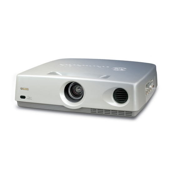
- Page 1 DPX–1 Digital Cinema Projector Projecteur Cinema Numerique OWNER’S MANUAL MODE D’EMPLOI...
-
Page 2: Important Safety Instructions
IMPORTANT SAFETY INSTRUCTIONS CAUTION RISK OF ELECTRIC SHOCK DO NOT OPEN CAUTION: TO REDUCE THE RISK OF ELECTRIC SHOCK, DO NOT REMOVE COVER (OR BACK). NO USER-SERVICEABLE PARTS INSIDE. REFER SERVICING TO QUALIFIED SERVICE PERSONNEL. • Explanation of Graphical Symbols The lightning flash with arrowhead symbol, within an equilateral triangle, is intended to alert you to the presence of uninsulated “dangerous... - Page 3 We Want You Listening For A Lifetime YAMAHA and the Electronic Industries Association’s Consumer Electronics Group want you to get the most out of your equipment by playing it at a safe level. One that lets the sound come through loud and clear without annoying blaring or distortion –...
- Page 4 YAMAHA will not be held responsible for any damage resulting from use of this unit with a voltage other than that specified.
-
Page 5: Inappropriate Places For Installation
Inappropriate places for installation If this unit is not correctly installed in an appropriate place, it may cause fire or failure, or damage to this unit may result. Carefully choose the place to install this unit by avoiding the places listed below. Places where the temperature and humidity vary greatly •... - Page 6 Memo...
-
Page 7: Table Of Contents
PRECAUTIONS Introduction Thank you for purchasing this YAMAHA product. We hope it will give you many years of trouble-free enjoyment. For the best performance, read this manual carefully. It will guide you in operating your YAMAHA product. Features • High-brightness and high-contrast images achieved by DLP™... -
Page 8: Controls And Functions
Controls and functions I Front panel and terminal panel Focus ring, zoom ring Focuses and zooms the lens Remote sensor Lens cap Terminal panel <side> S VIDEO 1 —5 INPUT A (BNC jacks) These jacks receive component video and RGB signals. Component video signals from an A/V component are sent to the 1—3 jacks. -
Page 9: Control Panel
I Control panel Control panel <on the rear> STANDBY/ON LAMP /COVER 2 3 4 5 6 7 indicator (P.14) 2 STANDBY/ON button (P.10) Secondary power button Turns on and sets this unit in the standby mode. This button is effective only when the primary power switch is turned on. Standby mode In this mode, this unit consumes a small amount of power to receive infrared siganls from the remote control. -
Page 10: Remote Control
Controls and functions I Remote control The corresponding buttons on the control panel and the remote control perform same functions. Use the remote control by aiming at the remote control sensor located on the front or back of this unit. The operation range is 50 degrees horizontally and 30 degrees vertically within a distance of 6 m (20 feet). -
Page 11: Installation
INSTALLATION How to install There are four ways this unit can be installed: installing on a tabletop in front of the screen, mounting on the ceiling in front of the screen, installing on a tabletop behind a semi-translucent screen, mounting on the ceiling behind a semi-translucent screen. It is necessary to set the installation method for “INSTALLATION”... -
Page 12: Screen Setting
How to install I Screen setting The screen height depends on your screen size. This unit projects facing slightly upward, although projecting symmetrically about the lens center on the horizontal axis. The following charts show the height [H] from the lens center to the screen bottom. Consider dimension [H] when determining the position to set your screen. -
Page 13: Installation Methods
I Installation methods 1. Installing on a tabletop Projection distance [L] See page 5. Floor Adjusters 2. Mounting on the ceiling A ceiling mount bracket (optional) is needed for mounting this unit on the ceiling. Consult with your local authorized dealer or any reliable contractor to mount this unit on the ceiling. -
Page 14: Connections
How to connect • Before making connections, make sure that the power of this unit and other components is turned off. • Some components require different connection methods and have different jack names. Refer to the operation instructions for each component to be connected to this unit. -
Page 15: Connecting A Computer
I Connecting a computer There are three types of terminals to connect this unit to a computer as listed below. Use the correct cables for the terminals to be connected. Input INPUT A INPUT B DVI cable (digital only) D-Sub monitor cable DVI output Monitor output terminal... -
Page 16: Basic Operation
Using this unit This section describes the basic projecting operation after installa- tion and connection have been completed. Detailed settings must be made for installation, screen, input signal and so on, by following the menu setting procedure described in the section starting on page 15. I Turning on the power Remove the lens cap before starting any operation of this unit. -
Page 17: Selecting The Input Source
I Selecting the input source Press the INPUT button to display the menu for input signals on the screen. Select the input terminal and the input signal to be projected by pressing the h or g button, and confirm the selection by pressing the SELECT button. -
Page 18: Selecting "Aspect
Using this unit I Selecting “ASPECT” “ASPECT” selects the most appropriate way of displaying the image on the screen for the six common types of signals listed below. Available parameters for “ASPECT” change depending on the “SCREEN ASPECT” setting. This unit has the “AUTO” mode which auto- matically detects the type of signals and changes the display aspect. - Page 19 G Available aspect modes when “SCREEN ASPECT” is set to “16:9” 1 AUTO When the input signal is in letterbox or squeeze, this mode detects it and automatically switches to the most appropriate mode. This mode is effective only when the signal is sent with information about its type.
-
Page 20: Turning Off This Unit
Using this unit I Turning off this unit When you have finished using this unit, press the STANDBY/ON button. There will be a message to confirm turning off this unit. Press the STANDBY/ON button again to turn off this unit. The lamp turns off and the indicator flashes in orange while the fan is rotating to cool the lamp for approximately two minutes. -
Page 21: Menu
MENU Menu structure It is necessary to make various settings on the menu so that this unit can achieve the best performance. The menu has a three-level hierarchy; menu group, menu item, and submenu for some menu items. Listed below are the four menu groups. 1 <IMAGE>... -
Page 22: Signal
Menu structure I 2 <SIGNAL> ... Adjustment cannot be made without any input signal. Input signal ASPECT Video/Component/RGB Sets the aspect ratio of displaying the image on the screen. “AUTO” automatically switches to the most appropriate mode. “NORMAL” (THROUGH) projects the image as the input signal is sent. - Page 23 I 3 <INITIAL> COLOR SYSTEM Selects the color system when the video signal is input among NTSC, NTSC PAL60, SECAM. AUTO should normally be selected so that the appropriate color system can be automatically selected depending on the input signal. INPUT A SIGNAL Selects the type of input signal sent to the INPUT A jacks.
-
Page 24: Menu Operation
Menu operation I Menu screen and operating buttons This section provides you with general information about the menu screen and operating buttons on the remote control and this unit’s control panel for easier operation. Please read it carefully before starting to operate the menu. MOVE MENU WINDOW MOVE MENU WINDOW IMAGE... -
Page 25: Basic Menu Operation
I Basic menu operation To ensure proper projection, start with setting and adjustment for the menu group “SETUP”. STANDBY/ON AUTO PATTERN PATT 1, 6 ESCAPE MENU 3, 5 SELECT 2, 4 ASPECT INPUT RESET STILL HIDE Press the MENU button to open the menu. The previous menu screen opens if menu operation has already been performed. -
Page 26: Submenu
Menu operation Some items are adjusted by increasing or decreasing the value on the scale, and others by selecting a number or a word. KEYSTONE KEYSTONE MODE NORMAL Press the RESET button to reset the parameter to the factory setting. (Items without a factory setting cannot be reset.) Press the h or g button to move the cursor to the next item. -
Page 27: Basic Submenu Operation
I Basic submenu operation [Operation groups A and B] Select the menu item to be adjusted by following steps 1—3 in “Basic menu operation”. The submenu mark “ ” appears on the right side of the item. IMAGE SIGNAL INITIAL COLOR SYSTEM AUTO INPUT A SIGNAL... - Page 28 Menu operation G Submenu operation—“WHITE BALANCE” [Operation group C] Select the menu item “WHITE BALANCE” in the menu group “IMAGE” by following steps 1—3 in “Basic menu operation”. The submenu mark “ ” appears on the right side of the item. IMAGE SIGNAL INITIAL...
- Page 29 Select “YES” by pressing the h or g button, and then press the SELECT button to reset the lamp running time to 0. IMAGE SIGNAL INITIAL PRESS ”SELECT” TO RESET LAMP RUNNING TIME ON ”YES”. LAMP RUNNING TIME 2H. ESCAPE: EXIT MEMORY1 Press the MENU button to close the menu.
-
Page 30: One-Touch Image Menu
Menu operation I One-touch image menu Press the SELECT button to open the one-touch image menu when the menu has not been opened. The image menu items appear at the bottom of the screen one after another. The previous parameter appears once menu operation has been performed. -
Page 31: Memory Function
Memory function This unit has a memory function that can store six settings to project different types of input sources in the most appropriate manner. Select one of these six settings that is most suitable for your projection. Although six settings have already been prepared, each parameter in the settings can be changed and restored as you wish. -
Page 32: Resetting To The Factory Setting
Memory function I Resetting to the factory setting For one parameter Select the parameter to be reset to the factory setting by following steps 1—3 in “Basic menu operation”. Press the RESET button on the remote control to reset to the factory setting. (Items without a factory setting cannot be reset.) For all parameters in the memory setting being selected... -
Page 33: Additional Information
ADDITIONAL INFORMATION Additional information I Glossary DLP™ technology This stands for Digital Light Processing. DLP uses the DMD™ optical semiconductor chip developed by Texas Instruments. Component video signal This signal is sent with its luminance signal and color signal independent. It creates higher image quality compared with an ordinary composite video signal because it bypasses the mixing and separating circuits. -
Page 34: Projectable Signals
Additional information I Projectable signals The following charts show the types and formats of the signals that can be projected by this unit. Any signals not listed below may not be properly projected. 1. TV format 1 ------ Composite or S video signals sent to the VIDEO or S VIDEO input terminal V active Type of signal (lines) -
Page 35: Menu Items And Input Signals
I Menu items and input signals A menu item can or cannot be adjusted depending on the type of input signal. The following list shows the types of input signals that can be adjusted for each item in the menu groups <IMAGE> and <SIGNAL>. Most of these items can store their settings in the memory (MEMORY 1–6). -
Page 36: Message Display
Additional information I Message display Message NO SIGNAL INPUT A <COMPONENT> (Example) OUT OF RANGE UNKNOWN FORMAT AUTO SYNC... STILL STILL OFF MEMORY 1—6 ESCAPE:EXIT (Example) LAMP REPLACEMENT TIME HAS COME. PLEASE REPLACE WITH A NEW LAMP. PRESS “ESCAPE” TO REMOVE THIS INDICATION. -
Page 37: Maintenance
Maintenance I Regular care Disconnect the power cable from this unit before starting regular care. Clean the housing of this unit with a soft cloth. If heavily soiled, use a damp cloth with a mild detergent and then wipe with a dry cloth again. -
Page 38: Replacing The Lamp Cartridge
Maintenance I Replacing the lamp cartridge The lamp used as the source of light is a consumable and will gradually lose its brightness over the course of usage. It is recommended that the lamp should be replaced when its usage exceeds 1000 hours in order to enjoy the best image possible. -
Page 39: Troubleshooting
Troubleshooting Problem This unit does not turn on. The power switch is not turned on. You attempted to turn on this unit again just after having turned off the power switch. The filter cover is not correctly attached. No picture The lamp cover is not correctly attached. -
Page 40: Specifications
Specifications I Specifications Optical Projection mode ... DLP™ (Digital Light Processing) Images of 1024 x 768 pixels, 0.9 inch Lens ... f=35 to 42 mm F=2.7 to 3.0 Lamp ... 120 W VIP lamp Image size ... 200 inches at maximum Projection distance 10.6 m (35 ft.) (wide image, 16:9 screen) Luminosity ... -
Page 41: Dimensional Drawing
I Dimensional drawing 3-1/8 3-9/16 16-5/8 RGB/YP S VIDEO VIDEO INPUT B TRIGGER OUT INPUT A D4 VIDEO RS-232C HD/SYNC 7-1/2 Specifications... - Page 42 YAMAHA ELECTRONIQUE FRANCE S.A. RUE AMBROISE CROIZAT BP70 CROISSY-BEAUBOURG 77312 MARNE-LA-VALLEE CEDEX02, FRANCE YAMAHA ELECTRONICS (UK) LTD. YAMAHA HOUSE, 200 RICKMANSWORTH ROAD WATFORD, HERTS WD1 7JS, ENGLAND YAMAHA SCANDINAVIA A.B. J A WETTERGRENS GATA 1, BOX 30053, 400 43 VÄSTRA FRÖLUNDA, SWEDEN Printed in Japan V707760 YAMAHA MUSIC AUSTRALIA PTY, LTD.