Table of Contents
Advertisement
Quick Links
Advertisement
Table of Contents

Related Manuals for Siemens Moore 353


Summary of Contents for Siemens Moore 353
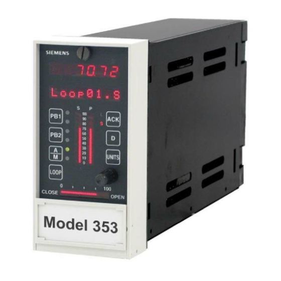
- Page 1 Siemens USER'S MANUAL Energy & Automation UM353-1 Rev. March 2003 Supersedes Rev. 10 4 2 . 4 5 T C2 0 5 3 . P UNITS LOOP CLOSE OPEN Moore 353 X03141S2 PROCESS AUTOMATION CONTROLLER...
-
Page 3: Table Of Contents
UM353-1 Contents TABLE OF CONTENTS SECTION AND TITLE PAGE PREFACE .................................. ix 1.0 INTRODUCTION ............................. 1-1 1.1 PRODUCT DESCRIPTION.......................... 1-2 1.2 FUNCTION BLOCKS ..........................1-4 1.2.1 LOOP Function Block Types........................ 1-4 1.2.2 Power Up Initialization ......................... 1-6 1.2.3 Configuration ............................1-6 1.3 PRODUCT SUPPORT .......................... - Page 4 Contents UM353-1 3.2.21 AWE_ - Analog Write Ethernet (V3.0) .................... 3-30 3.2.22 BATOT - Batch Totalizer ......................... 3-31 3.2.23 BATSW - Batch Switch ........................3-33 3.2.24 BIAS - Bias ............................3-34 3.2.25 CIE_- Coil Inputs - Ethernet (V3.0)....................3-35 3.2.26 CHR_ - Characterizer........................3-36 3.2.27 CMP_ - Comparator..........................
- Page 5 UM353-1 Contents 3.2.78 PID - PID Controller ......................... 3-83 3.2.79 PIDAG - PIDAG Controller ......................3-85 3.2.80 PRSEQ - Program Sequencer......................3-87 3.2.81 QHD_ - Quickset Hold ........................3-89 3.2.82 RATIO - Ratio ..........................3-90 3.2.83 RCT_ - Repeat Cycle Timer......................3-91 3.2.84 RLM_ - Rate Limiter (V3.0) ......................
- Page 6 Contents UM353-1 7.2.2 Station String Data (8-bit ASCII Char - 2/Word) ................. 7-5 7.2.3 Station Coil Data (1-bit)........................7-5 7.2.4 Station Status Word (SSW)........................7-5 7.3 LOOP DATA..............................7-6 7.3.1 Dynamic Loop Integer Data........................7-7 7.3.2 Variable Loop Integer Data........................7-8 7.3.3 Static Loop Integer Data ........................
- Page 7 UM353-1 Contents 10.1.6 Alarms............................... 10-4 10.1.7 TAG ..............................10-5 10.1.8 QUICK.............................. 10-5 10.1.9 TUNE..............................10-6 10.1.10 View mode ............................10-7 10.2 SYSTEM CHECKOUT..........................10-7 11.0 MAINTENANCE ............................11-1 11.1 TOOLS AND TEST EQUIPMENT ......................11-1 11.2 PREVENTIVE MAINTENANCE ......................11-2 11.2.1 Environmental Considerations ......................
- Page 8 8-22 LIL Network Wiring............................. 8-21 8-23 LonWorks Network Wiring.......................... 8-22 8-24 Modbus Communications, Personal Computer to Moore 353 or Moore 354..........8-23 8-25 Moore 353 to Model 363 VIEWPAC Analog Input Wiring ................ 8-24 8-26 Controller Power Wiring ..........................8-24 8-27 Suggested Power Wiring ..........................
- Page 9 11.1 RTC/CB and RCB Boards, Off-Line Error Codes..................11-9 11.2 On-Line Error and Status Codes......................... 11-10 14.1 Moore 353 Model Designation ........................12-2 Changes for Revision 11, March 2003 Significant changes for Rev 11 are indicated by change bars in the outside page margins. Some of these changes are listed below.
- Page 10 Automation, Inc. Other trademarks are the property of their respective owners. Siemens Energy & Automation, Inc. assumes no liability for errors or omissions in this document or for the application and use of information included in this document. The information herein is subject to change without notice.
-
Page 11: Preface
Conventions and Usage Notes: • In this User’s Manual, a Moore 353 can be referred to using the term Moore 353, Model 353, or simply 353. The terms controller and station are also used to prevent repetition. •... - Page 12 The contents of this manual shall not become part of or modify any prior or existing agreement, commitment or relationship. The sales contract contains the entire obligation of Siemens. The warranty contained in the contract between the parties is the sole warranty of Siemens. Any statements continued herein do not create new warranties or modify the existing warranty.
- Page 13 A properly grounded conductive wrist strap must be worn whenever an electronics module or circuit board is handled or touched. A service kit with a wrist strap and static dissipative mat is available from Siemens (PN15545-110). Equivalent kits are available from both mail order and local electronic supply companies.
- Page 14 Contents UM353-1 March 2003...
-
Page 15: Introduction
Introduction 1.0 INTRODUCTION This User’s Manual contains configuration, installation and service information for the Moore 353 Process Automation Controller. It is divided into fifteen sections. • Section 1, Introduction, has general information about the organization of this manual, the controller, product support, and the contents of a typical shipment. -
Page 16: Product Description
An exploded view of the controller appears in Figure 1-1. At the heart of the Moore 353 is a powerful MPU Controller board that uses the latest in microprocessor technology. It includes on-board I/O and reusable function blocks, and it is capable of solving a vast array of control implementations including single loop, cascade, and dual loop. - Page 17 Although the Moore 353 can be connected to and operated entirely from a central operator workstation, such as i|station, a controller faceplate is included. This local operator interface is for applications where loops need individual attention during startup, troubleshooting, maintenance, or emergency conditions.
-
Page 18: Function Blocks
A number of loops can be configured in the Moore 353 and a number of function block types are available as described in the sections that follow. - Page 19 UM353-1 Introduction Fixed Loop Function Blocks can be selected for use within each configured LOOP and include those blocks which define the major functions of a loop. The operator display function block (e.g. ODC Operator Display for Controllers) defines the loop type, the function of ESN = 000 the local faceplate as well as the processing of commands coming from a Process...
-
Page 20: Power Up Initialization
Three power up modes (hot, warm, and cold) are utilized in the Moore 353 that affect the initialization of function blocks. These modes are configured by two power up timers (warm and cold), included in STATION parameters. The station will initialize a hot start when power up occurs prior to the expiration of the warm timer. -
Page 21: Equipment Delivery And Handling
If it is found that some items have been damaged or are missing, notify the Process Instrumentation Division of Siemens Energy and Automation immediately and provide full details. In addition, damages must be reported to the carrier with a request for their on-site inspection of the damaged item and its shipping carton. -
Page 22: Typical Shipment Contents
Contents: 2 Mounting Clips and 2, 8-32 x 1 Screws (see the Parts List at back of this manual for part numbers) 4. I/O Expander Board Kits PN16353-52 I/O Expander Board Kit - The I/O Expander Board is factory installed when a Moore 353 with Expansion Board option 1 is ordered. - Page 23 4-20 mA to 15-75 mV Range Resistor, 3.75Ω, 0.1%, 3W, WW Sleeving Crimp-On Connector TC Reference Junction, 100Ω Kit Installation Instruction 5. UM353-1, Moore 353 User’s Manual (this manual), qty. 1 6. Additional items as required by your order. Refer to the packing list accompanying a shipment. March 2003...
- Page 24 Introduction UM353-1 1-10 March 2003...
-
Page 25: Configuration Overview
UM353-1 Configuration Overview 2.0 CONFIGURATION OVERVIEW Configuration enables a user to select function blocks, stored in the controller, from an available list and enter appropriate block parameters to implement a specific control strategy. Although configuration affects the entire station, the controller partitions related control implementations into LOOPS. A maximum of 99 loops can be configured and 25 can have operator displays that are mapped to network communications Each LOOP can contain the function blocks listed in the following paragraphs. -
Page 26: Lil Global Data I/O Function Blocks
Configuration Overview UM353-1 on the local faceplate when that loop is selected and also how loop data will be mapped on the Modbus or LIL network interface. Each LOOP can have one controller function block (i.e. ID, ONOFF, PD, PID, or PIDAG). A/M ....Auto/Manual ODC ....Operator Display for Controllers ACS01-99...ARCCosine (V1.3) -
Page 27: Ethernet Data I/O Function Blocks
UM353-1 Configuration Overview 2.5 ETHERNET DATA I/O FUNCTION BLOCKS These function blocks are available in the quantities indicated within a controller when the optional Ethernet Network board is installed. These blocks can be selected for use within individual loops but block names are unique station wide. - Page 28 Configuration Overview UM353-1 A configuration is designed by first arranging the needed function blocks in a fashion similar to that of a PI & D drawing. Parameter and calibration values are determined next and then entered on a Configuration Documentation Form or into the Graphical Configuration software.
-
Page 29: Operation During Local On-Line Configuration
UM353-1 Configuration Overview • Calibration can also be performed within individual loops containing the input or output function blocks used in the LOOP. • At the LOOP level, new loops can be added, loops can be deleted, or an existing loop can be edited. When a new loop is created, the controller will assign a default name (e.g. - Page 30 Configuration Overview UM353-1 ENTER EXIT CONF LOOP <> STATION SECURITY CLOCK STA TN <> <> ETHERNET FCO LIB <> <> <> <+> <+> <+> LEV1 COM AIN1 SET TIME <+> <+> IP ADRES CAL ZERO <+> 000000 PAC 353 11:00 CAL ZERO STORE STORE...
-
Page 31: Function Blocks
UM353-1 Function Blocks 3.0 FUNCTION BLOCKS This section contains a detailed description of each function block (FB) available for configuration . Each function block description is supplemented by: (1) a drawing of the block showing data inputs and outputs and control lines, (2) a block parameter table. - Page 32 Function Blocks UM353-1 Some users may prefer to use normalized 0-1 analog inputs for math calculations and scale outputs for display only; in this case, the Scaler function block may be used to provide an output range (OR) for the ODC (Operator display block).
-
Page 33: Station Function Blocks
UM353-1 Function Blocks 3.1 STATION FUNCTION BLOCKS Station function blocks include factory configured options (FCOs), security, and station parameters. Each is described in the following subsections. 3.1.1 FCO LIB - Factory Configuration Library The FCO LIB function block provides a selection of pre- configured applications. - Page 34 If a combination is lost, contact Siemens technical support to obtain a method to enter configuration and change the security codes. Refer to Section 1.3 for the contact information.
-
Page 35: Statn - Station Parameters
UM353-1 Function Blocks 3.1.3 STATN - Station Parameters The STATN function block enables entry of station STATION PARAMETERS identification and other station related information. When the station is networked using Modbus or the LIL option board the address is used by higher level devices STATN to obtain information from the station. - Page 36 Function Blocks UM353-1 at a Moore 352Plus or Moore 353 Display Assembly’s MMJ-11 connector, or a Moore 354 or 354N Controllers’ DB9 display/configuration port, is RS232 and uses an address of 1. The Cycle Time of the station can be viewed as a parameter within the STATN block. In addition, a bias can be added to increase the total cycle time of the station.
-
Page 37: Clock - Real Time Clock (V2.0/2.2)
UM353-1 Function Blocks 3.1.4 CLOCK - Real Time Clock (V2.0/2.2) The CLOCK function block is available when the RTC/CB (Real Time Clock / Configuration Backup) option board is installed in the controller and the controller includes firmware version V2.0 or higher. This function block enables the current time and date to REAL TIME CLOCK be viewed when using the local faceplate. -
Page 38: I/O And Loop Function Blocks
Function Blocks UM353-1 3.2 I/O AND LOOP FUNCTION BLOCKS This section provides a detailed description of each input/output and loop function block. Blocks are listed alphabetically. 3.2.1 A/M - A/M Transfer One A/M function block can be used per loop and it is A/M TRANSFER normally used on the output of controller blocks to enable auto/manual operation of the loop. - Page 39 UM353-1 Function Blocks EMERgency MANual will be asserted when input EM is high (1). This causes the output to hold at the last position and permits the operator to adjust the manual value under the conditions listed for MANual. It will also assert an EM MAN status, at the configured priority, to the operator display.
-
Page 40: Acs - Arccosine
Function Blocks UM353-1 3.2.2 ACS - ARCCOSINE ACS_ function blocks, in firmware 1.30 and higher, accept an input between -1.0 and 1.0. Each provides an output signal in ARCCOSINE radians of which the input is the cosine. ESN = 000 Input X Output 1 = ACOS (X) -
Page 41: Ag3 - Aga 3 Orifice Metering Of Natural Gas
UM353-1 Function Blocks 3.2.4 AG3 - AGA 3 Orifice Metering of Natural Gas AG3 function blocks, which can be used on a one per loop basis, are available in firmware 1.30 and higher, This block AGA 3 uses the AGA 3 (American Gas Association Report #3) calculation to accurately measure the flow of natural gas using ESN = 000 an orifice meter with flanged taps. - Page 42 Function Blocks UM353-1 = real gas relative density (specific gravity) = compressibility at standard conditions = compressibility at flowing conditions at upstream tap - = compressibility at base conditions The specific gravity factor ( ) and the compressibility factors ( ) can be entered manually using HLD (Hold) function blocks, computed, and then downloaded from a host device, or calculated in the controller using the AG8 (AGA 8 Compressibility Factors of Natural Gas) function block.
-
Page 43: Ag7 - Aga 7 Measurement Of Gas By Turbine Meters
UM353-1 Function Blocks 3.2.5 AG7 - AGA 7 Measurement of Gas by Turbine Meters AG7 function blocks, which can be used on a one per loop basis, are available in firmware 1.30 and higher, This block AGA 7 uses the AGA 7 (American Gas Association Report #7) calculation to accurately measure the volume flow of gas at ESN = 000 base conditions using a turbine meter. -
Page 44: Ag8 - Aga 8 Compressibility Factors Of Natural Gas
Function Blocks UM353-1 3.2.6 AG8 - AGA 8 Compressibility Factors of Natural Gas AG8 function blocks, which can be used on a one per AGA 8 loop basis, are available in firmware 1.30 and higher. This block calculates the compressibility factors of natural gas ESN = 000 in accordance with AGA 8 Report No. -
Page 45: Aie_ - Analog Input - Ethernet (V3.0)
Ethernet if the device has the scaling information packaged with the data. This is a feature provided by AOE function blocks from other Siemens MOORE controllers. AOE blocks are defined by using the Modbus Registers from table 3 below. If this feature is not available, the default setting of the RANGE parameter "MAN"... - Page 46 Function Blocks UM353-1 TABLE 1 Floating Point Number Formats BYTE ORD Type Description Byte Order Comments Big Endian FP Format 4, 3,2, 1 Standard Usage Big Endian FP w/ bytes swapped 3, 4, 1, 2 Little Endian FP Format 1, 2, 3, 4 Little Endian FP w/ bytes swapped 2, 1, 4, 3 TABLE 2 Integer Default Values...
-
Page 47: Ail_ - Analog Input - Lil
UM353-1 Function Blocks 3.2.8 AIL_ - Analog Input - LIL AIL_ function blocks are available when the optional LIL communication board is installed. They allow the ANALOG INPUT - LIL controller to obtain global data from other stations on the LIL. -
Page 48: Ain_ - Analog Inputs
Function Blocks UM353-1 3.2.9 AIN_ - Analog Inputs AIN_ function blocks convert a voltage input, having a ANALOG INPUT _ range defined during calibration, into a block output signal that is scaled in engineering units. The output is then interconnected to other function blocks within the AIN_ Output Range AIN_+... -
Page 49: Ainu_ - Analog Inputs, Universal
UM353-1 Function Blocks 3.2.10 AINU_ - Analog Inputs, Universal AINU_ function blocks are available on the optional I/O ANALOG INPUT- UNIVERSAL_ Expander Board. These function blocks convert sensor inputs such as T/C (thermocouple), RTD (resistance temperature AINU_ detector), millivolt, ohm, and slidewire sources into block AINU_a Output Range ANALOG INPUT... - Page 50 Function Blocks UM353-1 TABLE 3.4 Input Types ENGineering UNITS AVAILABLE ON INPUT TYPES Deg C (degrees Celsius) JT/C, KT/C, TT/C, ET/C, ST/C, RT/C, BT/C, NT/C, DRTD, URTD, JRTD Deg F (degrees Fahrenheit) JT/C, KT/C, TT/C, ET/C, ST/C, RT/C, BT/C, NT/C, DRTD, URTD, JRTD Deg R (degrees Rankine) JT/C, KT/C, TT/C, ET/C, ST/C, RT/C, BT/C, NT/C, DRTD, URTD, JRTD JT/C, KT/C, TT/C, ET/C, ST/C, RT/C, BT/C, NT/C, DRTD, URTD, JRTD...
-
Page 51: Aip_ - Analog Input Lev_Percent
UM353-1 Function Blocks 3.2.11 AIP_ - Analog Input lev_Percent AIP_ function blocks convert an analog signal with a lev-percent type SNVT (Standard Network ANALOG INPUT LEV_PERCENT Variable Type) received from the LonWorks network into a block output, scaled in engineering units, for interconnection to other function blocks LONWorks within the controller. -
Page 52: Alarm - Alarm
Function Blocks UM353-1 3.2.12 ALARM - Alarm ALARM function blocks can be used on a one per loop basis ALARM and contain four (4) alarms associated with Input P (normally the process input to the controller function block). Each alarm ESN = 000 ALARM Alarm 1 Status... - Page 53 UM353-1 Function Blocks Alarm Types HI compares the process input with the limit setting and it will trip the alarm status high (1) when the Alarm Status LIMIT process is equal to or higher than the limit setting. The Input P alarm status will clear (0) when the process is less than the limit setting minus the deadband.
-
Page 54: And_ - And Logic
Function Blocks UM353-1 An alarm status word is shown below. A_=1 when the alarm is active N_=1 when the alarm is Not acknowledged E_=1 when the alarm is enabled (when the alarm is disabled the E, N, and A bits are set to 0) OS=1 indicates that all alarms are identified as Out of Service which means that all alarms function normally but the OS flag indicates to a higher level device that they can be ignored. -
Page 55: Aoe_ - Analog Output- Ethernet (V2.4)
UM353-1 Function Blocks 3.2.14 AOE_ - Analog Output- Ethernet (V2.4) AOE_ function blocks are available when the optional ANALOG OUTPUT - ETHERNET Ethernet communication board is installed. Up to 32 AOE blocks are available and are assigned in sequence with each use, station wide. -
Page 56: Aop_ - Analog Output Lev_Percent
Function Blocks UM353-1 3.2.16 AOP_ - Analog Output lev_Percent AOP_ function blocks convert a function block interconnection signal, input S, to a output which is ANALOG OUTPUT LEV_PERCENT bound to a network variable in a node on the LonWorks network having a SNVT (Standard AOP_ Network Variable Type of lev_percent. -
Page 57: Aout_ - Analog Outputs
UM353-1 Function Blocks 3.2.17 AOUT_ - Analog Outputs AOUT_ function blocks convert function block interconnection signals, connected to input S, to a ANALOG OUTPUT _ block output having a range of 4-20 mAdc. Input D can be used to disconnect the output from the AOUT_ load when asserted high (1). -
Page 58: Asn_ - Arcsine
Function Blocks UM353-1 3.2.18 ASN_ - ARCSINE ASN__ function blocks, in firmware 1.30 and higher, accept an input between -1.0 and 1.0 and provide an output signal in radians of ARCSINE which the input is the sine. ESN = 000 Input X Output 1 = ASIN (X) - Page 59 UM353-1 Function Blocks 3.2.20 ATN_ - ARCTANGENT ATN__ function blocks, in firmware 1.30 and higher, output a signal in radians of which the input is the tangent. ARCTANGENT ESN = 000 Input X Output 1 = ATAN (X) ATAN (X) Output 1 Input X INPUT X ....
-
Page 60: Awe_ - Analog Write Ethernet (V3.0)
Modbus address to be configured. When connecting to MAX INT 65535 Uint other Siemens MOORE controllers the Modbus address is set to MIN INT -32768 Sint 1. In some cases, other devices may use a different address or... -
Page 61: Batot - Batch Totalizer
UM353-1 Function Blocks 3.2.22 BATOT - Batch Totalizer BATOT function blocks can be used on a one per loop BATCH TOTALIZER basis and integrate an analog input. Each provides an BATOT ESN = 000 output signal representing a total integrated value over the otaL Ext. - Page 62 Function Blocks UM353-1 output requirement is less than the maximum pulse rate of 5/sec available with a 0.1 sec cycle time. The requirement would also be satisfied if a PUL SCAL of 1 was selected which would have required a maximum pulse rate of 1/sec.
-
Page 63: Batsw - Batch Switch
UM353-1 Function Blocks 3.2.23 BATSW - Batch Switch BATSW function blocks can be used on a one per loop basis. Each is used with a PID function block to eliminate BATCH SWITCH overshoot during startup conditions. When placed in the feedback path of the controller it causes the reset ESN = 000 BATSW... -
Page 64: Bias - Bias
Function Blocks UM353-1 3.2.24 BIAS - Bias BIAS function blocks can be used on a one per loop basis BIAS and provide a means to bias a signal, such as the setpoint in an external set application. Inputs A and E (external bias) BIAS ESN = 000 are summed and then added to the operator adjustable bias... -
Page 65: Cie_- Coil Inputs - Ethernet (V3.0)
T A R START ing CoiL .. 0000 - 65535 (null) Siemens MOORE controllers, the Modbus NO. OF C oiLs ....1 - 16 address is set to 1. In some cases, other Modbus devices may use a different address or when going through a Modbus TCP/IP gateway a Modbus network may have multiple devices, each having a unique address. -
Page 66: Chr_ - Characterizer
Function Blocks UM353-1 3.2.26 CHR_ - Characterizer CHR_ function blocks provide 10 segments that can be used to characterize the X input signal. Individual CHARACTERIZER segments are configured by entering the Xn, Yn and Xn+1, Yn+1 points for each segment. All Xn+1 points must be CHR_ ESN = 000 greater than the associated Xn points. - Page 67 When connecting to I N P U T INPUT 6 ....loop tag.block tag.output (null) other Siemens MOORE controllers, the Modbus I N P U T INPUT 7 ....loop tag.block tag.output (null) I N P U T INPUT 8 ....
- Page 68 Function Blocks UM353-1 1. oncE will write once to the START CL (Modbus Starting Coil. The controller will write when any block input value changes state. 2. P2P will update at the controller peer to peer rate set in the ETHERNET block. 3.
-
Page 69: Did_ - Digital Input Lev_Discrete
UM353-1 Function Blocks 3.2.31 DID_ - Digital Input lev_Discrete DID_ function blocks convert 16 on/off signals received from DIGITAL INPUT LEV_DISCRETE a single or multiple nodes on the LonWorks network into 16 block outputs for use by other function blocks within the controller. -
Page 70: Die_ - Digital Input - Ethernet (V3.0)
Both are treated the same in most Modbus devices but the Input type is the most common usage. The use of DOE blocks in other Siemens MOORE controllers as the input source is defined by using the Modbus Registers from the table below. -
Page 71: Dil_ - Discrete Input
UM353-1 Function Blocks 3.2.33 DIL_ - Discrete Input _ LIL DIL_ function blocks are available when the optional LIL communication board is installed. DIL block numbers are DISCRETE (WORD) INPUT - LIL assigned in sequence with each use, station wide. The block allows the station to obtain a global word (GW) from another DIL_ station on the LIL. -
Page 72: Din_ - Digital Inputs
Function Blocks UM353-1 3.2.34 DIN_ - Digital Inputs DIN_ function blocks can be used to sense a discrete signal from an external source and provide a block output DIGITAL INPUT _ representing the state of this signal. Blocks are available on the Controller Board and on the Expander Board. -
Page 73: Dinu_- Digital Inputs, Universal
UM353-1 Function Blocks 3.2.35 DINU_- Digital Inputs, Universal DINU_ blocks have multi-function capability: DIGITAL INPUT - UNIVERSAL • sensing a discrete input and providing a high (1) or low (0) output representing the state of the input DINU_ • totalizing and scaling the count of input pulses Output Range Reset DIGITAL INPUT... - Page 74 Function Blocks UM353-1 3.2.36 DIS_ - Digital Input _ State DIS_ function blocks, in firmware 1.30 and higher, convert a 16- DIGITAL INPUT _ STATE bit word received from a single node on the LonWorks network into 16 block outputs for interconnection to other function blocks within the controller.
-
Page 75: Div_ - Division
UM353-1 Function Blocks 3.2.37 DIV_ - Division DIV_ function blocks perform simple arithmetic division. The output will be the quotient of the two configured DIVISION inputs N/D. The output will be limited to the maximum real number and, if the divisor is 0.0, the output will go to DIV_ ESN = 000 the maximum real number with the sign determined by the... -
Page 76: Dod_ - Digital Output Lev_Discrete
Function Blocks UM353-1 3.2.39 DOD_ - Digital Output lev_Discrete DOD_ function blocks transmit up to 16 on/off signals DIGITAL OUTPUT LEV_DISCRETE received from a controller block interconnection to remote nodes on the LonWorks network. A maximum of 6 DOD blocks can be used, up to the limit of nodes allowed on the Lon network or the memory limit of the controller. -
Page 77: Doe_ - Digital Output - Ethernet (V2.4)
UM353-1 Function Blocks 3.2.40 DOE_ - Digital Output - Ethernet (V2.4) DOE_ function blocks are available when the optional DIGITAL OUTPUT - ETHERNET Ethernet communication board is installed. Up to 32 DOE blocks are available and are assigned in sequence with each use, station wide. -
Page 78: Dos
Function Blocks UM353-1 3.2.42 DOS__ - Digital Output State DOS_ function blocks, in firmware 1.30 and higher, transmit up DIGITAL OUTPUT _ STATE to 16 on/off signals received from a controller block interconnection to a remote node on the LonWorks network as a single 16-bit word value. -
Page 79: Dout_ - Digital Outputs
UM353-1 Function Blocks 3.2.43 DOUT_ - Digital Outputs DOUT_ function blocks are used to turn on remote devices powered from an external source. The negative DIGITAL OUTPUT _ terminal of the external power source must be connected to station common. The transistor switch will turn on when DOUT_ the block input S is high (1) and will turn off when low DOUT_+... -
Page 80: Dtm_ - Dead Time Table
Function Blocks UM353-1 3.2.44 DTM_ - Dead Time Table DTM_ function blocks provide shift registers to hold the DEAD TIME analog input signal A for a period of time and shift it from register to register to provide an overall delay between DTM_ ESN = 000 input and output as configured in parameter DEADTIME. -
Page 81: Dwe_ - Digital Write Ethernet (V3.0)
INPUT 2 ....loop tag.block tag.output (null) I N P U T INPUT 3 ....loop tag.block tag.output configured. When connecting to other Siemens (null) I N P U T INPUT 4 ....loop tag.block tag.output (null) MOORE controllers the Modbus address is set to 1. -
Page 82: Dyt_ - Delay Timer
Function Blocks UM353-1 3.2.46 DYT_ - Delay Timer DYT_ function blocks perform either an ON or OFF output delay as determined by the TYPE configuration DELAY TIMER parameter. ESN = 000 DYT_ ON Delay - When input P is low (0), output O1 is low. Elapsed Time If P goes high (1), the elapsed timer starts and sets O1 Remaining Time... -
Page 83: E/I - External/Internal Transfer Switch
UM353-1 Function Blocks 3.2.47 E/I - External/Internal Transfer Switch E/I function blocks can be used on a one per loop basis to select an analog signal, connected to input E E/I TRANSFER SWITCH (External) or input I (Internal), as a setpoint for the loop controller. -
Page 84: Esl - Events Sequence Logger
Function Blocks UM353-1 3.2.48 ESL - Events Sequence Logger ESL function blocks, in firmware 1.30 and higher, can be used on a one per loop basis to log events within the loop. EVENTS SEQUENCE LOGGER Each ESL input can be assigned a user tag (up to 8 ASCII characters) that will be displayed when viewing the logged events from the front panel. -
Page 85: Exp_ - Natural Exponentiation
UM353-1 Function Blocks 3.2.49 EXP_ - NATURAL EXPONENTIATION EXP_ function blocks, in firmware 1.30 and higher, perform the natural exponentiation function, base “e”. The output will be the NATURAL EXPONENTIATION value “e” raised to the power of input X. ESN = 000 Input X Output 1 Output 1... -
Page 86: Ftg_ - Falling Edge Trigger
Function Blocks UM353-1 3.2.51 FTG_ - Falling Edge Trigger FTG_ function blocks provide a high (1) output for one FALLING EDGE TRIGGER scan cycle each time input P transitions from a high (1) input to a low (0) input. FTG_ ESN = 000 FALLING EDGE Pulse Input... -
Page 87: Id - Id Controller
UM353-1 Function Blocks 3.2.54 ID - ID Controller ID is an integral only controller and one of five controller types that can be used on a one per loop basis. It uses ID CONTROLLER external feedback to provide integral action and, therefore, allows interaction with other function blocks or external ESN = 000 devices, such as pneumatic controllers and shutoff... -
Page 88: Ll_ - Lead/Lag
Function Blocks UM353-1 3.2.55 LL_ - Lead/Lag LL_ function blocks provide both lead and lag functions. LEAD/LAG The block can function as lag only by setting the TLEAD time to 0.0. The lag function is always active and has a ESN = 000 minimum setting of 0.01 minutes. -
Page 89: Ln_ - Natural Logarithm
UM353-1 Function Blocks 3.2.57 LN_ - NATURAL LOGARITHM NATURAL LOGARITHM LN_ function blocks, in firmware 1.30 and higher, will output the natural logarithm of input X. When the input is <= 0.0, the input will ESN = 000 be treated as the smallest number greater than 0.0 (i.e. 1.17..e-38) and Input X Output 1 =LNe (X) -
Page 90: Mth_ - Math
Function Blocks UM353-1 3.2.59 MTH_ - Math MTH_ function blocks provide universal arithmetic MATH capability. As shown in the block diagram, each input has MTH_ ESN = 000 gain and bias scaling. The resulting signals are then applied to configurable math operations (DIV, MUL, ADD and Input A SUB). -
Page 91: Mul_ - Multiplication
UM353-1 Function Blocks 3.2.60 MUL_ - Multiplication MUL_ function blocks perform arithmetic multiplication on MULTIPLICATION the three input signals. Any unused input will be set to 1.0 and will therefore have no affect on the output. MUL_ ESN = 000 Input A MULTIPLICATION Output 1... -
Page 92: Nor_ - Nor Logic
Function Blocks UM353-1 3.2.62 NOR_ - NOR Logic NOR_ function blocks perform a logical NOR on the three inputs. Any unused input will be set low (0). NOR_ ESN = 000 Input A Output 1 Input B Input C NOR TRUTH TABLE Output 1 INPUT A .. -
Page 93: Oda - Operator Display For Analog Indication & Alarming (V2.2)
UM353-1 Function Blocks 3.2.64 ODA - Operator Display for Analog indication & alarming (V2.2) ODA blocks are one of five operator displays that are used on a one per loop basis to configure the local operator display functions and Operator Display for Analog indication & alarming network parameters. - Page 94 Function Blocks UM353-1 Alarms have priorities 1 to 5, with 1 the highest. Alarms are reported to the operator faceplate in order of priority first and then in order of occurrence. Priority 1 causes the station bargraphs and condition (e.g. A1 HI) to flash and requires acknowledgment to stop flashing.
-
Page 95: Odc - Operator Display For Controllers
UM353-1 Function Blocks 3.2.65 ODC - Operator Display for Controllers ODC blocks are one of five operator displays that are used on OPERATOR DISPLAY for CONTROLLERS a one per loop basis to configure the local operator display functions and network parameters from a remote operator Process Range workstation associated with the loop. - Page 96 Function Blocks UM353-1 Communications’ section. The ‘LOOP #’ and ‘LIL CHAN’ parameters enable configuration of a loop index number (x) for Modbus data or a starting channel (n) for LIL loop data. Input CL controls local arbitration of changes to loop data from the network. When input CL is not configured, the three status outputs LO (in 1.21 firmware this output was named L), CN, and CM will be set high (1) and changes can be made from a network command or the local faceplate.
-
Page 97: Odd - Operator Display For Discrete Indication & Control (V2.2)
UM353-1 Function Blocks 3.2.66 ODD - Operator Display for Discrete indication & control (V2.2) ODD function blocks are one of five operator displays that can be used on a one per loop basis to configure the local Operator Display for Discrete indication & control operator display functions as well as network parameters. - Page 98 Function Blocks UM353-1 DigDisp1 O F F SV-103 Manual SV-206 Manual Block Diagram i|ware PC Faceplate Display 3-68 March 2003...
-
Page 99: Odp - Operator Display For Pushbuttons (V2.2)
UM353-1 Function Blocks 3.2.67 ODP - Operator Display for PushButtons (V2.2) ODP function blocks are one of five operator displays that can be used on a one per loop basis to configure local Operator Display for Pushbuttons operator display functions as well as network parameters. See the i|ware PC faceplate example on the next page. - Page 100 Function Blocks UM353-1 Group 1 Message START MS1036 STOP AUTO Feedback Messages STOP Groups 2 to 7 Group 8 Message START MS1036 STOP AUTO Feedback Messages STOP Note: Numbers shown on input lines indicate values of unconfigured inputs Block Diagram i|ware PC Faceplate Display 3-70 March 2003...
-
Page 101: Ods - Operator Display For Sequencer
UM353-1 Function Blocks 3.2.68 ODS - Operator Display for Sequencer ODS function blocks are one of five operator displays OPERATOR DISPLAY for SEQUENCER available on a one per loop basis to configure the local operator display functions as well as the network commands from an operator workstation associated with the loop. - Page 102 Function Blocks UM353-1 LIL parameter will contain the LIL starting Chan (n) location. . The LOOP# must be entered to enable either LIL or Modbus communications. An operator display must be configured in order to properly map station loop data to network data. Sequencer loop network data is mapped onto registers or coils when the standard Modbus interface is used and to channels/parameters when the optional LIL interface has been added.
-
Page 103: On/Off - On/Off Controller
UM353-1 Function Blocks 3.2.69 ON/OFF - On/Off Controller ON/OFF is an on/off controller with deviation function. It is one of five controller types that can be used on a one per ON_OFF CONTROLLER loop basis. ONOFF ESN = 000 When P-S (Process - Setpoint) reaches the HDEV limit, the Absolute Error Range Boolean output HO will go high (1) and when S-P (Setpoint... -
Page 104: Orsl - Override Selector
Function Blocks UM353-1 3.2.70 OR_ - OR Logic OR_ function blocks perform a logical OR on the three inputs. Any unused input will be set low (0). ESN = 000 Input A Output 1 Input B Input C OR TRUTH TABLE Output 1 INPUT A .. -
Page 105: Ost_ - One Shot Timer
UM353-1 Function Blocks 3.2.72 OST_ - One Shot Timer OST_ function blocks provide a high (1) output for a ONE SHOT TIMER predetermined time, set by ON TIME, when input P goes high (1). If input P goes low (0), the output will remain high until the time expires. -
Page 106: Pb1Sw - Pb1 Switch
Function Blocks UM353-1 3.2.73 PB1SW - PB1 Switch PB1SW is one of three general purpose switches available PB1 SWITCH in each loop. It can be utilized for switching Boolean signals in such applications as: toggling Console/Local operation of the ODC or ODS function blocks, Start/Stop, PB1SW ESN = 000 controlling the position of a TSW (Transfer Switch) -
Page 107: Pb2Sw - Pb2 Switch
UM353-1 Function Blocks 3.2.74 PB2SW - PB2 Switch PB2SW is one of three general purpose switches PB2 SWITCH available in each loop. It can be utilized for switching Boolean signals in such applications as: toggling the EITS (External/Internal setpoint Transfer Switch) ESN = 000 PB2SW function block, Start/Stop, controlling the position of a... -
Page 108: Pb3Sw - Pb3 Switch
Function Blocks UM353-1 3.2.75 PB3SW - PB3 Switch PB3SW is one of three general purpose switches, PB3 SWITCH available in each loop. It can be utilized for switching Boolean signals in such applications as: Start/Stop, controlling the position of a TSW (Transfer Switch) PB3SW ESN = 000 function block for switching analog signals, or other... -
Page 109: Pcom - Phase Communication
UM353-1 Function Blocks 3.2.76 PCOM - Phase COMmunication The Phase Communication PCOM function block, in firmware 1.30 and higher, is available on a one per loop Phase COMunication basis to enable communication with a higher level device, such as a PC running a batch management PCOM software program. - Page 110 Function Blocks UM353-1 EMERG R 1/0 (unconfigured = 0) READY INTRLK R 1/0 R 1/0 INIT_OK (unconfigured = 1) FAILED R 1/0 R 1/0 DFAIL (unconfigured = 0) DONE RESET ABORTED READY READY R 1/0 (unconfigured = 1) READY READY READY START READY...
-
Page 111: Pd - Pd Controller
UM353-1 Function Blocks 3.2.77 PD - PD Controller PD is a proportional only controller with manual reset. It is one of five controller types that can be used on a one per PD CONTROLLER loop basis. ESN = 000 Manual reset allows the output of the controller to be set Range Output Range for a normal operating value (i.e. - Page 112 Function Blocks UM353-1 The process range pointer parameter should point to another function block that contains range scaling, such as an analog input that is the source of the process variable. This enables the controller to normalize tuning parameters for the process range.
-
Page 113: Pid - Pid Controller
UM353-1 Function Blocks 3.2.78 PID - PID Controller PID is a proportional + integral controller and one of five controller types that can be used on a one per loop basis. It PID CONTROLLER uses external feedback to provide integral action. The block allows interaction with other function blocks or ESN = 000 external devices, such as pneumatic controllers and shutoff... - Page 114 Function Blocks UM353-1 The controller output has MINSCALE and MAXSCALE parameters allowing the output signal to be scaled for engineering ranges other than the default of 0-100 PRCT. This may be necessary when the controller output is the setpoint to another controller. The Autotune feature is accessible using the TUNE pushbutton when AUTOTUNE is set to YES and can be initiated while the loop is in Auto or Manual.
-
Page 115: Pidag - Pidag Controller
UM353-1 Function Blocks 3.2.79 PIDAG - PIDAG Controller PIDAG is an adaptive gain proportional + integral PIDAG CONTROLLER controller and is one of five controller types that can be used on a one per loop basis. It uses external feedback to ESN = 000 PIDAG provide integral action that allows interaction with other... - Page 116 Function Blocks UM353-1 POWER UP - During a warm or cold power up, the output will be initialized to MINSCALE and all dynamic elements will be initialized at the current input on the first scan. Input AG is multiplied by the gain error (GE). In version 1.30 of the controller firmware, an unconnected AG input will be set to 1.0.
-
Page 117: Prseq - Program Sequencer
UM353-1 Function Blocks 3.2.80 PRSEQ - Program Sequencer PRSEQ function blocks are available on a one per loop basis. They PROGRAM SEQUENCER can be used to generate a simple setpoint profile or a complex batch sequence involving multiple discrete input and output logic PRSEQ ESN = 000 Track Variable... - Page 118 Function Blocks UM353-1 in position 1. Network communications will allow the sequencer to be moved to a new step and the remaining time of the current step to be changed to a new value. When discrete groups are used and a step is desired as ‘timed only’, one discrete input should be used to prevent the input mask from moving the sequencer to the next step.
-
Page 119: Qhd_ - Quickset Hold
UM353-1 Function Blocks 3.2.81 QHD_ - Quickset Hold QHD_ function blocks enable a real value to be changed QUICKSET HOLD on-line using the QUICKSET feature. The block is identified by an 8-character name that will be displayed in ESN = 000 QHD_ the QUICKSET mode. -
Page 120: Ratio - Ratio
Function Blocks UM353-1 3.2.82 RATIO - Ratio RATIO function blocks can be used on a one per loop basis. They provide a means of setting a ratio in RATIO an external setpoint application, for example, controlling a captive flow while maintaining the ratio RATIO ESN = 000 Input A... -
Page 121: Rct_ - Repeat Cycle Timer
UM353-1 Function Blocks 3.2.83 RCT_ - Repeat Cycle Timer RCT_ function blocks provide repeat time cycles that can REPEAT CYCLE TIMER be used in logic timing operations or with PID blocks to provide adaptive on times controlled by the PID block. RCT_ ESN = 000 Elapsed Time... -
Page 122: Rlm_ - Rate Limiter (V3.0)
Function Blocks UM353-1 3.2.84 RLM_ - Rate Limiter (V3.0) RLM_ function blocks limit the rate of change of analog input A. Separate up and down rates are RATE LIMITER entered in configuration, in engineering units per minute. Output RL will be high (1) if the block is limiting a rising input signal and output FL will be high ESN = 000 RLM_... -
Page 123: Rot_ - Retentive On Timer
UM353-1 Function Blocks 3.2.85 ROT_ - Retentive On Timer ROT_ function blocks perform an on-delay timing function with output states determined by inputs ON and RETENTIVE ON TIMER ESN = 000 ROT_ When input EN is low (0) outputs D and ND are low and Elapsed Time when input EN is high (1), the outputs will be determined Remaining Time... -
Page 124: Rsf_ - Rs Flip-Flop
Function Blocks UM353-1 3.2.87 RSF_ - RS Flip-Flop RS FLIP-FLOP RSF_ function blocks perform a reset dominant flip-flop function as detailed in the truth table. An unused S input will be set high (1) and an unused R input will be set low RSF_ ESN = 000 (0). -
Page 125: Scl_ - Scaler
UM353-1 Function Blocks 3.2.90 SCL_ - Scaler SCALER SCL_ function blocks provide a means to scale an analog signal. It will re-range a signal by using the range pointer to reference the function block with the original range. ESN = 000 SCL_ When the range pointer (input R) is not configured, the Range... -
Page 126: Setpt - Setpoint
Function Blocks UM353-1 3.2.92 SETPT - Setpoint SETPT function blocks can be used on a one per loop basis to SETPOINT permit operator adjustment of the controller setpoint within the loop. The on-line setpoint is adjustable, using the pulser knob, SETPT ESN = 000 while <loop tag>.S is the displayed variable;... -
Page 127: Sin_ - Sine
UM353-1 Function Blocks 3.2.93 SIN_ - SINE SIN__ function blocks, included in firmware 1.30 and higher, accept a radian input and output the sine of that angle. SINE ESN = 000 Input X Output 1 = SIN (X) SIN (X) Output 1 Input X INPUT X .... -
Page 128: Splim - Setpoint Limit
Function Blocks UM353-1 3.2.94 SPLIM - Setpoint Limit SPLIM function blocks can be used on a one per loop basis to limit the setpoint of the loop controller. Input A SETPOINT LIMIT will pass through the function block to output O1 unless it equals or exceeds the High limit setting or exceeds the SPLIM ESN = 000... -
Page 129: Srf_ - Sr Flip-Flop
UM353-1 Function Blocks 3.2.95 SRF_ - SR Flip-Flop SRF_ function blocks perform a set dominant flip-flop SR FLIP-FLOP function as detailed in the truth table. An unused R input will be set high (1) and an unused S input will be set low SRF_ ESN = 000 (0). -
Page 130: Sub_ - Subtraction
Function Blocks UM353-1 3.2.97 SUB_ - Subtraction SUB_ function blocks perform arithmetic subtraction on SUBTRACTION the two input signals. Any unused input will be set to 0.0. SUB_ ESN = 000 All inputs should have the same engineering units. If units Input A SUBTRACTION are not consistent, a SCL function block can be used or an... -
Page 131: Th_ - Track & Hold
UM353-1 Function Blocks 3.2.99 TH_ - Track & Hold TH_ function blocks can hold an initial value that will TRACK & HOLD transfer to the block output O1 on power up and it can be used to track the TV input when input TC is high (1). ESN = 000 Track Variable In 1.30 firmware or greater, the HOLD value can be... -
Page 132: Tsw_ - Transfer Switch
Function Blocks UM353-1 3.2.101 TSW_ - Transfer Switch TSW_ function blocks select one of two analog input TRANSFER SWITCH signals as the output signal. Input A becomes the output when input SC is low (0) and input B will be the output TSW_ ESN = 000 when input SC goes high (1). -
Page 133: Factory Configured Options
UM353-1 Factory Configured Options 4.0 FACTORY CONFIGURED OPTIONS Factory Configured Options provide an easy way to configure a Model 352Plus, Model 353, or Model 354. In most cases a Factory Configured Option (FCO) will provide a complete, functional loop controller, once the proper I/O connections are made. -
Page 134: Fco101 - Single Loop Controller W/ Tracking Setpoint
Factory Configured Options UM353-1 4.1 FCO101 - Single Loop Controller w/ Tracking Setpoint Factory Configured Option FCO101 provides a single loop controller configured in Loop01. A block diagram of the loop configuration is shown below along with any changes to the default parameter values of the configured blocks. -
Page 135: Fco102 - Single Loop Controller W/ Fixed Setpoint
UM353-1 Factory Configured Options 4.2 FCO102 - Single Loop Controller w/ Fixed Setpoint Factory Configured Option FCO102 provides a single loop controller configured in Loop01. A block diagram of the loop configuration is shown below along with any changes to the default parameter values of the configured blocks. -
Page 136: Fco103 - External Set Controller With Tracking Local Setpoint
Factory Configured Options UM353-1 4.3 FCO103 - External Set Controller with Tracking Local Setpoint Factory Configured Option FCO103 provides a single loop controller with external setpoint configured in Loop01. A block diagram of the loop configuration is shown below along with any changes to the default parameter values of the configured blocks. - Page 137 UM353-1 Factory Configured Options ODC - Operator Display for Controllers P RG PTR - P Range Pointer ------ Loop01.AIN1.OR V RG PTR - V Range Pointer ----- Loop01.PID.OR X RG PTR - X Range Pointer ----- Loop01.AIN2.OR INPUT P - Input P (Process) ------ Loop01.AIN1.O1 INPUT S - Input S (Setpoint) ----- Loop01.E/I.O1 INPUT V - Input V (Valve) ------- Loop01.A/M.O1 INPUT X - Input X (X-Variable) - Loop01.AIN2.O1...
-
Page 138: Fco104 - External Set Controller With Non-Tracking Local Setpoint
Factory Configured Options UM353-1 4.4 FCO104 - External Set Controller with Non-Tracking Local Setpoint Factory Configured Option FCO104 provides a single loop controller with external setpoint configured in Loop01. A block diagram of the loop configuration is shown below along with any changes to the default parameter values of the configured blocks. - Page 139 UM353-1 Factory Configured Options ODC - Operator Display for Controllers P RG PTR - P Range Pointer ------ Loop01.AIN1.OR V RG PTR - V Range Pointer ----- Loop01.PID.OR X RG PTR - X Range Pointer ----- Loop01.AIN2.OR INPUT P - Input P (Process) ------ Loop01.AIN1.O1 INPUT S - Input S (Setpoint) ----- Loop01.E/I.O1 INPUT V - Input V (Valve) ------- Loop01.A/M.O1 INPUT X - Input X (X-Variable) - Loop01.AIN2.O1...
-
Page 140: Fco105 - Ratio Set Control W/ Operator Setpoint Limits
Factory Configured Options UM353-1 4.5 FCO105 - Ratio Set Control w/ Operator Setpoint Limits Factory Configured Option FCO105 provides a ratio set controller in Loop01. The setpoint to the Captive Flow controller can be maintained as a ratio of the Captive Flow to Wild Flow. The controller has complete setpoint tracking as well as ratio tracking. - Page 141 UM353-1 Factory Configured Options PID - PID Controller Function Block RG PTR - Range Pointer ----------- Loop01.AIN2.OR INPUT P - Input P ------------------ Loop01.AIN2.O1 INPUT S - Input S ------------------ Loop01.SPLIM.O1 INPUT F - Input F ------------------ Loop01.A/M.O1 INPUT A - Input A ----------------- Loop01.A/M.AS INPUT I - Input I ------------------- Loop01.E/I.ES ESN - Exec.
-
Page 142: Fco106 - Single Loop Controller W/ Operator Setpoint Limits
Factory Configured Options UM353-1 4.6 FCO106 - Single Loop Controller w/ Operator Setpoint Limits Factory Configured Option FCO106 provides a single loop controller configured in Loop01. This is similar to FCO101 but with a SPLIM block added to the output of the SETPT block. A block diagram of the loop configuration is shown below along with any changes to the default parameter values of the configured blocks. -
Page 143: Fco107 - Dual Loop Controller
UM353-1 Factory Configured Options 4.7 FCO107 - Dual Loop Controller Factory Configured Option FCO107 provides two independent loops with tracking setpoints. The block diagram of the configuration of the two loops is shown below along with the changes made to the default parameter values of the configured blocks. - Page 144 Factory Configured Options UM353-1 Loop 01 (cont) ODC - Operator Display for Controllers P RG PTR - P Range Pointer ----- LOOP01.AIN1.OR V RG PTR - V Range Pointer ---- LOOP01.PID.OR INPUT P - Input P (Process) ----- LOOP01.AIN1.O1 INPUT S - Input S (Setpoint) ---- LOOP01.SETPT.O1 INPUT V - Input V (Valve) ------ LOOP01.A/M.O1 LOOP # - Loop# ----- 01 AOUT1 - Analog Output 1 Function Block...
-
Page 145: Fco121 - Cascade Control
UM353-1 Factory Configured Options 4.8 FCO121 - Cascade Control Factory Configured Option FCO121 provides two loops configured for Cascade control. The block diagram of the configuration of the two loops is shown below along with the changes made to the default parameter values of the configured blocks. - Page 146 Factory Configured Options UM353-1 Primary Loop (cont) PID - PID Controller Function Block RG PTR - Range Pointer -------- SEC.AIN2.OR PID - PID Controller Function Block INPUT P - Input P --------------- SEC.AIN2.O1 RG PTR - Range Pointer --------- PRIM.AIN1.OR INPUT S - Input S ---------------- SEC.E/I.O1 INPUT P - Input P ---------------- PRIM.AIN1.O1 INPUT F - Input F ---------------- SEC.A/M.O1...
-
Page 147: Fco122 - Cascade Control W/ Operator Setpoint Limits
UM353-1 Factory Configured Options 4.9 FCO122 - Cascade Control w/ Operator Setpoint Limits Factory Configured Option FCO122 provides two loops configured for Cascade control. The block diagram of the configuration of the two loops is shown below along with the changes made to the default parameter values of the configured blocks. - Page 148 Factory Configured Options UM353-1 Primary Loop (cont) E/I - Ext/Int Transfer Switch Function Block ALARM - Alarm Function Block INPUT ST - Input ST --------- SEC.PB2SW.PS RG PTR - Range Pointer -------- PRIM.AIN1.OR INPUT E - Input E ------------ PRIM.A/M.O1 INPUT P - Input P --------------- PRIM.AIN1.O1 INPUT I - Input I -------------- SEC.SETPT.O1 INPUT D - Input D -------------- PRIM.SPLIM.O1...
-
Page 149: Lonworks Communications
There is a 15 node per network limit. When large I/O counts are needed for a controller application, use physical nodes with higher I/O counts to minimize the number of physical nodes required. For example, Siemens provides 16-channel discrete input and output modules. Up to six of each can be used within a controller configuration. A 4- channel analog input module and a 2-channel analog output module are also available. - Page 150 LonWorks Communications UM353-1 SERVICING CONSIDERATIONS The functioning of a LonWorks network can be affected by: • Upgrading the MPU Controller board firmware • Replacing a controller’s MPU Controller board with a board having a different firmware version • Moving a LonWorks board to a controller with a different MPU Controller board firmware version Background A LonWorks option board contains a Program ID for the controller node.
- Page 151 UM353-1 LonWorks Communications Suggested Actions 4. When upgrading MPU Controller firmware: 1) Generate a report of all network bindings. 2) Uninstall the controller node from a network. 3) Upgrade the controller firmware 4) Install the controller node. 5) Refer to the above report and bind all network variables. Note If the controller has already been upgraded, it can still be uninstalled with the current version of the MetaVision 3.0x Network Manager but uninstalling prior to upgrading is...
- Page 152 LonWorks Communications UM353-1 March 2003...
-
Page 153: Network Communications
Modbus is a master/slave protocol where a master device (e.g. PC-based operator workstation) sends commands to one slave (i.e. Moore 353 Process Automation Controller) and waits for a response. Each station has a unique network address (1-32), configured as part of the station parameters, that identifies a specific controller. - Page 154 Network Communications UM353-1 EXTENDED MODBUS REGISTERS: The traditional addressing of Modbus Holding Registers has been limited to 9999. However, since the actual address is contained in a 16-bit word, addresses above 9999 are available. Many Modbus Masters support this extended addressing. Configuration data for a Sequencer & Timers contained in a single sequencer loop can be accessed in this space.
-
Page 155: Lil Data Mapping
UM353-1 Network Communications 6.2 LIL DATA MAPPING LIL data is assigned to one of two data types. The first is global data which occupies parameter 1 of each channel and is transmitted by the LIL interface every 0.5 seconds. The remaining data is non-global which occupies parameters 2 through 256 and is transmitted in response to a LIL READ command or can be changed by a LIL WRITE command. - Page 156 Network Communications UM353-1 UA07N UA08N UA09N UA10N UA11N UA12N UA13N UA14N UA15N UA16N UA17N UA18N UA07M UA08M UA09M UA10M UA11M UA12M UA13M UA14M UA15M UA16M UA17M UA18M UA07F UA08F UA09F UA10F UA11F UA12F UA13F UA14F UA15F UA16F UA17F UA18F UA07MT UA08MT UA09MT UA10MT UA11MT UA12MT UA13MT UA14MT UA15MT UA16MT UA17MT UA18MT A10S A11S D10S...
-
Page 157: Control Loop Data
UM353-1 Network Communications 6.2.2 Control Loop Data Control loop data occupies five LIL channels. The starting channel is entered during configuration of the ODC operator display function block for each loop, as LIL CHAN (n). The first channel for each loop can be viewed in station data starting at channel 5/parameter 2 for control loops and channel 6/parameter 2 for a sequencer loops. -
Page 158: Sequence Loop Data
Network Communications UM353-1 6.2.3 Sequence Loop Data Sequence Loop data occupies six LIL channels. The starting channel is entered during configuration of the ODS operator display function block for each loop, as LIL CHAN (n). The configuration entry (both local and graphical PC-based) will indicate the next available open space of six contiguous channels. - Page 159 UM353-1 Network Communications Timers - Elapsed & Remaining Times DYT01ET DYT01RT DYT02ET DYT02RT DYT03ET DYT03RT OST01ET OST01RT OST02ET OST02RT OST03ET OST03RT RCT01ET RCT01RT RCT02ET RCTO2RT RCT03ET RCTO3RT ROT01ET ROT01RT ROT02ET ROTO2RT ROT03ET ROTO3RT DYT04ET DYT04RT DYT05ET DYT05RT DYT06ET DYT06RT OST04ET OST04RT OST05ET OST05RT...
- Page 160 Network Communications UM353-1 Sequencer and Timer Configuration Parameters: SxxxTIM - Step x Time Period ........- Real SxxxAEP - Step x Analog End Point......- Real SxxxGnIM - Step x Group n Input Mask ......- 16 bit mask word SxxxGnOM - Step x Group n Output Mask ....- 16 bit mask word DYTxxT - Delay Timer x Time ........- Real OSTxxT - One Shot Timer x Time .......- Real RCTxxNT - Repeat Cycle Timer x-ON Time....- Real...
-
Page 161: Analog Indicator Loop Data
UM353-1 Network Communications 6.2.4 Analog Indicator Loop Data Analog Indicator loop data occupies six LIL channels. The starting channel is entered during configuration of the ODA operator display function block for each loop, as LIL CHAN (n). The first channel for each loop can be viewed in station data starting at channel 5/parameter 38. -
Page 162: Discrete Indicator Loop Data
Network Communications UM353-1 6.2.5 Discrete Indicator Loop Data Discrete Indicator loop data occupies four LIL channels. The starting channel is entered during configuration of the ODD operator display function block for each loop, as LIL CHAN (n). The first channel for each loop can be viewed in station data starting at channel 6/parameter 38. -
Page 163: Pushbutton Loop Data
UM353-1 Network Communications 6.2.6 Pushbutton Loop Data Pushbutton loop data occupies two LIL channels. The starting channel is entered during configuration of the ODP operator display function block for each loop, as LIL CHAN (n). The first channel for each loop can be viewed in station data starting at channel 7/parameter 38. - Page 164 Network Communications UM353-1 6-12 March 2003...
-
Page 165: Data Mapping
RJ45 connector. The network can interconnect: • Procidia i|pac, Moore 352Plus, Moore 353 and Moore 354N Controllers and a computer running i|ware PC, ProcessSuite™, MYCROADVANTAGE™ or other operator interface software that includes the communication driver (e.g. Modbus, LIL (320), or OPC Ethernet) in the controller. -
Page 166: Processsuite
Data Mapping UM353-1 Modbus Driver MYCROADVANTAGE provides a Modbus driver for communicating with up to 32 stations through a single COM port. There are a few considerations when communicating with a Model 352P, 353 or 354 using the Modbus driver. •... -
Page 167: Station Data
UM353-1 Data Mapping 7.2 STATION DATA A station contains some data that pertains to the entire station and some to individual loops. Station data, available over the network, is part of the station function block (STATN) configuration and is mapped to fixed locations in Modbus registers or coils and fixed channel/parameters when the optional LIL board is installed. - Page 168 Data Mapping UM353-1 Kernel Software Rev. # (see below) 40021 1/16 Cycle Time (msec) 0-32767($00000-$7FFF) 40022 Loop - Type ($0000-$0005) 40023-40047 (0-none, 1-controller, 2-sequencer, 3-analog ind. V2.2, 4-discrete ind. V2.2, 5-pushbuttons V2.2) MSLCP R/W Modbus Seq. Loop Config. Pt 0-25 ($0000-$0019) 40048 LSLCP R/W LIL Seq.
-
Page 169: Station String Data (8-Bit Ascii Char - 2/Word)
UM353-1 Data Mapping 7.2.2 Station String Data (8-bit ASCII Char - 2/Word) Code Description Range Register (MB) C/P (LIL) STAG Station Tag 12 ASCII Char 40101-40106 2/2-7 CFNR Configuration File Name Reduced 8 ASCII Char 2/9-12 Configuration File Name 20 ASCII Char 40107-40116 7/2-7/12 Station Serial No. -
Page 170: Loop Data
Data Mapping UM353-1 7.3 LOOP DATA Loop data is grouped into several categories. The groupings are not as significant when using the LIL option as all LIL data has been mapped consistent with previous LIL products using Global and Non-Global data. However, when using Modbus, the groupings enable single data requests (up to 60 Words/Registers or 48 Coils) to obtain similar data with a single command. -
Page 171: Dynamic Loop Integer Data
UM353-1 Data Mapping 7.3.1 Dynamic Loop Integer Data Controller [ODC] Code Description Range Register (MB) C/P (LIL) L#PI Process -3.3 to 103.3 ($0-$0FFF) 40201+10(#-1) L#SI Setpoint -3.3 to 103.3 ($0-$0FFF) 40202+10(#-1) n+1/1 L#VI Valve (%) -3.3 to 103.3 ($0-$0FFF) 40203+10(#-1) n+2/1 L#XI X Variable (%) -
Page 172: Variable Loop Integer Data
Data Mapping UM353-1 7.3.2 Variable Loop Integer Data Controller [ODC] Code Description Range Register (MB) C/P (LIL) L#TSPI Target Setpoint (%) -3.3 to 103.3 ($0-$0FFF) 40451+30(#-1) n+1/2 L#HLI Setpoint High Limit (%) -3.3 to 103.3 ($0-$0FFF) 40452+30(#-1) n+1/4 L#LLI Setpoint Low Limit (%) -3.3 to 103.3 ($0-$0FFF) 40453+30(#-1) n+1/5... - Page 173 UM353-1 Data Mapping Analog Indicator [ODA] - (V2.2) Code Description Range Register (MB) C/P (LIL) L#P1ALI Process 1 Alarm A Limit (%) -3.3 to 103.3 ($0-$0FFF) 40451+30(#-1) n+1/13 L#P1BLI Process 1 Alarm B Limit (%) -3.3 to 103.3 ($0-$0FFF) 40452+30(#-1) n+1/14 L#P2ALI Process 2 Alarm A Limit (%)
-
Page 174: Static Loop Integer Data
Data Mapping UM353-1 7.3.3 Static Loop Integer Data Controller [ODC] Code Description Range Register (MB) C/P (LIL) L#PGI Proportional Gain -9.99 to -0.01 ($1419-$17FF) 41201+30(#-1) 0.01 to 9.99 ($1801$1BE7) -100.0 to -10.0 ($2418-$279C) 10.0 to 100.0 ($2864-$2BE8) L#TII Integral Time (min) 0.01 to 9.99 ($2081-$2467) 41202+30(#-1) 10.0 to 99.9 ($10E4-$1467) -
Page 175: Dynamic Loop Floating Point Data (32-Bit Ieee)
UM353-1 Data Mapping 7.3.4 Dynamic Loop Floating Point Data (32-bit IEEE) Controller [ODC] Code Description Range Register (MB) C/P (LIL) L#PF Process Real 41951+20(#-1) n/9-10 L#SF Setpoint Real 41953+20(#-1) n+1/9-10 L#VF Valve Real 41955+20(#-1) n+2/9-10 L#XF X Variable Real 41957+20(#-1) n+3/25-26 L#YF Y Variable... -
Page 176: Variable Loop Floating Point Data (32-Bit Ieee)
Data Mapping UM353-1 7.3.5 Variable Loop Floating Point Data (32-bit IEEE) Controller [ODC] Code Description Range Register (MB) C/P (LIL) L#TSPF Target Setpoint Real 42451+60(#-1) n+1/13-14 L#HLF Setpoint High Limit Real 42453+60(#-1) n+1/17-18 L#LLF Setpoint Low Limit Real 42455+60(#-1) n+1/19-20 L#RTF Setpoint Ramp Time (min) Real... - Page 177 UM353-1 Data Mapping Analog Indicator [ODA]- (V2.2) Code Description Range Register (MB) C/P (LIL) L#P1ALF Process 1 Alarm A Limit Real 42451+60(#-1) n/13-14 L#P1BLF Process 1 Alarm B Limit Real 42453+60(#-1) n/15-16 L#P2ALF Process 2 Alarm A Limit Real 42455+60(#-1) n/17-18 L#P2BLF Process 2 Alarm B Limit...
-
Page 178: Static Loop Floating Point Data (32-Bit Ieee)
Data Mapping UM353-1 7.3.6 Static Loop Floating Point Data (32-bit IEEE) Controller [ODC] Code Description Range Register (MB) C/P (LIL) L#PGF Proportional Gain 0.001 - 100.0 43951+60(#-1) n/13-14 L# TIF Integral Time 0.001 - 4000.0 min 43953+60(#-1) n/15-16 L#TDF Derivative Time 0.00 - 100.00 min 43955+60(#-1) n/17-18... - Page 179 UM353-1 Data Mapping Controller [ODA] - (V2.2) Code Description Range Register (MB) C/P (LIL) L#Q1MNF Quickset 1 MIN SCALE Real 43951+60(#-1) n+1/31-32 L#Q1MXF Quickset 1 MAX SCALE Real 43953+60(#-1) n+1/33-34 L#Q2MNF Quickset 2 MIN SCALE Real 43955+60(#-1) n+2/31-32 L#Q2MXF Quickset 2 MAX SCALE Real 43957+60(#-1) n+2/33-34...
-
Page 180: String Loop Data (8-Bit Ascii Char - 2/Word)
Data Mapping UM353-1 7.3.7 String Loop Data (8-bit ASCII Char - 2/Word) Controller [ODC] Code Description Range Register (MB) C/P (LIL) L#TAG Loop Tag 12 ASCII Char 45451+100(#-1) n+3/2-7 L#PUR Process Units - Reduced 4 ASCII Char 45457+100(#-1) n+3/8-9 L#PU Process Units 6 ASCII Char 45459+100(#-1) - Page 181 UM353-1 Data Mapping Analog Indicator [ODA] - (V2.2) Code Description Range Register (MB) C/P (LIL) L#TAG Loop Tag 12 ASCII Char 45451+100(#-1) n+4/2-7 L#P1T Process 1 Tag 6 ASCII Char 45457+100(#-1) n/4-6 L#P1U Process 1 Units 6 ASCII Char 45460+100(#-1) n/7-9 L#P2T Process 2 Tag...
- Page 182 Data Mapping UM353-1 L#G3Tag Group 3 Tag 6 ASCII Char 45499+100(#-1) n/37-39 L#G3P1T Group 3 PB1 Tag 6 ASCII Char 45502+100(#-1) n/40-42 L#G3P2T Group 3 PB2 Tag 6 ASCII Char 45505+100(#-1) n/43-45 L#G3SAT Group 3 Switch Position A Tag 6 ASCII Char 45508+100(#-1) n/46-48 L#G3SMT...
-
Page 183: Coil Loop Data (1-Bit)
UM353-1 Data Mapping 7.3.8 Coil Loop Data (1-bit) Controller [ODC] Code Description Range Coil(MB) C/P (LIL) 1-Auto 0-Manual 00296+48(#-1) n+3/1(0) 1-Local 00297+48(#-1) n+3/1(1) L#SS 1-AM block in STANDBY 00298+48(#-1) n+3/1(2) 1-External Set 00299+48(#-1) n+3/1(3) L#CN 1-Console 00300+48(#-1) n+3/1(4) L#CM 1-Computer 00301+48(#-1) n+3/1(5) L#RS... - Page 184 Data Mapping UM353-1 Control Loop Status Word ( CLS) - channel n+3/parameter 1 Description Value Block Read/Write Output Auto/Manual (A) 1-Auto 0-Manual Local Loop (L) 1-Local Standby Sync (SS) 1-Standby External/Internal (E) 1-External 0-Internal Console (CN) 1-Console Computer (CM) 1-Computer Ramping Setpoint (RS) 1-Ramping Setpoint SETPT...
- Page 185 UM353-1 Data Mapping Extended Control Loop Status Word (L#ECLS) - channel n+4/parameter 10 Description Value Block Read/Write Output Not Ack’d STANDBY 1-Not Acknowledged Not Ack’d Override 1-Not Acknowledged Not Ack’d Emergency Manual 1-Not Acknowledged Not Ack’d HI Setpoint Limit 1-Not Acknowledged SPLIM Not Ack’d LO Setpoint Limit 1-Not Acknowledged...
- Page 186 Data Mapping UM353-1 Sequencer Loop [ODS] Code Description Range Coil (MB) C/P (LIL) L#HS 1-Hold Sequencer 00296+48(#-1) n+4/1(0) 1-Loop Local 00297+48(#-1) n+4/1(1) L#RSQ 1-Reset Sequencer 00298+48(#-1) n+4/1(2) L#TC 1-Track 00299+48(#-1) n+4/1(3) L#CN 1-Console 00300+48(#-1) n+4/1(4) L#CM 1-Computer 00301+48(#-1) n+4/1(5) L#SSF 1-Step Forward (normal 0) 00302+48(#-1) n+4/1(6)
- Page 187 UM353-1 Data Mapping Sequencer Loop Status Word ( SLS) - channel n+4/parameter 1 Description Value Block Read/Write Output Hold Sequencer (HS) 1-Hold PRSEQ Local (L) 1-Local Reset Sequencer (RSQ) 1-Reset PRSEQ Track Command (TC) 1-Track PRSEQ Console (CN) 1-Console Computer CM) 1-Computer Step Forward (SSF) 1-Step...
- Page 188 Data Mapping UM353-1 Analog Indicator [ODA] - (V2.2) Code Description Range Coil(MB) C/P (LIL) L#P1AA 1-Process 1 Alarm A is Active 00296+48(#-1) n+4/1(0) L#P1AN 1-Process 1 Alarm A is Not Acknowledged 00297+48(#-1) n+4/1(1) L#P1AE 1-Process 1 Alarm A is Enabled 00298+48(#-1) n+41(2) L#P1BA...
- Page 189 UM353-1 Data Mapping Analog Indicator Loop Status Word ( W1) - channel n+4/parameter 1 Description Value Block Read/Write Output P1 Alarm A is Active (A1) 1-Active ALARM P1 Alarm A is Not Ack'd (N1) 1-Not Acknowledged ALARM P1 Alarm A is Enabled (E1) 1-Enabled ALARM P1 Alarm B is Active (A1)
- Page 190 Data Mapping UM353-1 Digital Indicator [ODD] - (V2.2) Code Description Range Coil(MB) C/P (LIL) L#D0I Discrete 0 Input 1-ON 0-OFF 00296+48(#-1) n/1(0) L#D1I Discrete 1 Input 1-ON 0-OFF 00297+48(#-1) n/1(1) L#D2I Discrete 2 Input 1-ON 0-OFF 00298+48(#-1) n/1(2) L#D3I Discrete 3 Input 1-ON 0-OFF 00299+48(#-1) n/1(3) L#D4I...
- Page 191 UM353-1 Data Mapping Digital Indicator Loop Status Word ( ) - channel n/parameter 1 L#DISW Description Value Block Read/Write Output Discrete 0 Input Value 1 - ON 0 - OFF Discrete 1 Input Value 1 - ON 0 - OFF Discrete 2 Input Value 1 - ON 0 - OFF Discrete 3 Input Value...
- Page 192 Data Mapping UM353-1 Digital Indicator Loop Status Word ( ) - channel n+2/parameter 1 L#DOSW Description Value Block Read/Write Output Discrete 0 Output Value 1 - ON 0 - OFF Discrete 1 Output Value 1 - ON 0 - OFF Discrete 2 Output Value 1 - ON 0 - OFF Discrete 3 Output Value...
- Page 193 UM353-1 Data Mapping Pushbutton/Switch Indicator [ODP] - (V2.2) Code Description Range Coil(MB) C/P (LIL) L#G1P1 Group 1 - Press PB1 (**) 00296+48(#-1) n/1(0) L#G1P2 Group 1 - Press PB2 (**) 00297+48(#-1) n/1(1) L#G1S3 Group 1 - Auto/Man Switch (*) 00298+48(#-1) n/1(2) L#G1FS Group 1 Feedback Status...
- Page 194 Data Mapping UM353-1 Digital Indicator Loop Status Word ( ) - channel n/parameter 1 L#SW1 Description Value Block Read/Write Output Group 1 - Press PB1 1/0 (write of 1 presses PB) Group 1 - Press PB2 1/0 (write of 1 presses PB) Group 1 - Auto/Man Switch 1 - Auto 0- Manual (*) Group 1 - Feedback Status...
-
Page 195: Pcom Block Status
UM353-1 Data Mapping 7.3.9 PCOM Block Status Included in MPU Controller board firmware version 1.30 and higher. Controller/Sequencer Code Description Range Coil(MB) C/P (LIL) 1-INIT_OK 09101+32(#-1) z/1(0) L#INIT_OK 1-DFAIL 09102+32(#-1) z/1(1) L#DFAIL 1-RESET 09103+32(#-1) z/1(2) L#RESET 1-START 09104+32(#-1) z/1(3) L#START 1-RESTART 09105+32(#-1) z/1(4) - Page 196 Data Mapping UM353-1 PCOM Function Block Status Word (L#PSW1) - channel z/parameter 1 Description Value Block Read/Write Output INIT_OK 1-INIT_OK PCOM DFAIL 1-DFAIL PCOM RESET 1-RESET PCOM START 1-START PCOM RESTART 1-RESTART PCOM HOLD 1-HOLD PCOM PCOMP 1-PCOMP PCOM ABORT 1-ABORT PCOM READY...
-
Page 197: Sequencer Loop I/O Coil Data (1-Bit)
UM353-1 Data Mapping 7.3.10 Sequencer Loop I/O Coil Data (1-bit) Sequencer: Code Description Range Coil (MB) C/P (LIL) SG0KI0 Seq. Group 0 (cur. step) masK for Input 0 01496 n/13(0) ....................................SG0KIF Seq. Group 0 (cur. step) masK for Input F 01511 n/13(15) SG0SI0... - Page 198 Data Mapping UM353-1 Sequencer Group n (current step) State Word of Inputs (SGnSI) Description Value Block Read/Write Input Group n, Input 0, State 1-high 0-low PRSEQ Group n, Input 1, State 1-high 0-low PRSEQ Group n, Input 2, State 1-high 0-low PRSEQ Group n, Input 3, State 1-high 0-low...
-
Page 199: Lonworks Remote I/O (Models 352P, 353, 354N)
UM353-1 Data Mapping 7.3.11 LonWorks Remote I/O (Models 352P, 353, 354N) DID1N-0 DID01 - Normal state of LON Input 0 02401 1/202(0) ....................................DID1N-F DID01 - Normal state of LON Input F 02416 1/202(15) DID1M-0 DID01 - Mode of FB Output 0 02417 1/203(0) .................................... - Page 200 Data Mapping UM353-1 The following DIS and DOS function blocks are included in MPU Controller board firmware versions 1.30 and higher. DIS1N0 DIS01 - Normal state of LON Input 0 03401 1/208(0) ....................................DIS1NF DIS01 - Normal state of LON Input F 03416 1/208(15) DIS1M0...
- Page 201 UM353-1 Data Mapping Discrete Input Remote xx, Normal State Word of Function Block Outputs (DIDxxN) Description Value Block Read/Write Output DIDxx, Output O0 Normal State 1-high 0-low DIDxx DIDxx, Output O1 Normal State 1-high 0-low DIDxx DIDxx, Output O2 Normal State 1-high 0-low DIDxx DIDxx, Output O3 Normal State...
- Page 202 Data Mapping UM353-1 Discrete Input Remote xx, Forced State Word of Function Block Outputs (DIDxxF) Description Value Block Read/Write Output DIDxx, Output O0 Forced State 1-high 0-low DIDxx DIDxx, Output O1 Forced State 1-high 0-low DIDxx DIDxx, Output O2 Forced State 1-high 0-low DIDxx DIDxx, Output O3 Forced State...
- Page 203 UM353-1 Data Mapping Discrete Output Remote xx Mode Word of Function Block Inputs DODxxM) Description Value Block Read/Write Input DODxx, Mode of Input 0 1-forced 0-normal DODxx DODxx, Mode of Input 1 1-forced 0-normal DODxx DODxx, Mode of Input 2 1-forced 0-normal DODxx DODxx, Mode of Input 3...
- Page 204 Data Mapping UM353-1 Discrete Input Remote xx, Normal State Word of Function Block Outputs (DISxxN) Description Value Block Read/Write Output DISxx, Output O0 Normal State 1-high 0-low DISxx DISxx, Output O1 Normal State 1-high 0-low DISxx DISxx, Output O2 Normal State 1-high 0-low DISxx DISxx, Output O3 Normal State...
- Page 205 UM353-1 Data Mapping Discrete Input Remote xx, Forced State Word of Function Block Outputs (DISxxF) Description Value Block Read/Write Output DISxx, Output O0 Forced State 1-high 0-low DISxx DISxx, Output O1 Forced State 1-high 0-low DISxx DISxx, Output O2 Forced State 1-high 0-low DISxx DISxx, Output O3 Forced State...
- Page 206 Data Mapping UM353-1 Discrete Output Remote xx Mode Word of Function Block Inputs DOSxxM) Description Value Block Read/Write Input DOSxx, Mode of Input 0 1-forced 0-normal DOSxx DOSxx, Mode of Input 1 1-forced 0-normal DOSxx DOSxx, Mode of Input 2 1-forced 0-normal DOSxx DOSxx, Mode of Input 3...
-
Page 207: Trend Data (Loop Defined By Mltp)
UM353-1 Data Mapping 7.3.12 Trend Data (Loop Defined by MLTP) Included in MPU Controller board firmware version 1.30 and higher. Code R/W Description Range Register (MB) C/P (LIL) A1RMN ATD01 MIN SCALE Real 48001 A1RMX ATD01 MAX SCALE Real 48003 A1DPP ATD01 Decimal Point Position 48005... - Page 208 Data Mapping UM353-1 Code Description Range Register (MB) C/P (LIL) A3RMN ATD03 MIN SCALE Real 48401 A3RMX ATD03 MAX SCALE Real 48403 A3DPP ATD03 Decimal Point Position 48405 A3EU ATD03 Engineering Units 6 ASCII Char 48406 A3YR ATD03 Year V2.0 (5) 1997- 48409 A3MT...
- Page 209 UM353-1 Data Mapping Code Description Range Register (MB) C/P (LIL) A5RMN ATD05 MIN SCALE Real 48801 A5RMX ATD05 MAX SCALE Real 48803 A5DPP ATD05 Decimal Point Position 48805 A5EU ATD05 Engineering Units 6 ASCII Char 48806 A5YR ATD05 Year V2.0 (5) 1997- 48809 A5MT...
-
Page 210: Configuration Data Sequencer Loop
Data Mapping UM353-1 7.3.13 Configuration Data Sequencer Loop The Modbus registers or LIL parameters on this page refer to configuration parameters of function blocks within a specific loop previously defined by Modbus parameter MSLCP (40048) or LIL parameter LSLCP (7/1). For example, to read or write the Step 1 Group 0 Input Mask for the PRSEQ block that is in a loop with a Modbus Index of 3, write a 3 to 40048, then read or write to register 410001. - Page 211 UM353-1 Data Mapping Sequencer Time & Analog Configurations Code Description Range Register (MB) C/P (LIL) S001TIM Step 1 Time Period (min) Real 420001 1/150-151 S001AEP Step 1 Analog End Point Real 420003 1/152-153 S002TIM Step 2 Time Period (min) Real 420005 2/150-151 S002AEP...
-
Page 212: Lil Alarm Type Word (Atw)
Data Mapping UM353-1 7.3.14 LIL Alarm Type Word (ATW) BITS: 2 1 0 0 0 0 - no alarm action is required 0 0 1 - HIGH Alarm 0 1 0 - LOW Alarm 0 1 1 - HIGH DEVIATION Alarm 1 0 0 - LOW DEVIATION Alarm 1 0 1 - ABSOLUTE DEVIATION Alarm 1 1 0 - OUT OF RANGE Alarm... -
Page 213: Installation
8.1 INSTALLATION CONSIDERATIONS A Moore 353 is intended for flush panel mounting in a vibration free instrument panel or rack in an indoor or sheltered location. Mount a single controller in a single-station panel cutout or mount several controllers in a row in a multiple-station panel cutout. - Page 214 Installation UM353-1 TEMPERATURE Keep the air surrounding an operating controller below 50°C (122°F). Check air temperature periodically to ensure that this specification is not being exceeded. CAUTION Exceeding the specified operating temperature limits can adversely affect performance and may cause damage to the controller. Forced air ventilation is recommended when controllers are mounted in a partially or completely enclosed panel or cabinet (e.g.
-
Page 215: Mechanical Installation
UM353-1 Installation 1. Identify contaminants and implement methods to reduce their presence. 2. Install protective housing for field mounted controllers. 3. When cleaning equipment and surrounding area, especially the floor, either vacuum away all dust and dirt or use a dampened rag or mop. Sweeping or dry dusting recirculates dust and dirt. 4. - Page 216 Installation UM353-1 To Install Terminal Cover: To install or remove cover: 1. Orient the cover as shown. Note the four hooked squeeze tabs and Ethernet cable clearance cutout. both sides ~1/16" 2. Squeeze the cover slightly at the two small cutouts to clear in the cover edges and fully insert the four hooked alignment...
-
Page 217: Panel And Rack Mounting Guidelines
UM353-1 Installation Installation: Connector Socket 1. Using a straight blade screwdriver with a 1/8" blade width, turn each Case/Safety unused terminal screw clockwise until it is just tight - do not over Ground tighten. Terminals 2. Read the letters/numbers on the connector to be inserted and refer to 27-39 the adjacent figure for the connector location. - Page 218 Dimensions in inches (millimeters) Case Flange SIDE VIEW 5.67 5.42 (144) (137.7) (160) 0.32 Max. (0.8) FIGURE 8-4 Moore 353 Dimensions, Direct Entry Connectors 11.02 (280) TOP VIEW 2.84 2.67 (72) (67.8) Mounting Clip 1.18 (30) Dimensions in inches (millimeters)
-
Page 219: Station Mounting
UM353-1 Installation 8.3.3 Station Mounting A straight slot screwdriver with at least a 10" (254 mm) shank is needed to tighten the two mounting clip screws. 1. Locate the supplied Mounting Clip Kit. It contains two mounting clips and two 8-32 x 1" fillister head screws. Thread the mounting screws into the mounting clips. -
Page 220: Electrical Installation
UM353-1 8.4 ELECTRICAL INSTALLATION These sections contain electrical connection details for wiring a Moore 353. Each case rear connector and terminal is identified. Connector styles are discussed in section 8.3 Mechanical Installation. Connector cover removal and separation of the fixed portion or a connector from the removable portion is described. - Page 221 • vibration • types of contaminates Station Common, Terminal 6 - Within the Moore 353, station common is connected to: • the two-wire power supply common (COM, terminal 6) • digital output common (DOUTC, terminal 9) •...
- Page 222 Installation UM353-1 Terminal Function, ID, and Number Case/Safety Ground Network Communications A, NCA, 3 Network Communications B, NCB, 4 Transmitter Power 26 Vdc+, XMTR+, 5 Transmitter/Station Common, COM, 6 Transmitter Power, 26 Vdc+, XMTR+, 7 Digital Output 1+, DOUT1+, 8 Digital Outputs 1/2 Common, DOUTC, 9 Power Input Digital Output 2+, DOUT2+, 10...
- Page 223 UM353-1 Installation Case/Safety Ground Power- AC Hot / DC+ ACH/DC+ ROUT1nc Relay Output 1 Normally Closed Power- AC Neutral / DC- ACN/DC- ROUT1c Relay Output 1 Common Network Communication A ROUT1no Realy Output 1 Normally Open Network Communication B ROUT2nc Relay Output 2 Normally Closed Transmitter Power 26Vdc+ XMTR+...
- Page 224 Installation UM353-1 TABLE 8.1 Rear Terminal Assignments CONTROLLER BOARD I/O EXPANDER BOARD Description Description Power - AC Hot/ DC + ACH/DC+ ROUT1nc Relay Output 1 Normally Closed Power - AC Neutral/DC - Relay Output 1 Common ACN/DC- ROUT1c Network Communication A ROUT1no Relay Output 1 Normally Open Network Communication B...
-
Page 225: Analog Signal Input Wiring (4-20 Ma, 1-5 Vdc, And Mv)
8.4.2 Analog Signal Input Wiring (4-20 mA, 1-5 Vdc, and mV) Moore 353 analog signal input terminals are connected to software function blocks AIN and AINU within the controller. Table 8.1 correlates function blocks and input terminals. These terminals will accept several input signal types with the appropriate wiring and components. - Page 226 Installation UM353-1 External Power Model 353 X03107S3 Source Rear Terminals External Devices 1-5 Vdc AIN1 Analog Signal, 4-Wire Transmitter, 4-20 mA Output 1-5 Vdc AIN2 Analog Signal, 4-Wire Transmitter, 4-20 mA Output 1-5 Vdc AIN3 Analog Signal, 4-Wire Transmitter, 4-20 mA Output Common Ground Bus Earth Note: Range resistors are 250 Ohms.
-
Page 227: Analog Output Wiring (4-20 Ma, 1-5 Vdc)
UM353-1 Installation Crimp-On Connector Signal Input Wire 3. Crimp-On Connector - Insert the resistor lead and any signal wiring into the connector until the wire ends are visible at the pin end of the connector. Use a standard electrical connector crimp tool to crimp the connection. Be Range Resistor certain that all resistor leads and signal input wires are inserted in the connector before crimping. -
Page 228: Digital Input And Output Wiring
Note the use of transient suppression diodes in Figure 8-15C. Always install a transient suppression component across a reactive component, such as a relay coil, to protect the semiconductor devices in the Moore 353. Digital output common, DOUTC, is connected to station common. - Page 229 UM353-1 Installation Resistive Load Controller Terminals 26 Vdc Digital Output Common Controller Terminals 26 Vdc Resistive Load Common Ground Bus 10K Typical Earth Ground Digital Output A. Current Output, Isolated Common Inductive Load with Common Ground Bus Suppression Diode, Controller Terminals See Note Earth Ground...
-
Page 230: Thermocouple Input Wiring
Thermocouple input wiring is shown in Figure 8-16. Shown is a typical grounded tip thermocouple. If an ungrounded thermocouple is used, the thermocouple wire shield can be grounded at the Moore 353. Thermocouple wire often has a solid conductor. Make connections as outlined in Section 8.4.2. Be sure that the solid conductor is satisfactorily clamped by the terminal screw and pressure plate. -
Page 231: Rtd Input Wiring
UM353-1 Installation Analog Input Universal 1 a Reference Junction for AINU1 Reference Junction for AINU2 Analog Input Universal 1 d Note: Place Reference Junctions Analog Input Universal 2 a against the connector and as close to the Connector Socket Assembly as possible. Analog Input Universal 2 d Connector Socket Assembly... -
Page 232: Ohms And Slidewire Input Wiring
Lower link addresses are 1 through 32. A Model 321 Expansion Satellite is used to add an upper link with addresses 33 through 64. In the Moore 353, the Station address is entered as the ADDRESS parameter in the STATN function block. - Page 233 UM353-1 Installation setting a link address in other models are available in the Installation And Service Instructions for that particular model. Refer to SD15492 for complete installation, wiring, and service instructions for the Local Instrument Link. Figure 8-22 shows typical wiring for stations connected to the LIL. Link cabling and wiring involves twinaxial cable and twisted pair wiring.
-
Page 234: Lonworks Wiring
This section describes the wiring needed to connect a host device to a Moore 353’s Modbus network interface. When connected, the host can read data from and write data to a Moore 353 in a command/response format. Most host devices communicate using RS232 while the Modbus network interface is RS485. As shown in Figure 8- 24, a 2-wire RS485 to RS232 converter is installed to perform the protocol conversion and adapt the connection hardware. - Page 235 1. RS232 cable must be shielded and less than 50 feet (15 meters) in length. Recommended cable is Belden 9927, 24 AWG, or equivalent. For an assembled cable, order Siemens PN 16137-191. 2. RS485 recommended cable is Belden 9842, 24 AWG, 120 ohm or equivalent.
-
Page 236: Wiring To A Model 363 Viewpac Recorder
8.4.13 Wiring to a Model 363 VIEWPAC Recorder Figure 8-25 shows the wiring needed to connect a Model 363 analog input to a Moore 353 analog input. As shown, a 1-5 Vdc transmitter input to the Moore 353 is also routed the recorder’s Analog Input 1. - Page 237 UM353-1 Installation Power input to a Moore 353 should be routed through a Model 353 Circuit Breaker clearly labeled circuit breaker, fuse or on-off switch that is or Fuse located near the controller and is accessible by the Black operator. The protective device should be located in a...
-
Page 238: Factory Calibration
Installation UM353-1 8.5 FACTORY CALIBRATION Unless a special calibration is ordered, the factory calibration is as follows: TABLE 8.2 Factory Calibration ANALOG INPUT OR OUTPUT FACTORY CALIBRATION, FACTORY CALIBRATION, UP TO V1.21 V1.30 AND ABOVE Analog input function blocks 1 to 5 Vdc 1 to 5 Vdc Analog output function blocks 4 to 20 mA... -
Page 239: Local Faceplate Operation
OPEN within the Active Loop. See the function block details for more information on PB2SW. Moore 353 • A/M Pushbutton - controls the operation of an A/M (Auto/Manual) function block when the block has been configured for use within the Active Loop. - Page 240 Operation UM353-1 Priority: • Priority 1 causes the station bargraphs and event LEDs to flash and requires acknowledgment to stop flashing. This is the highest priority. • Priority 2 also flashes the bargraphs but stops flashing when the event clears (i.e. Self Clearing). •...
-
Page 241: Configuration Mode
UM353-1 Operation 9.2 CONFIGURATION MODE Configuration pushbuttons are located behind the flip-down door on the lower quarter of the faceplate. Note that many of these buttons are used in both the normal operation mode and configuration mode, as described below. •... -
Page 242: Autotune Procedure
Operation UM353-1 9.3 AUTOTUNE PROCEDURE If the AUTOTUNE parameter in the controller function block is set to YES, the autotune procedure can be initiated using the TUNE pushbutton located behind the flip-down door. The Autotuner will substitute an ON_OFF controller for the PD or PID function. By making +/- step changes to the valve position, the controller will control the process at the current setpoint while it learns about the process dynamics. - Page 243 UM353-1 Operation Autotuning Considerations: Chart 1 Process Noise - could have an effect where the autotuner will not produce periodic valve cycles. The autotuner will complete an exercise but results may not be satisfactory. This is illustrated in the first autotuning exercise in chart 2 which is the same process as chart 1 but the % HYS was set at 0.5%.
- Page 244 Operation UM353-1 Chart 2 Autotuner Errors - terminate the autotune exercise and returns the control loop to the point prior to the start of autotune. An Error message can be cleared by pressing the ACK button. TABLE 9.1 Autotune Errors ERROR DESCRIPTION A zero crossing did not occur within 120 minutes.
-
Page 245: Removable Configuration Board
UM353-1 Operation 9.4 REMOVABLE CONFIGURATION BOARD The Removable Configuration Board (RCB) can be installed in this controller . It retains a complete copy of the configuration being used by the controller in which the RCB is installed. Should that controller fail, the RCB can be removed and installed in the replacement controller. - Page 246 Operation UM353-1 March 2003...
-
Page 247: Controller And System Test
UM353-1 Controller and System Test 10.0 CONTROLLER AND SYSTEM TEST This section presents a series of steps to verify controller operation and to help a user become familiar with the functionality of the controller. A new controller is shipped factory configured with either Factory Configured Option FCO101 Single Loop Controller or a user-specified custom configuration. -
Page 248: Configuration
Controller and System Test UM353-1 3. Apply power to the controller. Upon power up a two step test is automatically performed on the alphanumeric display to light all segments. ‘WAIT’ will then appear on the alphanumeric display while the controller performs power-up diagnostics. - Page 249 UM353-1 Controller and System Test 6. To make changes to a function block parameter turn the Pulser Knob to EDIT FB. 7. Press STEP DOWN for the function Block menu. 8. Turn the pulser knob to the desired Function Block and Press STEP DOWN. 9.
-
Page 250: Alarms
Controller and System Test UM353-1 10.1.6 Alarms Upon power up, FCO101 has 4 alarms enabled: • Hi alarm at 110% on AIN1 • Lo alarm at -10% on AIN1 • Deviation alarm of 110% between AIN1 and SETPT • No alarm 1. -
Page 251: Tag
UM353-1 Controller and System Test 10.1.7 TAG Press the TAG button. Note that Loop01.* (*= P, S, V, X or Y) will scroll across the screen. To change the tag, refer to the Configuration Road Map in Section 2 or the following instructions: Note that although 12 characters are available for the tag, it is suggested that loop names be limited to 6 characters so that the complete tag name will be displayed during normal operation. -
Page 252: Tune
Controller and System Test UM353-1 11. Press STEP DOWN to display ramp TIME. 12. Turn the pulser knob to set the desired Ramp TIME, and press STORE. 13. Press EXIT to return to normal operation mode. Now press the QUICK button. Note that the RTIME parameter will now be displayed instead of the RRATE parameter. -
Page 253: View Mode
UM353-1 Controller and System Test 10.1.10 View mode When troubleshooting a configuration, it is often helpful to be able to view the intermediate outputs of function blocks that are not configured as display variables during normal operation. This can be accomplished via the VIEW mode. - Page 254 Controller and System Test UM353-1 10-8 March 2003...
-
Page 255: Maintenance
Particular applications may require further procedures. Should further information be desired or should particular problems arise which are not covered sufficiently for the purchaser’s purposes, the matter should be referred to the local Siemens sales office. •... -
Page 256: Preventive Maintenance
Maintenance UM353-1 11.2 PREVENTIVE MAINTENANCE The objective for establishing a preventive maintenance program is to provide maximum operating efficiency. Every preventive maintenance operation should assist in realizing this objective. Unless a preventive measure reduces a Station’s down time, it is unnecessary. 11.2.1 Environmental Considerations The controller has been designed to operate within specified environmental parameters (temperature and humidity). -
Page 257: Circuit Board Handling
A PN 15545-110 service kit with a wrist strap and static dissipative workmat is available from Siemens Energy & Automation, Process Industries Division. Equivalent kits are available from both mail order and local electronic supply companies. - Page 258 Mounting Kit - Accessory Boards Board MPU Controller Board O-Ring, Display Assembly Display Assembly With Operator Faceplate, Communication Port On Underside X03138S1 Flip-Down Door Controller with Case Option 2, Black Side Entry Connectors FIGURE 11-1 Moore 353 Exploded View 11-4 March 2003...
- Page 259 UM353-1 Maintenance MPU CONTROLLER BOARD JUMPERS There are two Controller board versions. Figure 11-2 shows an MPU Controller board with jumpers W2, W4 and W8. Figure 11-3 shows an MPU Controller board with jumpers W2, W4, and W7. These jumpers are factory set but may need to be changed in the field.
- Page 260 Maintenance UM353-1 W2 LIL/Modbus Network Jumper (Rear Terminals 3 & 4) W8 Real Time Clock Jumper, See Detail Below Connects To Display Jumpers are factory set for the Assembly circuit boards installed at time of shipment. Available jumpers may vary with BAT1 board version.
-
Page 261: Error Codes
UM353-1 Maintenance W2 LIL/Modbus Network Jumper (Rear Terminals 3 & 4) Battery W7 Real Time Clock Jumper 1. Place Shunt On Both Pins To Enable Hot/Warm Start. 2. Place Shunt On One Pin When Storing Controller Or MPU Controller Board. W6 Hardware Watchdog Timer Control, Factory Set Connects To... - Page 262 Maintenance UM353-1 Display Format: ERR: x x x Test Type Board Type Error Type Error Indication Error Type: Fatal The station cannot operate until the source of the error has been corrected. Non-Fatal Correct error from faceplate or communication port. Board Type: MPU Controller I/O Expander...
- Page 263 UM353-1 Maintenance TABLE 11.1 RTC/CB and RCB Boards, Off-Line Error Codes ERROR DESCRIPTION CORRECTIVE ACTION CODE ERR280 Board failed NVRAM test 1) Power down and replace Board. 2) Press ENTER to ACK error. Controller will go on- line using configuration in MPU memory. ERR282 Configuration on Board failed checksum 1) Power down and install a Board containing a valid...
- Page 264 Maintenance UM353-1 TABLE 11.2 On-Line Error and Status Codes DISPLAYED LINK/MODBUS DESCRIPTION CODE CODE (Hex/Dec) MPU A/D $0001 MPU Controller board A/D Error EXP A/D $0002 I/O Expander Board A/D Error AOUT1 OC $0003 MPU Controller board D/A #1 Open Circuit AOUT2 OC $0004 MPU Controller board D/A #2 Open Circuit...
- Page 265 UM353-1 Maintenance DISPLAYED LINK/MODBUS DESCRIPTION CODE CODE (Hex/Dec) A4 LO D None Alarm A4 Low Deviation A4 DEV None Alarm A4 Deviation A4 OR None Alarm A4 Overrange B1 HI None Alarm B1 High B1 LO None Alarm B1 Low B1 OR None Alarm B1 Out of Range...
-
Page 266: Assembly Replacement
Maintenance UM353-1 11.5 ASSEMBLY REPLACEMENT The following describes replacement of the controller’s assemblies. The subsections below are organized in the sequence of controller disassembly and reassembly. Most subsections have Removal and Installation paragraphs. Controller disassembly is described by the Removal paragraphs and controller assembly is described by the Installations paragraphs. -
Page 267: To Replace The Bezel Or Circuit Board
UM353-1 Maintenance 3. Loosen the Display Assembly’s two faceplate screws. One is above the numeric display and one behind the flip-down door at the bottom of the faceplate. 4. Pull the Assembly from the panel about 1.5" (38 mm). 5. Look behind the Assembly and locate the display cable from the MPU Controller board. Open the connector locking levers on the Assembly mounted connector to eject the cable mounted connector. -
Page 268: Mpu Controller Board
Maintenance UM353-1 Fixed Board Retainer Numeric Display (2) Alphanumeric Display (2) O-Ring Gasket Side Connector View Notes: (1) - Grasp at this point Keypad when removing board. Connector (2) (2) - On other side of board. (3) - Press to remove and install door. -
Page 269: I/O Expander Board
UM353-1 Maintenance 6. Place the MPU Controller board in a static shielding bag. INSTALLATION: 1. While wearing a grounded wrist strap, remove MPU Controller board from static shielding bag. 2. Check and change jumper settings as needed. See Figures 11-2 and 11-3 for jumper locations and set W7 or W8 as shown. -
Page 270: Accessory Boards
Maintenance UM353-1 16305-1-# Serial # Firmware EPROMs FIGURE 11-4 I/O Expander Board 11.5.5 Accessory Boards The Accessory Boards are the LIL Network board, Ethernet board, LonWorks board, RCB board, and RTC/CB board. Each of these boards mechanically fastens to and electrically connects to the MPU Controller board as shown in Figures 11-1 and 11-5. - Page 271 2. RTC/CB or RCB board mounts on the MPU Controller board when a Network board is not installed. 3. Ethernet cable is installed only when an Ethernet board is installed; Moore 353 only. FIGURE 11-5 Accessory Board Installation and Replacement RTC/CB and RCB Boards Refer to Figure 11-5 for board location and assembly hardware;...
- Page 272 Maintenance UM353-1 Board Installation 1. To install a board, fasten a grounded wrist strap on your wrist. 2. The MPU Controller board may have several attached boards secured by spacers and screws. Refer to Figure 11-5 for board location and fasteners. Refer to the board comments above for jumpering and other information before attaching a board to the MPU Controller board.
- Page 273 UM353-1 Maintenance Ethernet Status LEDs Ethernet Connector Part number and serial number labels on other side of board. Install the Ethernet board on an MPU Controller board that has a lithium battery that lays against the board. The Ethernet board can not be installed on a Controller board that has a battery that stands up from the board.
-
Page 274: Ethernet Cable
Maintenance UM353-1 11.5.6 Ethernet Cable Figure 11-10 shows the Ethernet cable. REMOVAL 1. At the Ethernet board, press the locking tab on the cable-mounted RJ-45 connector toward the circuit board and withdraw the connector from the board-mounted connector. 2. Remove the Controller board and I/O Expander board, if present, as described in preceding sections. 3. -
Page 275: Calibration
UM353-1 Calibration 12.0 CALIBRATION A controller is factory calibrated to either the standard values listed in Section 8.5 or to values specified by the purchaser at time of order. Field calibration should not be necessary. For those cases where inputs or outputs must be adjusted either to meet a local standard or for a more critical application, a field calibration can be performed. -
Page 276: Analog Input (Ain1-4)
Calibration UM353-1 Calibration and calibration verification are described in the following procedures. WARNING Electrical shock hazard Hazardous voltage can cause death or serious injury. Remove power from all wires and terminals before working on this equipment. 12.1 ANALOG INPUT (AIN1-4) Analog input function blocks have been factory calibrated for 1 to 5 Vdc inputs. -
Page 277: Analog Output (Aout1-3)
UM353-1 Calibration 17. Press STORE. 18. For verification perform the following steps: 1) Press STEP UP button. Rotate Pulser Knob to select ‘CAL VIEW’ parameter. 2) Press STEP DOWN button to enter VALUE level. Set precision voltage source to zero input voltage. The display should read 0%. - Page 278 Calibration UM353-1 17. If all points have been calibrated and verified, press EXIT button to leave calibration mode and enter operation mode. If additional function blocks are to be calibrated and verified, press STEP UP button to enter FUNCTION BLOCK level. Perform steps 2-19 for each function block. If security is enabled, the exiting the configuration mode will lock out the calibration mode until the security combination is re-entered.
-
Page 279: Circuit Description
UM353-1 Circuit Description 13.0 CIRCUIT DESCRIPTION This section provides a block diagram level circuit description of the Moore 353. 13.1 OVERVIEW Controller hardware architecture is shown in Figure 13-1. Notice that all major plug-in assemblies interact with the Controller Board. -
Page 280: Mpu Controller Board
Circuit Description UM353-1 13.2 MPU CONTROLLER BOARD The heart of the 353 is the powerful, microprocessor-based MPU Controller Board. The flexible software supports reusable function blocks beneficial in solving a vast array of control strategies such as single loop, cascade and dual loop. -
Page 281: Lonworks Board
UM353-1 Circuit Description Relay 1 and Relay 2 are triggered by the off-board MPU to provide relay contact type outputs. Each SPDT relay output can be connected in a normally open or normally closed contact state. 13.4 LonWorks BOARD The LonWorks Board provides additional I/O when needed for multiple-loop applications, advanced control, or batch sequencing. - Page 282 Circuit Description UM353-1 13-4 March 2003...
-
Page 283: Model Designation And Specifications
UM353-1 Model Designation and Specifications 14.0 MODEL DESIGNATION AND SPECIFICATIONS This section provides model designation information, lists of controller accessories and service parts, detailed controller specifications and hazardous area installation information. IMPORTANT Before installing or servicing a controller, refer to the controller labels and the applicable specifications and hazardous area classifications in this section to ensure that the correct model with the needed certifications is at hand. - Page 284 F N N N N N N N A N Sample Model No. Contact Siemens Energy & Automation, Process Instrumentation for the latest model designation information, availability of Always refer to the labels on the controller case for approvals and some options, and current electrical approvals.
-
Page 285: Accessories
UM353-1 Model Designation and Specifications 14.2 ACCESSORIES The following two tables list the accessories currently available. ACCESSORY PART NUMBER DESCRIPTION i|config Graphical iCONFIG-Vn.nn Windows 95, 98 and NT compatible software for PC-based Configuration Utility controller configuration and creation of a function block diagram. -
Page 286: Service Parts Kits
27005-24 idec PS5R-D24 24 Vdc @ 2.1A 14.3 SERVICE PARTS KITS Exploded view drawings of the Moore 353 appear in Section 1 Introduction and Section 11 Maintenance. SERVICE PART DESCRIPTION PART NO. - FIRMWARE UPDATE KITS - MPU Controller Firmware V2.## to V3.00 15939-71V3.00... - Page 287 UM353-1 Model Designation and Specifications SERVICE PART DESCRIPTION PART NO. I/O Expander Board Kit, for Model 353 _ _ _ 1 _ _ _ _ _ _ _ _. Contains I/O 16353-52* Expander Board and Range Resistor and Reference Junction Kit. Does not include terminals 27-52;...
-
Page 288: Mechanical Specifications
Model Designation and Specifications UM353-1 SERVICE PART DESCRIPTION PART NO. Standard Case with Black Side Entry Connectors, Case Option 2 (Model 353_2...), Discontinued includes: Flange and Case Assembly, qty 1 Expanded Connector Socket Assembly (e.g. 52 terminal capacity), qty 1 Plug-in terminals for H, N, and 3-26 Case Mounting Clip and 8-32 x 1 Fillister Hd. -
Page 289: Mpu Controller Board Specifications
UM353-1 Model Designation and Specifications 14.6 MPU CONTROLLER BOARD SPECIFICATIONS Analog Inputs: (3) Input Range ...........0-5 Vdc (standard calibration 1-5 Vdc) Zero..........0-1 Vdc Span ..........4-5 Vdc Type ..............Single ended Accuracy ............0.10 % Resolution ............0.024 % Software Output Type ........Analog [configurable (default 0.0-100.0)] Normal Mode Rejection ........ - Page 290 Model Designation and Specifications UM353-1 Accuracy .........+/-0.6°C Conformity........<= 0.06° Software Output Type.....Analog (configurable °C, °F, °R, °K) Ambient Temperature Effect: ..+/- 0.10°C/°C Type ‘T’ Thermocouple: Range Limits........-240°C to 370°C (-400°F to 698°F) Performance Range......-100 to 370°C Accuracy .........+/-0.5°C Conformity........<= 0.06° Software Output Type.....Analog (configurable °C, °F, °R, °K) Ambient Temperature Effect: ..+/- 0.07°C/°C Type ‘E’...
- Page 291 UM353-1 Model Designation and Specifications Type US (NBS126) RTD (à = 0.003902): Range Limits........185°C to 613°C (-300°F to 1135°F) Accuracy .........+/-0.4°C Software Output Type.....Analog (configurable °C, °F, °R, °K) Ambient Temperature Effect: ..+/- 0.04°C/°C Type JIS C-1604 RTD (à = 0.003916): Range Limits........-185°C to 610°C (-300°F to 1130°F) Accuracy .........+/-0.4°C Software Output Type.....Analog (configurable °C, °F, °R, °K)
-
Page 292: Communication Boards
LonWorks board and either a LIL Network board or an Ethernet board. 14.8.1 LonWorks Board This board provides for additional I/O, remote from the Moore 353. The communication method allows various configurations of analog and discrete signal types, both input and output, for use in control and/or sequencing applications within the station. -
Page 293: Environmental Specifications
EN61000-4-11 (Voltage Dip/Short Interruption) 14.10 AGENCY APPROVALS The Moore 353 has been designed to meet various agency approvals. Contact the factory or your local Siemens (Process Industries Division) representative for current approvals. Labels on each Moore 353 list the agency approvals that apply to that particular instrument. -
Page 294: Csa Hazardous Locations Precautions
Model Designation and Specifications UM353-1 14.10.1 CSA Hazardous Locations Precautions This section provides CSA hazardous location precautions that should be observed by the user when installing or servicing the equipment described in this Instruction. These statements supplement those given in the preceding section. -
Page 295: Special Conditions For Safe Use
UM353-1 Model Designation and Specifications 14.10.2 Special Conditions for Safe Use Always refer to the labels on the controller case for approvals and certifications applicable to that instrument. Enclosure Requirements: • The apparatus must be mounted within an enclosure or assembly to prevent personal injury resulting from accessibility to live parts. - Page 296 Model Designation and Specifications UM353-1 • CSA electrical classification approval as non-incendive for Division 2 service applies to installations in North America and where recognized. Check local approval requirements. Declaration for Controllers with Case Option 4 14-14 March 2003...
- Page 297 UM353-1 Model Designation and Specifications Declaration for Controllers with Case Option 2 March 2003 14-15...
- Page 298 Model Designation and Specifications UM353-1 14-16 March 2003...
- Page 299 UM353-1 Abbreviations And Acronyms 15.0 ABBREVIATIONS AND ACRONYMS This section contains definitions for many of the abbreviations and acronyms that frequently appear in this User’s Manual. Less frequently used terms are defined where they appear. Where a term has more than one meaning, context will usually indicate the meaning.
- Page 300 Abbreviations And Acronyms UM353-1 lb. - pound(s) LED - Light Emitting Diode Q - quality LIB - library QHD - Quickset Hold (FB) LIL - Local Instrument Link QS - quick set, quality status LL - Lead/Lag (FB) QSPI - Queued Serial Peripheral Interface LMT - Limit (FB) LN_ - Natural Logarithm (FB) R - reset, Rankine...
- Page 301 UM353-1 Abbreviations And Acronyms W - watts ZDO - zero drop out WD - watchdog XMTR - transmitter XOR - Exclusive OR Logic (FB) March 2003 15-3...
- Page 302 Abbreviations And Acronyms UM353-1 15-2 March 2003...
- Page 303 Tel: +1 215 646 7400 Fax: +1 215 283-6340 Warranty will be null and void if repair is attempted without authorization by a member of the Service Department or Product Support Group, Process Industries Division, Siemens Energy & Automation, Inc. March 2003...
- Page 304 Warranty UM353-1 March 2003...
- Page 305 Siemens Software Release Memo Energy & Automation SR353-10 Rev: 1 May 2003 Controller Models 352P, 353, 354, and 354N MPU Controller Board Firmware Version 3.00 PRODUCTS INVOLVED A Model 352P, 353, 354 or 354N Controller with MPU Controller Board V3.00 firmware...
- Page 306 Portable Document Format (PDF). Siemens Energy & Automation, Inc assumes no liability for errors or omissions in this document or for the application and use of information included in this document. The information herein is subject to change without notice.