Advertisement
Quick Links
11685 Main Street
Williston, SC 29853
www.dixienarco.com
ENTRAY FIELD KIT
M070.0
5/2/05
Subject: Field installation of the Entray Field Kit
Models Affected: Dixie-Narco Beverage Max DN55## Venders serialized 0001-
8072DZ and higher and all Beverage Max DN35## Venders.
Reason: To provide a kit that adds vending flexibility and creates new placement
opportunities for existing machines.
803,904,040.11
Advertisement

Related Manuals for Maytag Dixie-Narco Beverage Max DN55 Series

Summary of Contents for Maytag Dixie-Narco Beverage Max DN55 Series
- Page 1 11685 Main Street Williston, SC 29853 www.dixienarco.com ENTRAY FIELD KIT M070.0 5/2/05 Subject: Field installation of the Entray Field Kit Models Affected: Dixie-Narco Beverage Max DN55## Venders serialized 0001- 8072DZ and higher and all Beverage Max DN35## Venders. Reason: To provide a kit that adds vending flexibility and creates new placement opportunities for existing machines.
-
Page 2: Tools Needed
INTRODUCTION WARNING: Disconnect power from electrical source before performing this procedure. Please read and familiarize yourself with these instructions in their entirety before proceeding. procedure below shows the step by step instructions to convert a Dixie-Narco Beverage Max Vender (DN55## and DN35## Series) to an Entray Vender. These instructions do not apply to any models other than the DN5500 Series (e.g. - Page 3 Note: Make sure technician is properly grounded, with a Static Discharge Strap (shown below), when handling any electronic or electrical components. Static Discharge Arm Strap Connect Strap to Lower Hinge Bracket PARTS DIAGRAM FOR KIT with VEND SENSOR (Helix shown are not included in kit) Tray Assembly (see pg.
- Page 4 EPROM 804,923,93x.x1 Jumper Harness 804,923,21x.x1 Cabinet Quick Connect Harness (804,923,15x.x1) for new Vend Sensor and 8-32 x ½ self drilling Wire Harness Clips (2) screws with washer (6). Only Only included with a included in the Tray kits ordered new vend sensor. with a new vend sensor.
- Page 5 3.) Remove all of the insulating putty from the tray wire harness holes in the cabinet wall. Remove Product Area Putty (retain putty for later use). Figure 5 Remove Service Area Putty (Retain putty for later use). Figure 6 4.) Remove the screws from the Control Board Cover and retain. Remove the screws securing the Control Board Cover.
- Page 6 5.) Remove the Control Board Cover. Figure 8 Control Board Cover 6.) Untwist the Tray Harness Wire Ties associated with the Tray harness(s) (i.e. A, B, or C) being removed. Figure 9 Untwist all wire ties on Tray Harness between the tray and the control board. Figure 10 Page 6 of 34...
- Page 7 7.) Unplug the Tray Wire Harness(s) from the Control Board (see Figures 27 & 28). Figure 11 8.) During the removal of the Tray Wire Harness through the Cabinet Wall hole, use care with the connector end of the harness. Push the connector through the hole while gently pulling the harness from the product side as shown in Figure 12.
- Page 8 9.) Remove the right and left hex head Tray mounting screws with ¼” Socket Driver (or Philips Screw Driver if applicable) and retain for use in installing Entray Frame. Figure 13 Figure 14 Page 8 of 34...
- Page 9 10.) Remove the Tray with Harness. Note: Be sure to clear tray above rear supports when removing. Note: If the Tray is difficult to remove, the tray mounting screws on the lower trays can be loosened to ease removal. CAUTION! TRAY WEIGHS APPROXIMATELY 30 LBS. Figure 15 INSTALLATION OF AN ENTRAY TRAY: 11.) Place the Entray Frame Assembly (645,070,00x.x3) into the vender so that it rests on all four tray...
- Page 10 Tray Supports Figure 17 12.) Secure Frame with the two screws removed from the drink tray using the same tool (see Figures 18 and 19). Figure 18 Figure 19 Page 10 of 34...
- Page 11 13.) Route the Snack Frame Harness through the same Cabinet hole that the corresponding Drink Tray Harness was removed. USE CAUTION WHEN ROUTING THE HARNESS, ESPECIALLY NEAR THE CONNECTOR (See Figures 20 thru 22). FRAME HARNESS Arrow shows direction of harness installation through Cabinet Wall.
- Page 12 Minimize the remaining slack on the Snack Frame Harness in the product area. Figure 22 14.) Plug the Mini-Fit Connector on the Frame Harness into the matching Jumper Harness (804,923,21x.x1) provided in the kit (used only on Wide Vender Tray Kits, for Narrow Vender Tray Kits skip steps 14 and 16).
- Page 13 Plug Mini-Fit Connector on Frame Harness to appropriate connector (A, B, C) on Jumper Harness. FRAME HARNESS/CONNECTOR Figure 24 15.) Plug the Frame Harness into the Control Board in the same plug where the corresponding Drink Tray was removed in step 7. (E.g. Tray A to Tray A, etc) (Reference Figures 25 thru 28). Figure 25 Page 13 of 34...
- Page 14 16.) Plug the Jumper Harness into the Tray F Connector on the Control Board (as shown in Figures 26 & 28). Figure 26 17.) Control Board diagrams. Entray Vend Sensor Connector (Top most vend sense connector) Vend Sensor Jumper Harness Control Board Assembly EPROM Tray Plug area on Control Board...
- Page 15 Tray D Connector Tray E Connector Tray F Connector Tray A Connector Tray B Connector Tray C Connector Figure 28 18.) Dress the Frame Harness with the existing wire ties from the Drink Trays. Figure 29 Page 15 of 34...
- Page 16 19.) Insert the helix, to be used in each column, to the motor at the back of the column by inserting the adapter helix to motor (801,810,21x.x1) in to the motor socket so the vertical leg on the back of the helix is as close to the 12 o’clock position as possible.
- Page 17 20.) Place the Entray Tray into the Frame as shown ensuring that the Tray slides back into the Frame, mates with the electrical plug, and the retaining clips are engaged fully with Frame (See Figures 32 &33). Start Tray Wheels on angled flange of Frame.
- Page 18 21.) Remove and discard the existing EPROM from Control Board and replace it with the new Entray EPROM (804,923,03x.x1 provided in the kit). Ensure the proper Electro Static Discharge equipment is used. An EPROM “puller” may be required to remove the EPROM. Remove EPROM Figure 34 22.) Control Board diagrams showing EPROM replacement.
- Page 19 Make sure the dimple on the EPROM aligns with the mating plug on the Control Board. EPROM dimple Figure 36 Control Board dimple Figure 37 Page 19 of 34...
- Page 20 INSTALLATION OF SEGMENTED DOOR ASSEMBLY 23.) Remove the existing Recovery Unit from the vender. Existing Recovery Unit Figure 38 24.) Cut the existing gasket as shown using scissors. Cut the gasket on the right side (when facing the front) using the fixed edge on the Recovery Unit as a guide. Use fixed edge as a guide while cutting.
- Page 21 25.) Remove the spring from the existing delivery door if present. Figure 40 26.) Remove the two (2) screws holding the plastic cross member to the Recovery Unit. Plastic Cross member Remove two (2) screws Figure 41 Page 21 of 34...
- Page 22 27.) Cut the gasket on the left side of the Recovery Unit; again using the fixed edge shown as a cutting guide. Remove the plastic cross member and discard. Use fixed edge as a guide while cutting. Figure 42 Plastic Cross member. 28.) Remove the existing Delivery Door by separating the door from the mounting hole in the Recovery Unit on one side as shown in Figure 43.
- Page 23 29.) Install the new Entray Segmented Delivery Assembly (645,071,50x.x3 provided in the kit) by first inserting the plastic leads into the existing Recovery Unit door alignment holes as shown. Segmented Delivery Assembly Insert plastic lead into door mounting hole in Recovery Unit. Gasket faces the rear of the Recovery Unit.
- Page 24 30.) Insert the two (2) screws (provided) in each side of the Recovery Unit (See Figures 46 & 47). Install two (2) screws on each side to mount new Entray Segmented Delivery Assembly. Figure 46 Figure 47 31.) If you have a No Vend Sensor Kit, go to step 42. Page 24 of 34...
- Page 25 32.) Secure the Recovery Unit quick connect bracket (645,070,27x.x3) to the Recovery Unit as shown in Figures 48 & 49. Slide Recovery Unit Bracket down to meet Recovery Unit Flange; next tighten the two (2) screws to the Entray Segmented Delivery Assembly. Tighten two (2) screws to Entray Segmented Delivery Assembly.
- Page 26 33.) Pre-mount the Cabinet Quick Connector (645,074,10x.x3 provided in kit) to the Recovery Unit Quick Connector as shown in Figures 50 thru 52. Cabinet Quick Connector Recovery Unit Quick Connector Figure 50 Pre-mount connectors Figure 51 Page 26 of 34...
- Page 27 Store the excess connector harnessing in Recovery Unit temporarily. Double faced tape will temporarily hold Cabinet Quick Connector in place in Cabinet at proper location until mounting screws can be used to hold Connector Bracket permanently (see step 36 and 37). Figure 52 34.) Clean the face of the Cabinet Mullion (under the bottom drink tray and above the condenser).
- Page 28 35.) Remove the double faced tape (803,601,25x.x1) on the Recovery Unit. Figure 54 36.) Slide the Recovery Unit into place making sure the Cabinet Connector stays on the Recovery Unit Connector. Temporarily store excess Cabinet Connector harnessing in Recovery Unit before sliding Recovery Unit into place.
- Page 29 Slide the Recovery Unit into place. Press equally on both sides and hold firmly against the Cabinet Walls for 1 minute and then remove. Figure 56 Figure 57 37.) The Cabinet Quick Connect will adhere to the Cabinet Mullion as shown. Figure 58 Page 29 of 34...
- Page 30 38.) Use power drill to install four (4) self-drilling (8-18x1/2) screws provided. Figure 59 Figure 60 39.) Install the two (2) adhesive backed wire holders (18909040) between the Cabinet Quick Connector and the right side Cabinet Wall below the Mullion as shown in Figure 61. Location is approximate. Wire holders Figure 61 Page 30 of 34...
- Page 31 40.) Remove the Snap Ferrite from the Cabinet Quick Connect harness (it will be installed in step 43) and route the harness through the “E” Tray Harness hole similar to the way the Frame harness is routed as outlined in Figures 20 & 21. Figure 62 Figure 63 Cabinet Quick Connect Harness...
- Page 32 42.) Install the Control Board Cover and secure using the same screws when removed. Figure 65 Snap Ferrite above highest wire tie on vend sensor harness. Figure 66 43.) Install a snap Ferrite above the highest wire tie on the vend sensor harness as shown in Figure 66. Page 32 of 34...
- Page 33 44.) Install the Recovery Unit in the Vender. Figure 67 45.) Remove all stabilizers on remaining drink trays. Stabilizer Figure 68 46.) Close the vender doors, apply power to the vender, and test for proper operation. Figure 69 Page 33 of 34...
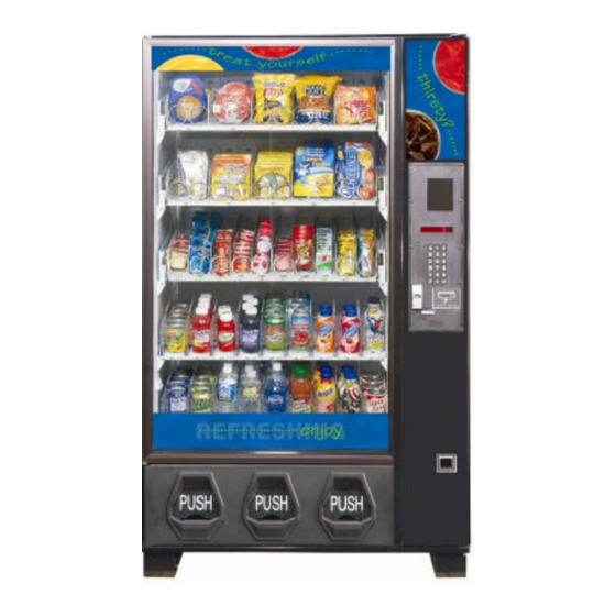
- Page 34 47.) Converted DN55## with Entray Snack Trays shown below. Figure 70 NOTE: VERIFY PROPER OPERATION OF THE VENDING MACHINE BY LOADING WITH PRODUCTS AND VENDING EACH COLUMN. Page 34 of 34...