Table of Contents
Advertisement
Quick Links
Advertisement
Table of Contents

Summary of Contents for Zenith ZeDrive
- Page 1 (217) 352-9330 | Click HERE Find the Colfax / Zenith Pumps ZeDrive at our website:...
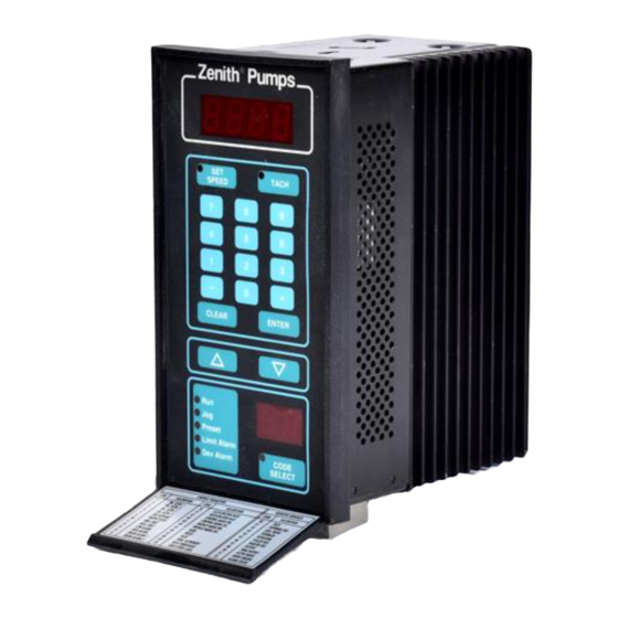
- Page 2 ZENITH PUMPS Date: 03/2006 ZeDrive DC Motor Drive User Manual Setup System Easily ® Zenith Pumps ZeDrive TACH SPEED CLEAR ENTER Preset Limit Alarm Dev Alarm CONTROL PARAMETERS MONITOR VARIABLES CODE DESCRIPTION CODE DESCRIPTION CODE DESCRIPTION PRI. SETPT 1 ACCEL RATE TACH PRI.
-
Page 3: Table Of Contents
ZENITH PUMPS TO GET ASSISTANCE, CALL: 919-774-7667 Page 2 Table of Content Introduction....................4 ZeDrive Standard Specification ............... 5 Standalone ZeDrive Wiring Diagram............6 Installation ....................7 Wiring Instructions................... 8 Control Cabinet Wiring ................9 Fielding Wiring..................10 Connect Input Power ...................10 Connect DC Motor Cable..................11... - Page 4 TO GET ASSISTANCE, CALL: 919-774-7667 Page 3 Table of Content Trouble-shooting & Fault Information (cont’d) Replaced Feedback Sensor Fits the Existing ZeDrive Or Not .......41 Display Shows “---1”, “---2” or “---3”..............41 Restore Back to Factory Defaults ................41 Can Not Operate from Keypad................42 The Display Would Not Light Up ................42...
-
Page 5: Introduction
In the event the drive assembly has to be located in a hazardous location, an optional intrinsically safe barrier is available to install in ZeDrive DC Motor drive cabinet to limit sensor current to safe levels. Refer to “ZeDrive Standard Specification” on next page for additional features and specifications. -
Page 6: Zedrive Standard Specification
ZENITH PUMPS TO GET ASSISTANCE, CALL: 919-774-7667 Page 5 ZeDrive Standard Specification Voltage Class Unit 115 VAC Class 230 VAC Class Rated Input Voltage 115 (104 ~ 132), 1 Phase 230 (207 ~ 264), 1 Phase 60/50 Rated Input Frequency... -
Page 7: Standalone Zedrive Wiring Diagram
TO GET ASSISTANCE, CALL: 919-774-7667 ZENITH PUMPS Page 6 Standalone ZeDrive Wiring Diagram Set By Switch! 115/230VAC DC Motor Neutral L2 Chassis Gnd Feedback White Sensor Black External Zero Speed High Alarm Power Low Alarm R-STOP Supply Dev Alarm 1 Dev Alarm 2 50V Max. -
Page 8: Installation
(top and bottom) Preset Limit Alarm Dev Alarm 5.7” • Insert ZeDrive from the panel front and slide it in 3.9” until it is flush with the panel surface. Ensure that supplied gasket is between the drive bezel and panel surface. •... -
Page 9: Wiring Instructions
ZeDrive that are considered non-routine, customers may have to wire to ZeDrive, too. If ZeDrive is ordered as a NEMA 4 standalone drive, customers are required to make all connections to the drive. -
Page 10: Control Cabinet Wiring
ZENITH PUMPS TO GET ASSISTANCE, CALL: 919-774-7667 Page 9 Control Cabinet Wiring... -
Page 11: Fielding Wiring
ZENITH PUMPS TO GET ASSISTANCE, CALL: 919-774-7667 Page 10 Field Wiring 1. Connect Input Power Customer supplies input AC power NOTE: Make sure to set power selection L2/Neutral switch to correct power voltage configura- Ground tion − 115/230 VAC, -10%, +15% −... -
Page 12: Connect Dc Motor Cable
ZENITH PUMPS TO GET ASSISTANCE, CALL: 919-774-7667 Page 11 Field Wiring (cont’d) 2. Connect DC Motor Cable • Permanent Magnet DC Motors Permanent magnet motor has only two motor connections for its arma- ture. The connections may be la- Motor... - Page 13 ZENITH PUMPS TO GET ASSISTANCE, CALL: 919-774-7667 Page 12 Field Wiring (cont’d) 2. Connect DC Motor Cable (cont’d) • Field Wound DC Motors Field wound motor has connections for its armature and field. Its armature connections will be labeled A1 and A2.
-
Page 14: Connect Feedback Signal Cable
ZENITH PUMPS TO GET ASSISTANCE, CALL: 919-774-7667 Page 13 Field Wiring (cont’d) 3. Connect Feedback Signal Cable Magnetic pickup or hall effect sensor is usu- +12VDC Feedback Signal ally located between motor and reducer. Common Encoder is usually located at the rear of mo- Ground tor. -
Page 15: Keypad & Display
ZENITH PUMPS TO GET ASSISTANCE, CALL: 919-774-7667 Page 14 Keypad & Display ® Zenith Pumps LED Display Control Keys TACH SPEED Numeric Keys CLEAR ENTER Code Select Key & Display Preset Limit Alarm Status LEDs CODE Dev Alarm SELECT •... -
Page 16: Keypad Operations
ZENITH PUMPS TO GET ASSISTANCE, CALL: 919-774-7667 Page 15 Keypad Operations Set New Speed Value ENTER Previous Display SPEED Current Set Speed New Set Speed Enter New Set Speed Tach Display TACH Actual Speed Previous Display Select Code & View Its Value... -
Page 17: Standard Programming
TO GET ASSISTANCE, CALL: 919-774-7667 Page 16 Standard Programming The codes below should meet the needs of most users for normal pump operations. If other NOTE: functions are desired from ZeDrive, consult “Complete Code List”. Code Description Value/Calculation Meaning Primary Setpoint 1... -
Page 18: Typical Applications & Solutions
ZENITH PUMPS TO GET ASSISTANCE, CALL: 919-774-7667 Page 17 Typical Applications & Solutions... -
Page 19: Quick Test For Zedrive
- J3 Pin 7 To AC 3. Connect Power to the Drive: Power • Turn the 120 VAC power on for the ZeDrive • If the power is 230 VAC, please refer to “Trouble- shooting” section 4. Configure ZeDrive: A 5.091:1 reducer and 120 teeth pickup gear is used for the following example. - Page 20 ZENITH PUMPS TO GET ASSISTANCE, CALL: 919-774-7667 Page 19 Quick Test for ZeDrive (cont’d) 5. Verify Feedback Signal Manually: ® Zenith Pumps • Click TACH • Turn the reducer shaft by a wrench • Non-zero number should be shown on the top display, when-...
-
Page 21: Connect Run/Stop Buttons
Use a momentary button • Connect the button to J3 connector Pin 12 and Pin 13 • When closed, ZeDrive will ramp up based on Accel- eration Time defined in Code 16 2. Stop Button: • Use a momentary button •... -
Page 22: Set And Display As Pump Rpm
ZENITH PUMPS TO GET ASSISTANCE, CALL: 919-774-7667 Page 21 Set and Display as Pump RPM 1. Preliminary Action: • Reducer Gear Ratio — R. If the pump is directly coupled with the motor, the gear ratio R=1 • Motor maximum speed — V (RPM) 2. -
Page 23: Set And Display As "Cc/Min
ZENITH PUMPS TO GET ASSISTANCE, CALL: 919-774-7667 Page 22 Set and Display as “cc/min” 1. Preliminary Action: • Reducer Gear Ratio — R. If the pump is directly coupled with the motor, the gear ratio R=1 • Motor maximum speed — V (RPM) •... -
Page 24: Set And Display As Other Units
ZENITH PUMPS TO GET ASSISTANCE, CALL: 919-774-7667 Page 23 Set and Display as Other Units 1. Preliminary Action: • Reducer Gear Ratio — R. If the pump is directly coupled with the motor, the gear ratio R=1 • Motor maximum speed — V (RPM) •... -
Page 25: Monitor Operation Status
1. Loosen up 6 screws on the back panel, and 2 screws located on the heat sink of ZeDrive 2. Remove the back panel, place ZeDrive as shown Heat Sink at left. The top board is the “Control Board”, and the bottom one is “Drive Board”... -
Page 26: Use 4-20 (Ma) As Setpoint
Motor maximum speed — V (RPM), 1800 (RPM) for most of systems supplied by Zenith • No. of Teeth of Feedback Gear — N, 120 for most of systems supplied by Zenith 2. Calculation: • To set the motor speed to be V (RPM) ( 0 ≤ V ≤ V ), the pump to be V (RPM) ( 0/R ≤... -
Page 27: Use 0-10 (Vdc) As Setpoint
Motor maximum speed — V (RPM), 1800 (RPM) for most of systems supplied by Zenith • No. of Teeth of Feedback Gear — N, 120 for most of systems supplied by Zenith 2. Calculation: • To set the motor speed to be V (RPM) ( 0 ≤ V ≤ V ), the pump to be V (RPM) ( 0/R ≤... -
Page 28: Feedback Control By Using A Flowmeter With Frequency Signal
1. Loosen up 6 screws on the back panel, and 2 screws located on the heat sink of Ze- Drive 2. Remove the back panel. Face the back of ZeDrive and place ZeDrive so that the heat sink points down. The top board is the “Control Board”, and the bottom one is “Drive Board”... - Page 29 ZENITH PUMPS TO GET ASSISTANCE, CALL: 919-774-7667 Page 28 Feedback Control by Using a Flowmeter with Frequency Signal (cont’d) 5. Result: • The output from the pump will be controlled by the flowmeter • The units of the setpoint and the Tach are same as the unit of F 6.
-
Page 30: Feedback Control By Using A Flowmeter With 4-20 (Ma) Signal
ZeDrive 2. Remove the back panel. Face the back of Ze- Drive and place ZeDrive so that the heat sink points down. The top board is the “Control Board”, and the bottom one is “Drive Board”... -
Page 31: Feedback Control By Using A Flowmeter With 0-10 (Vdc) Signal
ZeDrive 2. Remove the back panel. Face the back of Ze- Drive and place ZeDrive so that the heat sink points down. The top board is the “Control Board”, and the bottom one is “Drive Board”... -
Page 32: Master/Follower System
TO GET ASSISTANCE, CALL: 919-774-7667 Page 31 Master/Follower System 1. Preliminary Action: Feedback Jumper Location • Two individual ZeDrive systems are needed for forming Analog I/O Board (Not this jumper) a master/follower system • The following is only one example. For more detailed... - Page 33 NOTE: Do not count bare wire (shield wire) • Connect wires like the following illustration to form a master/follower system (for detailed connection, please refer to page G-4 in “ZeDrive and ZeTrol Manual” Master ZeDrive Follower ZeDrive Red (for 3-wire)
- Page 34 Stop the master system, the follower will also stop 6. IMPORTANT NOTE: • The above master/follower system is only a simplest example. For more detailed sys- tem integration and configuration, please refer to Chapter 5 in “ZeDrive and ZeTrol Manual”...
-
Page 35: Adjust Current Output Limit
Adjust Current Output Limit NOTE: The current limit level on ZeDrive is adjustable from approximately 4 to 16 amps. The current limit is not operable when ZeDrive is in Direct Scaling Mode (Code 61 = 0). 1. Preliminary Action: •... -
Page 36: Calibrate Analog Input
Calibrate Analog Input NOTE: In most instances, ZeDrive™ 2000 will come to you prepackaged in a control cabinet. The con- troller will be mounted and all internal cabinet wiring will be complete. The unit will also be programmed according to your specifications. The analog inputs and output will have been calibrated for 4-20mA, unless otherwise specified. -
Page 37: Calibrate Analog Output
Calibrate Analog Output NOTE: In most instances, ZeDrive™ 2000 will come to you prepackaged in a control cabinet. The con- troller will be mounted and all internal cabinet wiring will be complete. The unit will also be programmed according to your specifications. The analog inputs and output will have been calibrated for 4-20mA, unless otherwise specified. -
Page 38: Trouble-Shooting & Fault Information
ZENITH PUMPS TO GET ASSISTANCE, CALL: 919-774-7667 Page 37 Trouble-shooting & Fault Information... -
Page 39: Good Sensor Or Bad Sensor
• If the voltage always stay at 0 (VDC), or any value below 1 (VDC), please check the sensor wiring. If the wiring is correct, it may be a defected sensor. Please contact Zenith for a re- placed one •... -
Page 40: System Always Runs At Full Speed
2-wire Sensor: 3. There are 2 boards inside of ZeDrive. When Left you place ZeDrive as shown in step 2, the top board is the “Control Board”, and the bottom one is “Drive Board” 4. Locate Feedback Jumper as shown at left 5. -
Page 41: System Needs Help To Start To Rotate
9. System Needs Help to Start to Rotate: • Connect only A1 and A2 terminals on DC motor to ZeDrive A1 and A2 terminals, respec- tively. Leave F1 and F2 terminals unconnected •... -
Page 42: Replaced Feedback Sensor Fits The Existing Zedrive Or Not
16. Display Shows “- - - 1”, “- - - 2”or “- - - 3”: • If the AC power setting of ZeDrive sets to 230 VAC ( refer to 12 of this section), it may indi- cate that the actual AC power is 120 VAC •... -
Page 43: Can Not Operate From Keypad
20. How Do I Use ZeDrive for 230 (VAC) Power: • Locate the “Drive Board” inside of ZeDrive. Please refer to section “No Feedback Signal” • There is a “Power Selection Switch” on the “Drive Board”. Flip the switch so that it shows... -
Page 44: Fault Code List
ZENITH PUMPS TO GET ASSISTANCE, CALL: 919-774-7667 Page 43 Fault Code List Code Fault Description Corrective Actions This parameter establishes the minimum level of motor RPM during operation. It is allowable to program a set- LIMIT alarm LED lights up... -
Page 45: Complete Code List
ZENITH PUMPS TO GET ASSISTANCE, CALL: 919-774-7667 Page 44 Complete Code List... - Page 46 ZENITH PUMPS TO GET ASSISTANCE, CALL: 919-774-7667 Page 45 Default: Primary Setpoint 1 Default: Primary Setpoint 2 Default: Secondary Setpoint 1 Default: Secondary Setpoint 2 Units: eng Range: 0.000~9999 These codes have differing meanings, depending on the output format selected. They are always in Engineering Units.
- Page 47 ZENITH PUMPS TO GET ASSISTANCE, CALL: 919-774-7667 Page 46 Default: Maximum Limit 1800 Units: Motor RPM Range: 0~9999 This parameter establishes the maximum level of motor RPM during operation. It is allowable to program a setpoint which is above this value, however the...
- Page 48 TO GET ASSISTANCE, CALL: 919-774-7667 ZENITH PUMPS Page 47 Default: Acceleration Time 600.0 Default: Deceleration Time 600.0 Units: Seconds Range: 0.0~600.0 These parameters control the rate at which the desired speed is ramped up/down. It is the number of seconds required to change the motor speed by 1800 RPM.
- Page 49 ZENITH PUMPS TO GET ASSISTANCE, CALL: 919-774-7667 Page 48 Default: Primary Display Maximum 1800 Units: eng Range: 0~9999 This parameter is similar to C20, but will be used for display, thus allowing a scale factor to be introduced between the controlled process and the display. The...
- Page 50 ZENITH PUMPS TO GET ASSISTANCE, CALL: 919-774-7667 Page 49 Default: Max RPM External Reference - Primary 1800 Units: PPR (Number of Pulses Per Revolution) Range: 0~3270 It sets the full-scale speed of the device driving External Reference, and is used in Follower or Offset formats when the primary data set is selected.
- Page 51 Read Only Units: eng Range: It is the feedback displayed in scaled Engineering Units. The feedback input is read by ZeDrive every 10 milliseconds. The readings are summed and averaged for one second before displaying External Reference Input Read Only...
- Page 52 ZENITH PUMPS TO GET ASSISTANCE, CALL: 919-774-7667 Page 51 Feedback Frequency Input Read Only Units: Hz Range: It displays the frequency of Feedback Frequency Input in hertz (pulses per second). The number displayed is not averaged. It represents the frequency calculation from the prior 10 milliseconds before the display update.
- Page 53 ZENITH PUMPS TO GET ASSISTANCE, CALL: 919-774-7667 Page 52 Entry Error Read Only Units: Range: No Error Invalid Code Above Maximum Value Below Minimum Value Keypad Lockout Entry Timeout It shows the last error encountered on a keypad entry. If any entry is not accepted by the controller, the reason shows up here.
- Page 54 ZENITH PUMPS TO GET ASSISTANCE, CALL: 919-774-7667 Page 53 Analog Input 1 Raw Signal Read Only Units: mA / VDC Range: It is Analog Input 1 signal unadjusted for Zero and Span. Analog Input 1 Adjusted Signal Read Only Units: bits Range: It is Analog Input 1 signal adjusted for Zero and Span.
- Page 55 ZENITH PUMPS TO GET ASSISTANCE, CALL: 919-774-7667 Page 54 Default: Secondary Display Format Units: Range: Master Follower These parameters are used to select Display Format used when primary and secondary data sets are selected, respectively. Default: Gain 5000 Units: Range: 0~9999 This parameter sets Gain in PID control loop.
- Page 56 TO GET ASSISTANCE, CALL: 919-774-7667 ZENITH PUMPS Page 55 Default: Rate Threshold Units: Hz Range: 0~100 This parameter sets a threshold, below which the Rate term (derivative term) has no affect on PID control loop. In many cases, Rate is not needed, or is needed only...
- Page 57 ZENITH PUMPS TO GET ASSISTANCE, CALL: 919-774-7667 Page 56 Default: Zero Speed Logic Units: Range: 0~1 It dictates the operation of Zero-speed alarm output. If set to 0, the output is controlled only by the ramped reference (M-46); if set to 1, the output is controlled by both the ramped reference (M-46) and the feedback (M- 43).
- Page 58 ZENITH PUMPS TO GET ASSISTANCE, CALL: 919-774-7667 Page 57 Default: Analog Output Range 4095 Units: Range: It establishes the value at which the analog output is 10VDC or 20 mA. Default: Analog Output ZERO 1024 Units: Range: 0~2048 It allows user to zero-adjust the analog output, as part of the calibration process.
-
Page 59: System Drawings
ZENITH PUMPS TO GET ASSISTANCE, CALL: 919-774-7667 Page 58 System Drawings... - Page 60 ZENITH PUMPS TO GET ASSISTANCE, CALL: 919-774-7667 Page 59...
- Page 61 ZENITH PUMPS TO GET ASSISTANCE, CALL: 919-774-7667 Page 60...
- Page 62 ZENITH PUMPS TO GET ASSISTANCE, CALL: 919-774-7667 Page 61...
- Page 63 Zenith Pumps ZENITH PUMPS Zenith Pumps 5910 Elwin Buchanan Drive Sanford, NC 27330 Phone: 800-277-8968 Fax: 919-774-5952 E-mail: zenithpumps@zenithpumps.com...