Table of Contents
Advertisement
INSTRUCTION MANUAL
HITACHI
HIGH-SPEED REFRIGERATED CENTRIFUGES
Thank you for purchasing the Hitachi
high-speed refrigerated centrifuge.
Before using this centrifuge,
carefully read through
this instruction manual to ensure
efficient and safe operation.
Keep this instruction manual handy.
・
The appearance or specification of the products covered in this manual is
subject to partial change for improvement.
CR22N/CR21N
2015.10
S99840305
Advertisement
Table of Contents

Related Manuals for Hitachi CR22N


Summary of Contents for Hitachi CR22N
- Page 1 INSTRUCTION MANUAL HITACHI HIGH-SPEED REFRIGERATED CENTRIFUGES CR22N/CR21N Thank you for purchasing the Hitachi high-speed refrigerated centrifuge. Before using this centrifuge, carefully read through this instruction manual to ensure efficient and safe operation. Keep this instruction manual handy. ・ The appearance or specification of the products covered in this manual is subject to partial change for improvement.
- Page 3 Copyright © 2015 Hitachi Koki Co., Ltd. All rights reserved. No part of this document may be reproduced or transmitted in any form or any means without permission from Hitachi Koki Co., Ltd. The names of actual companies and products mentioned herein may be the trademarks of their respective owners.
- Page 4 "NOTE" indicates a note which has no direct bearing on personal safety. Do not perform any operation not specified in the instruction manual. If any problem is found on your instrument, contact a Hitachi Koki authorized sales/service representative. Although the safety precautions in the instruction manual and safety instructions on your instrument have been fully considered, an unexpected situation may arise.
- Page 5 If abnormal sound or vibration occurs, stop the operation immediately and contact a ● Hitachi Koki authorized sales/service representative. CAUTION: Before using a rotor, be sure to read through the rotor instruction manual. ●...
- Page 6 CR21N refrigerated centrifuge. A continuous flow rotor is not applicable to the CR21N refrigerated centrifuge. Installation or relocation of your centrifuge must be done by the authorized Hitachi ● Koki service representative. Contact a Hitachi Koki authorized sales/service representative.
- Page 7 Hitachi Koki authorized sales/service representative. Notice for an Earthquake Depending on the magnitude, an earthquake might damage the centrifuge. If you observe some abnormality, stop using the centrifuge immediately and ask for inspection by the Hitachi Koki service representative.
-
Page 8: Table Of Contents
2-2-1 Setting Run Conditions 2-2-2 Operational Procedure ······································································· 2-9 ··············································· 2-12 2-2-3 Acceleration Rate and Deceleration Rate 2-2-4 Variable Deceleration Slope Function (CR22N only) ·································· 2-13 2-3 How to Use the FUNCTION Area ······························································· 2-15 2-3-1 Programmed Operation ····································································· 2-16 ········································································... - Page 9 Table of Contents 4. Troubleshooting ·········································································································· 4-1 4-1 Alarm Messages ····································································································· 4-2 (1) Corrective actions ····························································································· 4-2 4-2 User-Corrected Problems ······················································································· 4-3 5. Installation and Relocation ······················································································· 5-1 6. Warranty ······················································································································· 6-1 6-1 Warranty on Centrifuge ··························································································· 6-1 6-2 Warranty on Rotor ·································································································· 6-1 7 .
- Page 10 MEMO...
-
Page 11: External View Of Centrifuge
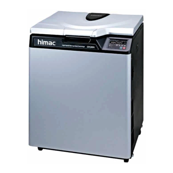
1. Structure 1-1 External View of Centrifuge 1. Structure This section explains the appearance and the structure of the main components of the CR-N series refrigerated centrifuge. 1-1 External View of Centrifuge 760 mm (29.9 in) 700 mm (27.6 in) 853 mm (33.6 in) Ultrasonic sensor Door... -
Page 12: Structure
1-2 Structure 1-2-1 Touchscreen 1-2 Structure 1-2-1 Touchscreen The touchscreen with color liquid crystal screen is incorporated in this centrifuge. You can set the run conditions, perform the operation, and display Run History, Programmed Run, and User Customizations Screens by pressing the screen. Fig. - Page 13 Displays deceleration modes 1 through 9, along with free coasting (0). Displays “SLOW” or “FREE”, and deceleration mode change speed when the DECEL SLOPE (variable deceleration slope function) is chosen. (CR22N only) button Press this button to start rotor rotation.
- Page 14 Functions and actions Name and symbol USB (host side) (10) Use the USB connection to output the operation history of the centrifuge to USB (10) memory. (CR22N only) USB (device side) (11) Use for connecting optional items. (11) (12) Use for connecting the LAN cable (to establish communication between “himac (12) LogManager”...
-
Page 15: Power Switch
1-2-2 POWER Switch 1-2-3 Safety Device 1-2-2 POWER Switch The POWER switch applies electric power to the centrifuge. 「|」:ON 「○」:OFF POWER switch Fig. 1-2-2 POWER Switch 1-2-3 Safety Device (1) Protector of rotor chamber The rotor chamber allows the rotor to rotate at high speed. To prevent any rotor mishap during centrifugation, a steel protector is provided around the chamber for operator safety. -
Page 16: Operation
This function is used to limit the users of the Section 2-6-4 (2) Lockout system function centrifuge. "User Lockout" This function is used to separate samples that disturbed during Section 2-2-4 deceleration. Variable " Variable deceleration Deceleration slope function Slope Function (CR22N only)" Time... -
Page 17: Run Preparation
2-1 Run Preparation 2-1-1 Starting up This Machine 2-1 Run Preparation WARNING:1. This centrifuge is not explosion proof centrifuge. Never use explosive or flammable samples, or materials that chemically react vigorously. Do not centrifuge such materials in this instrument nor handle or store them near the instrument. 2. -
Page 18: Rotor
CR21N refrigerated centrifuge. A continuous flow rotor is not applicable to the CR21N refrigerated centrifuge. CAUTION : 1.Read the rotor instruction manual thoroughly before use. 2.Never use any adapter, tube or bottle that is not designated for the centrifuge by Hitachi Koki. 3.Mount the rotor cover securely. -
Page 19: Basic Operation
CAUTION: 1. Do not press the touchscreen with a sharp-pointed object such as a ballpoint pen. 2. If abnormal sound is heard during the operation, stop the operation immediately and contact a Hitachi Koki authorized sales/service representative. 2-2-1 Setting Run Conditions This section will first describe the screen for basic operation (the Run screen). - Page 20 2-2-1 Setting Run Conditions [Display and operations when entering the run parameters] The on-screen keypad appears by pressing the SPEED area, TIME area, TEMP, or ACCEL/DECEL area. (1) Press the area of the desired item to turn the upper part blue. Color of the upper part:Blue (2) Enter the desired numeric value with the on-screen keypad.
- Page 21 2-2-1 Setting Run Conditions The next page describes how to set run condition by citing some examples. NOTE (1) If you enter the wrong value, press the CE button and then enter the correct value. If you have pressed the Enter button, repeat step (1) of the previous page, and then enter the correct value.
- Page 22 2-2-1 Setting Run Conditions • How to set speed, running time, and temperature Here are some examples and descriptions: Running time Temperature Setting item (SPEED) (TIME) (TEMP) Typical setting 22,000rpm 2 minutes 30 seconds 4 °C Press the SPEED,TIME, or TEMP area to show the on-screen keypad.
- Page 23 • How to set acceleration, deceleration, and deceleration slope Here are some examples and descriptions: Deceleration slope Deceleration Acceleration Setting item (DECEL SLOPE) (DECEL) (ACCEL) (CR22N only) Typical setting FREE-10000rpm Press the ACCEL/DECEL area to show the on-screen keypad. Press the area of the desired item. Color:Blue...
-
Page 24: Operational Procedure
2-2-2 Operational Procedure 2-2-2 Operational Procedure Given below is a description of the operational procedure for a normal run. NOTE Before starting up this machine, carefully read the operation manual for your rotor and make sure that you have selected the correct type of tubes and injected the correct amount of sample. - Page 25 2-2-2 Operational Procedure Step Touch panel operation Screen displays and notes STOP button blinks rotor starts The specified centrifugation time elapses (time-out) or decelerating. press the STOP button. NOTE When the rotor starts decelerating, you can hear the hissing sound from the centrifuge for about three seconds.
- Page 26 2-2-2 Operational Procedure Fig. 2-2-2 summarizes the operational procedure. START Turn on the POWER switch. Open the door and install rotor.。 For information on how Close the door and set to set the run conditions, the run conditions.。 see section 2-2-1. Reaches the set time or press the STOP button.。...
-
Page 27: Acceleration Rate And Deceleration Rate
2-2-3 Acceleration Rate and Deceleration Rate 2-2-3 Acceleration Rate and Deceleration Rate The acceleration and deceleration rates can be adjusted for a wide range of use. The figure below shows how a rotor accelerates and decelerates in compliance with a code number selected from among 1 through 9. -
Page 28: Variable Deceleration Slope Function (Cr22N Only)
2-2-4 Variable Deceleration Slope Function 2-2-4 Variable Deceleration Slope Function (CR22N only) The variable deceleration slope function is designed for this centrifuge. Two slower deceleration slopes are selectable in addition to the same slope as the well-reputed slope of the conventional centrifuges. - Page 29 2-2-4 Variable Deceleration Slope Function 【Screen for setting the DECEL SLOPE (Example: “SLOW-7000rpm”)】 Fig. 2-2-4 (2) shows the screen for setting the DECEL SLOPE. “SLOW-7000rpm” is displayed in the Run screen (see fig. 2-2-4 (3)). Fig. 2-2-4 (3) Fig. 2-2-4 (2) *Refer to section 2-2-1 for setting the DECEL SLOPE.
-
Page 30: How To Use The Function Area
2-3 How to Use the FUNCTION Area 2-3 How to Use the FUNCTION Area This centrifuge incorporates a number of features, such as step-mode and other programmed running, display and setting of centrifugal force, and RTC (real-time control) that can run the centrifuge at a required date and time. -
Page 31: Programmed Operation
2-3-1 Programmed Operation 2-3-1 Programmed Operation When a centrifugal condition is to be used frequently, entering the same condition every time you want to perform centrifugation is inconvenient. This centrifuge has a programmed operation feature that stores run conditions. Storing run conditions which you often use allows you to call those conditions however often you may wish, thus saving time in setting. - Page 32 2-3-1 Programmed Operation (Basic operation of the programmed operation feature) Press the PROGRAM button. Box (for displaying a program No.) Program No. of the loaded run parameters is displayed. Press the box (for displaying a program No.) (color: gray). If the run parameters are stored, SPEED,TIME,TEMP, and REMARK are displayed.
- Page 33 2-3-1 Programmed Operation The pressed row turns blue. Press the button. If you perform the programmed operation, Press the Select button. If you create or change a program, If you delete a program, Press the Delete button. Press the button to go back to the Run screen. The loaded run parameters are displayed in the Run screen.
- Page 34 2-3-1 Programmed Operation (1) Programming procedure for run conditions (creating or changing) Shown below is the procedure for storing (creating) or changing an run condition. Step Touch panel operation Screen displays and notes In the FUNCTION area of the Run screen, press the button.
- Page 35 2-3-1 Programmed Operation Step Touch panel operation Screen displays and notes Press t he box (for displaying a The PROGRAM program No.). screen appears. If a SPEED, REMARK, etc. are displayed in the row of a ○ program No., run parameters have already been stored for that program.
- Page 36 ACCEL:9 / DECEL:9 ROTOR:R22A4 RCF:6420 SAMPLE HEIGHT:0 g.sec:----- REMARK:hitachi koki b) After entering the run (If you do not enter the numeric value for ACCEL, the following screen appears.) parameters, press OK button. Entering numeric values...
- Page 37 2-3-1 Programmed Operation Step Touch panel operation Screen displays and notes Press PROGRAM program No. for which you screen appears. created changed) program, and make sure that the pressed row turns blue. Then press the RUN button. (If you pressed the row of the program No.4, turned...
- Page 38 2-3-1 Programmed Operation (2) How to perform a programmed operation Shown below is how to perform a “programmed operation”, that is, how to call a stored set of run parameters and run this centrifuge accordingly. (a) If you know the program No. you need Step Touch panel operation Screen displays and notes...
- Page 39 2-3-1 Programmed Operation Step Touch panel operation Screen displays and notes Press the row of the program No. for which you want to run a program, and make sure that the pressed row turns blue. Then press the RUN button. RUN button The loaded run ●...
- Page 40 2-3-1 Programmed Operation (b) If you do not know the Program No. of the program which you need Step Touch panel operation Screen displays and notes ○ Runscreen appears. Turn on the POWER switch on the centrifuge. In the FUNCTION area of the Run screen, press the button.
- Page 41 2-3-1 Programmed Operation Step Touch panel operation Screen displays and notes Press the row of the program No. for which you want to check a program, and make sure that the pressed row turns blue. Then press the Select button. Select button RUN button...
- Page 42 2-3-1 Programmed Operation NOTE (1) To perform a combination of a programmed run with RTC (see Section 2-3-5 “RTC (real-time control) Operation”), call a programmed memory unit, then set RTC. The system will then calculate the total of the running times of all steps of the programmed run and calculate the start time for RTC.
- Page 43 2-3-1 Programmed Operation (3) Deleting a program This section explains how to delete a program. NOTE You cannot delete a program while in running (while the rotor is rotating). Always perform this function while not in running. Step Touch panel operation Screen displays and notes In the FUNCTION area of the Run screen, press the...
- Page 44 2-3-1 Programmed Operation Step Touch panel operation Screen displays and notes The deletion Press the row of the program ● confirmation box No. for which you want to is displayed. delete a program, and make sure that the pressed row turns blue.
-
Page 45: Step-Mode Operation
2-3-2 Step-Mode Operation 2-3-2 Step-Mode Operation This centrifuge has the step-mode operation capability that allows you to save three different sets of values for a run parameter set in a single memory location (program No. 31 - 33, 41 - 43, and 51 - 53) and then change some or all of the run conditions (e.g., speed, run time, rotor temperature, etc.) for each step during a step-mode run. - Page 46 2-3-2 Step-Mode Operation NOTE (1) Select the same rotor for each step. Otherwise, the centrifuge can not perform the step-mode operation. (2) Use the program No. 32 and 33 (42 and 43 or 52 and 53) for the step-mode operation with two steps.
-
Page 47: Displaying And Setting Rcf
2-3-3 Displaying and Setting RCF 2-3-3 Displaying and Setting RCF This centrifuge stores the maximum and average radii of each rotor in the internal memory. Setting a speed causes this centrifuge to automatically calculate and display the RCF (relative centrifugal force) value, while setting an RCF value causes the centrifuge to automatically calculate and display the speed. - Page 48 2-3-3 Displaying and Setting RCF Step Touch panel operation Screen displays and notes Rotor which you selected Press the box (for displaying a RCF(g)). Screen for ● setting a RCF value appears. Specified setting of a SAMPLE HEIGHT Specified setting of a SPEED Specified setting of a RCF value...
- Page 49 2-3-3 Displaying and Setting RCF Step Touch panel operation Screen displays and notes [Setting a RCF value and SPEED] a) Enter the desired numeric value with the on-screen e.g.) RCF(g) value: “47500” keypad. Entered numbers are moved to the left every time a new number is entered.
- Page 50 2-3-3 Displaying and Setting RCF Step Touch panel operation Screen displays and notes [Setting a Sample Height] [Setting a Sample Height] e.g.) Sample Height: “10” Press the SAMPLE HEIGHT area. a) The area (for choosing between the RCF calculation a) Press the SPEED RCF calculation button or calculation) appears.
- Page 51 2-3-3 Displaying and Setting RCF Step Touch panel operation Screen displays and notes If you do not need to set a The Run screen RCF value or a SPEED, press ● appears. the x button. The Run screen reappears. New specified setting New specified setting of a Sample Height of a RCF value...
-
Page 52: Displaying And Setting G . Sec
2-3-4 Displaying and Setting g . sec 2-3-4 Displaying and Setting g . sec This section describes how to display and set a g . sec. (1) How to display and set a g . sec value Step Touch panel operation Screen displays and notes Check that the desired rotor is displayed in the ROTOR... - Page 53 2-3-4 Displaying and Setting g . sec Step Touch panel operation Screen displays and notes Press the area of desired The specified ● item. setting turns blue. Color: blue If you want to change other settings, press the area of the ○...
- Page 54 2-3-4 Displaying and Setting g . sec Step Touch panel operation Screen displays and notes The Run screen ● Press the x button, appears. and then the Run screen reappears. “--:--” is displayed in the lower part of the TIME area by ○...
-
Page 55: Rtc (Real-Time Control) Operation
2-3-5 RTC (real-time control) Operation 2-3-5 RTC (real-time control) Operation This centrifuge contains an internal clock, allowing you to run the machine at a specified start or finish time for centrifugation. This feature for running the machine at a specified time is called the RTC (real-time control) feature. - Page 56 2-3-5 RTC (real-time control) Operation (1) How to perform an RTC operation Step Touch panel operation Screen displays and notes In the Run screen, enter the run parameters. In the FUNCTION area of the RTC button Run screen, press the button.
- Page 57 2-3-5 RTC (real-time control) Operation Step Touch panel operation Screen displays and notes Press the Enter button. The START confirmation box appears. Press the START button. The RTC operation does not get activated unless you press the START button. If you want to cancel the The START time and STOP time for centrifugation are ○...
- Page 58 2-3-5 RTC (real-time control) Operation NOTE 1. You cannot make an RTC setting in any of the following cases: (1) When the Run screen is set to HOLD (continuous run) Set the run time (centrifugation time) not to HOLD but to a numerical value. (2) When it is past the start time Set the start time to a time later than the current time.
-
Page 59: Selecting The Rotor
2-4 Selecting the Rotor 2-4 Selecting the Rotor This centrifuge stores the maximum and average radii of each rotor in the internal memory. Setting a speed causes this centrifuge to automatically calculate and display the RCF (relative centrifugal force) value, while setting an RCF value causes the centrifuge to automatically calculate and display the speed. - Page 60 2-4 Selecting the Rotor Step Touch panel operation Screen displays and notes The ROTOR When the desired rotor is not ● displayed, press the CATALOG screen appears. Rotor Catalog button. In the ROTOR CATALOG screen, press the field of the desired rotor type.
-
Page 61: User Login
2-5 User Login 2-5 User Login After logging in, individual users can control the operation history of the centrifuge. (1) Procedure for user login Step Touch panel operation Screen displays and notes In the Run screen, press the USER area. USER area In the User Management The User... - Page 62 2-5 User Login Step Touch panel operation Screen displays and notes The user name is displayed in Run screen the USER area of the Run reappears . screen. USER area NOTE (1) User login is required to start operation when the user lockout function has been enabled as described in Section 2-6-4 (2) “User Lockout.”...
-
Page 63: Features Of The Menu Screen
2-6 Features of the MENU Screen 2-6 Features of the MENU Screen The Menu screen appears by pressing the MENU screen tab on the Touchscreen. These features are designed to allow you to use this centrifuge with additional handy options (see figure 2-6). MENU tab Total operation hours of this centrifuge... -
Page 64: Displaying The Run History And Loading The Information About Run Parameters
2-6-1 Displaying the Run History and Loading the Information About Run Parameters 2-6-1 Displaying the Run History and Loading the Information About Run Parameters The information about 100 sets of the run parameters of the previous normal operations can be stored automatically in the centrifuge and you can load it for a new run. Step Touch panel operation Screen displays and notes... -
Page 65: Rotor Catalog
2-6-2 Rotor Catalog 2-6-2 Rotor Catalog You can view the applicable rotor names and their specifications. Step Touch panel operation Screen displays and notes The ROTOR Press the Rotor Catalog CATALOG icon in the MENU screen. screen appears. The screen for ... -
Page 66: Customizing The Settings
2-6-3 Customizing the Settings 2-6-3 Customizing the Settings You can customize the settings in the Run screen and the settings in the CUSTOM screen such as the stop signal, sound volume and backlight. In the MENU screen, press the Customize icon. - Page 67 2-6-3 Customizing the Settings (1) Zoom The display on the Run screen can be zoomed 1. Normal:Displays the ordinary Run screen 2.Zoom:The speed and time display is zoomed when 20 seconds have passed after reaching the set speed. Fig. 2-6-3 (1) Zoom Setting screen Press either the NORMAL or ZOOM button and make sure that the selected button is surrounded with a green frame.
- Page 68 2-6-3 Customizing the Settings (4) Backlight setting The brightness of the screen can be adjusted. Dimming backlight mode can be specified. Adjusting the brightness The backlight brightens up as the green range in the backlight setting indicator increases. The backlight level is darkest if there is only the black range.
- Page 69 2-6-3 Customizing the Settings (5) Pre-cool setting Pre-cool can be specified. The temperature in the rotor chamber is controlled at about 15 C by selecting “Pre-cool”. Presence of a rotor is automatically detected when closing the door and the temperature in the rotor chamber is controlled at about 15 C if no rotor is Fig.
-
Page 70: Administrator (Admin) Functions
2-6-4 Administrator (Admin) Functions 2-6-4 Administrator (Admin) Functions You can set the admistrative items such as language mainly. In the MENU screen, press the Manager(Admin) icon. Then the ADMIN screen showing the nine functions is displayed as shown in Fig. 2-6-4. Tab of each screen Fig. - Page 71 Centrifuge ID can be set for identification Service contact (see Section 2-6-4 (7)). The operation history data of the centrifuge can be exported to a USB flash drive. (CR22N only) USB/LAN(option) communication If your centrifuge has a LAN communication option, LAN communication start/stoppage can be specified.
- Page 72 2-6-4 Administrator (Admin) Functions (1) User Management You can register up to 40 users with the system. How to store (register) and how to change a user name are described below. Step Touch panel operation Screen displays and notes The User ●...
- Page 73 2-6-4 Administrator (Admin) Functions Step Touch panel operation Screen displays and notes Register the user name and press the Enter button. Enter button PIN box The PIN registration screen is displayed. The masked PIN Enter the desired PIN number number is (4 digits) in the PIN box and displayed.
- Page 74 User on the same access level Management with the administrator, press screen. Administrator in the access “Hitachi-Koki” is level selection box. If you do not want to place the added to the user registered user on the same name and access level with the “Administrator”...
- Page 75 2-6-4 Administrator (Admin) Functions (2)User Lockout Enable : User login is required to start operation. You can not set run conditions and start operation without logging in. Prior user registration is required. (See Section 2-6-4 (1) “User Management” and 2-5 “User login”.) In addition, login of a user having the administrator access Fig.
- Page 76 2-6-4 Administrator (Admin) Functions (4) Rotor Management You can use and control the rotor data such as total operation hours and number of runs by registering your rotors in the centrifuge in advance. 1) Registering the rotor Step Touch panel operation Screen displays and notes Register the rotor as follows: a)The Rotor...
- Page 77 2-6-4 Administrator (Admin) Functions Step Touch panel operation Screen displays and notes d) The Enter S/N e) Enter (Serial screen appears. number ) and press the Enter a 4-digit ● Enter button. number: In the case of “123,” prefix zero to the Registration is number (“0123”).
- Page 78 2-6-4 Administrator (Admin) functions Step Touch panel operation Screen displays and notes The total number ● Enter the total operation hours of runs of a rotor of the rotor as follows: having operation a) In the Rotor Management history can be screen, press the row of the registered.
- Page 79 2-6-4 Administrator (Admin) functions Step Touch panel operation Screen displays and notes The total number Enter the total number of runs ● of runs of a rotor of the rotor as follows: having operation a) In the Rotor Management history can be screen, make sure that the registered.
- Page 80 2-6-4 Administrator (Admin) functions 2) Deleting a registered rotor Step Touch panel operation Screen displays and notes In the ADMIN screen, press The Rotor ● Management the Rotor Management screen appears. icon. In the Rotor Management The deletion ● screen, press the row of the confirmation box rotor which you want to is displayed.
- Page 81 2-6-4 Administrator (Admin) Functions (5) Actual Run Timer setting <Actual Run Timer is enabled.> When you press the Enable button, the timer starts counting after reaching the set speed. <Actual Run Timer is not enabled.> When you press the Disable button, Fig.
- Page 82 Fig. 2-6-4 (7) Enter Service Contact screen (8) USB/LAN communication [USB MEMORY] (CR22N only) The operation history of the centrifuge can be output in CSV format* to a USB flash drive on the market. *CSV format: This is a versatile file format that is compatible with spreadsheet softwares.
- Page 83 (2) Be sure to back up your data before using the USB flash drive. Hitachi Koki will not be liable for any data loss.
- Page 84 Add button. Input the rotor registration The Input item data in the field No.1-No.20. screen appears. NOTE For the rotor registration data, contact a Hitachi Koki authorized sales/service representative. < : Previous Page button > : Next Page button 2-69...
- Page 85 2-6-4 Administrator (Admin) functions Step Touch panel operation Screen displays and notes Press the field which you want to input the rotor registration data in. Press the field. A screen to input the rotor registration data is displayed. e.g.) If you press the field No.1, the screen to input the rotor registration data of the field No.1 is displayed (see below).
- Page 86 2-6-4 Administrator (Admin) functions Step Touch panel operation Screen displays and notes Complete inputting the rotor registration data in all fields (No.1-No.20) and then press the Register button. (If the rotor registration data is not correct, you can not register the rotor.) Register button The rotor ●...
- Page 87 2-6-4 Administrator (Admin) functions Step Touch panel operation Screen displays and notes Press the OK button on the rotor registration completion box and then press x button in the Input item screen to return the Rotor data OK button addition screen. x button The added rotor is ●...
- Page 88 2-6-4 Administrator (Admin) functions 2) Deleting an added rotor Step Touch panel operation Screen displays and notes In the ADMIN screen, press The Rotor data addition Rotor data addition screen appears. icon and then press the row you want to delete the rotor. Press the row.
- Page 89 2-6-4 Administrator (Admin) functions Step Touch panel operation Screen displays and notes Press the Delete button. Delete button The deletion ● confirmation box is displayed. The added rotor ● Press the button on is deleted. the deletion conformation box. 2-74...
-
Page 90: Emergency Recovery From Power Failure
2. Never attempt to slow or stop the rotor by hand. CAUTION: Do not perform any operation not specified in this manual. If any problem is found on your centrifuge, contact a Hitachi Koki authorized sales/service representative. (1) Rotation of rotor The rotating rotor coasts free and finally stops if a power failure occurs during operation. - Page 91 2-7 Emergency Recovery from Power Failure 1. Check that the rotor stops completely. 2. If your centrifuge is equipped with a three wire cord, turn off the POWER switch of the centrifuge and turn off the distribution board of your centrifuge room. If your centrifuge is equipped with a power cord with a plug, turn off the POWER switch of the centrifuge and unplug the power cord from the receptacle.
-
Page 92: Maintenance
Hitachi Koki may ask you about the treatment for the centrifuge, rotor or the part if the decontamination is checked and judged as insufficient by Hitachi Koki. It is your responsibility to bear the cost of sterilization or decontamination. -
Page 93: Rotor Chamber
Refer to the chemical resistance chart provided with the rotor, or contact Hitachi Koki. CAUTION: For sterilization of the surface of the centrifuge and the rotor chamber, wipe them with a cloth dampened with 70% ethanol. -
Page 94: Rotor
3-4 Rotor 3-5 Replacement Parts 3-6 Others 3-4 Rotor (1) To prevent corrosion, take out the rotor from the rotor chamber after operation and remove the rotor cover to dry the tube holes. (2) If any sample is spilt inside the rotor, wash and dry the rotor well, then apply silicone grease (vacuum grease) lightly to the rotor. -
Page 95: Troubleshooting
Hitachi Koki may ask you about the treatment for the centrifuge, rotor or the part if the decontamination is checked and judged as insufficient by Hitachi Koki. It is your responsibility to bear the cost of sterilization or decontamination. -
Page 96: Alarm Messages
WARNING:Unspecified repairs, remodeling or disassembly of the centrifuge that is not listed below is strictly prohibited by any person other than a Hitachi Koki authorized services representative. After taking the actions, if the problem still persists, contact a Hitachi Koki authorized sales/service representative to ask for repair. -
Page 97: User-Corrected Problems
If any of the alarm messages E10 to E95 lights up, it is indicating that the centrifuge has a problem and requires maintenance by Hitachi Koki service representative. When you call the service personnel, tell them the displayed alarm code. -
Page 98: Installation And Relocation
5. Installation and Relocation 5. Installation and Relocation Installation or relocation of your centrifuge must be done by the authorized Hitachi Koki service representative. Contact your local dealer or a Hitachi Koki service representative. Observe the following instructions for installation or relocation of your centrifuge. - Page 99 5. Installation and Relocation (3) Power cord WARNING: Your centrifuge must be grounded properly to avoid electrical shock hazards. WARNING: Do not touch the power cord with wet hands to avoid electrical shocks. 1) When your centrifuge is equipped with a three wire power cord (see below), plug the power cord coming from the rear of the centrifuge in the terminal of the distribution board in accordance with ANSI/NFPA 70, NEC, with CSA C22.1, CEC, Part Ⅰ...
- Page 100 Keep the cap on. Be careful not to lose it. Drain hose Clamp (small) Clamp (big) Installation or relocation of your centrifuge must be done by the authorized Hitachi Koki service representative. Contact a Hitachi Koki authorized sales/service representative.
-
Page 101: Warranty
Buyer with transportation charges prepaid. Hitachi Koki will be released from all obligations under this warranty in the event that any such instruments have been installed by, or repairs or modifications are made by, persons other than its own or service personnel authorized by it unless such installation, modification and/or repairs by others are made with the prior written consent of Hitachi Koki. -
Page 102: Specifications
7. Specifications 7. Specifications CR22N CR21N Maximum speed 22,000 rpm 21,000 rpm 55,200xg 53,200xg Maximum RCF (R22A4 rotor) (R21A rotor) 6,000ml 4,000ml Maximum capacity (nominal) (R9A2 rotor) (R9A rotor) Set speed 300 to 22,000rpm 300 to 21,000rpm Set temperature -20º C to +40º C 1 second to 99 minutes and 59 seconds;... - Page 103 22N/CR21N centrifuges. Only the rotors with overspeed adapters (magnets) must be used. The CR22N refrigerated centrifuge does not conform to the CE marking requirements when using a continuous flow rotor due to the construction of the rotor. A continuous flow rotor is not applicable to the CR21N refrigerated centrifuge.
-
Page 104: List Of Standard Accessories
List* of applicable rotors S998492 Summarized sheet of S998317 instruction manual S998320 Instruction manual (Only for the CR22N centrifuges (Not conforming to CE that do not conform to CE Marking Marking requirements) requirements) S205386A Rear duct ass'y (To be mounted to the rear cover... -
Page 105: Tubes And Bottles
9. Tubes and Bottles 9.Tubes and Bottles Cleaning and sterilizing tubes and bottles Use the best method for cleaning and sterilizing tubes and bottles, referring to the table below. Cleaning and sterilizing conditions for tubes and bottles : Applicable : Inapplicable Material Condition... - Page 106 9. Tubes and Bottles Conditions and life expectancy of tubes and bottles CAUTION:Do not use tubes/bottles that have exceeded their life expectancy. Failure to do so could result in damage of tubes/bottles and the rotor and the centrifuge. The life expectancy of tubes/bottles depends on factors such as the characteristics of samples, speed of the rotor used, and temperature.
- Page 107 APPENDIX...
-
Page 108: Decontamination Sheet
Be sure to decontaminate the product according to good laboratory procedures and methods, and fill out this Decontamination Sheet and attach it to the product to be returned to Hitachi Koki for repair. Attention: Hitachi Koki Co., Ltd. -
Page 109: Weee Compliance
The mark indicates the requirement NOT to dispose the equipment as unsorted municipal waste, but use the return and collection systems available. For further information regarding return, collection, recycle or disposal, please contact a Hitachi Koki authorized sales/service representative. Marking for Control of Pollution Caused by Electronic Information Products (THE PEOPLE’S REPUBLIC OF CHINA) - Page 110 MEMO...
- Page 112 After-sales Service Periodic inspection of the centrifuge is recommended to assure safe and efficient operation. If the centrifuge fails to function normally, do not attempt to repair it yourself. Contact a Hitachi Koki authorized sales/service representative. 1060, Takeda, Hitachinaka City Ibaraki Pref., 312-8502 Japan...