
Summary of Contents for Horstmann WEGA 2.2
- Page 1 Dipl.-Ing. H. Horstmann GmbH Humboldtstraße 2 42579 Heiligenhaus www.horstmanngmbh.com Instructions for Use WEGA 2.2 4025122-001 May-2008...
-
Page 2: Table Of Contents
Dipl.-Ing. H. Horstmann GmbH Instructions for Use Inhalt 1. General 2. Regulations for use 3. Design 4. Technical Data 4.1 Electrical Data 4.2 Mechanical characteristics 4.3 Remote indication 4.4 Illustration of connection points 5. Operating Instructions 5.1 Function test 5.2 Testing with the device in non-active condition (Self-test) 5.3 Active zero voltage indication... -
Page 3: General
IEC 61243-5 standard (VDE 0682 Part 415) for capacitive voltage detecting systems. The WEGA 2.2 is built for the installation in switchgear units. It serves to detect and indicate the operating condition of medium-voltage installations according to VDE 0105, Part 1 and Part 100. -
Page 4: Design
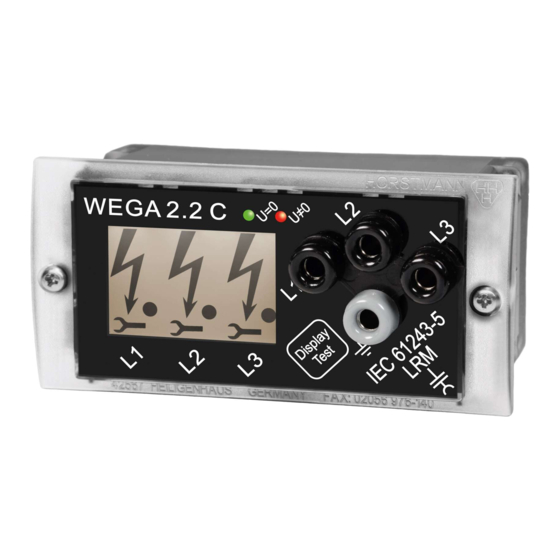
3. Design Housing: The integrated voltage detecting system WEGA 2.2 is located in a plug-in housing for panel mount (for dimensions see drawing) suitable for a panel cut-out size of 92 x 45 mm. The LCD display, the display test button and the three-phase LRM interface are located on the front panel. A removable plug serves to protect the jacks against dust and corrosion. -
Page 5: Mechanical Characteristics
LRM system. Distance between sockets 14mm, dia. 4mm 4.3 Remote indication The remote indication signals are fed out via a 6-pole plug-in connection on the rear side of the WEGA 2.2 device (see picture 2). Data of the relays: Type DSP1-DC12V... -
Page 6: Illustration Of Connection Points
Instructions for Use 4.4 Illustration of connection points The following connections are located on rear side (see picture 2): Picture 2: Connection points on rear side of the WEGA 2.2 4-pole flat connector: L1, L2, L3 Connections for the capacitive taps of the switchgear... -
Page 7: Voltage Testing
The integrated WEGA 2.2 voltage detecting system is designed for continuous operation. Due to this feature the WEGA 2.2 provides continuous voltage testing in the switchgear unit into which it has been installed displaying the „Voltage Present“ condition by illuminated arrow and dot symbols. -
Page 8: Monitoring Of Auxiliary Voltage
7. Maintenance Ensure that the integrated WEGA 2.2 voltage detecting systems are kept in a clean and dry environment, apart from that they do not require any maintenance. After having carried out a phase comparison or a function test the user must take care that the protection cap is reattached to the sockets of the LRM interface.