
Summary of Contents for zebris PDM
- Page 1 Measuring System for Pressure Distribution Measurement PDM/PDM mobile Specifications and Operating Instructions zebris Medical GmbH REF 79010135 Text-Release: 03/01/2019...
-
Page 2: Table Of Contents
Specification SYNC Interface ....................15 3.5.2 Synchronization of Video Recordings ..................16 3.5.3 Infrared synchronization with zebris DAB-Bluetooth (EMG) ............. 17 3.5.4 Connection of two PDM-L Platforms (Inter-PDM IR-SYNC) ............. 18 VIDEO-MODUL ..........................19 SYNCC ..........................19 SYNCL ........................20... - Page 3 ....................... 41 LEANING AND DISINFECTION 6.4.1 Cleaning ............................ 41 6.4.2 Manual Disinfection ........................41 ........................... 42 ISPOSAL 6.5.1 Packaging ..........................42 6.5.2 Disposal of electronics ......................42 zebris Medical GmbH PDM/PDM mobile Technical Data and Operating Instructions Page 3/42...
-
Page 4: Introduction
Please always provide the serial number of the product for inquiries! In order to facilitate the readability of the text, further on instead of PDM/PDM mobile the term PDM-System is used. Nevertheless, if not noted otherwise, all information is valid for both versions. -
Page 5: Structure Of The Pdm System User Manual
The measuring system PDM consists of the force distribution measuring sensor technolo- gy as well as the corresponding application software including a PC. Therefore, the user manual of the PDM measuring system consists of several parts: Part 1 - PDM technical specifications and user manual Part 2 - User manual for the zebris FDM application software Part 3 - User manual of the accessories, like e.g. -
Page 6: Symbols Used
This symbol shows that pursuant to the Directive on Waste Elec- trical and Electronic Devices (2012/19/EU) and national legislation, a product cannot be disposed of via the household waste Refer to instructions for use. Item Number Serial Number zebris Medical GmbH PDM/PDM mobile Technical Data and Operating Instructions Page 6/42... -
Page 7: Safety
2 Safety 2.1 Environmental conditions PDM Measuring Systems are suitable for application in dry interiors with level ground such as those in hospitals, doctors' surgeries and laboratories. Temperature 10°C to 40°C Relative humidity 30% to 70%, non condensing Air pressure... -
Page 8: User Obligations
The set-up room corresponds to the given environmental conditions of the measur- ing system and the valid installation regulations. The PDM system including accessories is connected to the mains socket with a pro- tective grounding conductor and is operated with the correct mains voltage. -
Page 9: General Safety Instructions
We also point out that if any changes are made to this certified device or its accessories without the prior written consent of zebris, your legal right to operate the device will be nullified. zebris Medical GmbH... -
Page 10: Product Description
User Manual for PDM Platform, accessories and zebris FDM software 3.2 Technical specifications 3.2.1 PDM Sensor The sensors of the different PDM system only vary in size of the measuring area, the number of single sensors included in the sensor module and the supported sampling fre- quency. -
Page 11: Pdm-Platform Types
542 x 339 mm (L x B) ⅓ Inch |1,4 Sensors / cm² ⅓ Inch |1,4 Sensors / cm² Resolution PC Interface USB 2.0 USB 2.0 / Bluetooth zebris Medical GmbH PDM/PDM mobile Technical Data and Operating Instructions Page 11/42... - Page 12 1220 x 474 mm (L x B) ⅓ Inch |1,4 Sensors / cm² ⅓ Inch |1,4 Sensors / cm² Resolution PC Interface USB 2.0 USB 2.0 / Bluetooth Inter-PDM IR-SYNC zebris Medical GmbH PDM/PDM mobile Technical Data and Operating Instructions Page 12/42...
-
Page 13: Controls And Connectors
All cable connections between platform and PC will be established by the connector box located at the bottom of the platform. Battery Switch SYNC (Video) USB Socket (mini B) Power Supply zebris Medical GmbH PDM/PDM mobile Technical Data and Operating Instructions Page 13/42... -
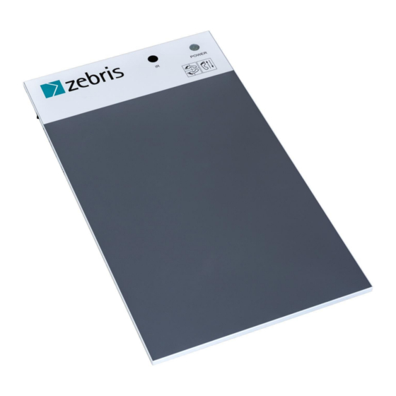
Page 14: Status Indicator Led
Platform ready for measurement, flashes NO USB connection with PC. Platform ready for measurement, USB connection with PC established Yellow / Battery Charging (PDM mobile only) flashes Battery is charging Orange / Measurement on / off Measurement is in progress... -
Page 15: Zebris Sync
3.5 zebris SYNC The zebris SYNC is the standard solution for the synchronization of the PDM-System with zebris camera and lighting systems. 3.5.1 Specification SYNC Interface Connection will be set up by a 3.5 mm stereo jack. 2 Pins: Output Video-SYNC... -
Page 16: Synchronization Of Video Recordings
3.5.2 Synchronization of Video Recordings The Sync socket provides synchronization of platform measurements and videos record- ed with zebris SYNCCam or SYNCLightCam available as accessories. For connection of SYNCCam or SYNCLightCam the Video Sync-Control Cable is required: REF-No 21030316 / Video Sync-Control Cable,... -
Page 17: Infrared Synchronization With Zebris Dab-Bluetooth (Emg)
3.5.3 Infrared synchronization with zebris DAB-Bluetooth (EMG) For synchronizing the PDM system with the zebris DAB-Bluetooth the optionally available IR interface which can be integrated within the platform housing is required. PDM platform and DAB-Bluetooth are synchronized automatically as soon as both devices have been switched on and a measurement is started. -
Page 18: Connection Of Two Pdm-L Platforms (Inter-Pdm Ir-Sync)
3.5.4 Connection of two PDM-L Platforms (Inter-PDM IR-SYNC) Two platforms of type PDM-L can be coupled (Master – Slave) in order to double usable walking range. For this purpose an infrared interface (Inter-PDM IR-SYNC) is integrated in the housing at the end of each platform. -
Page 19: Video-Modul
4 Video-Modul 4.1 SYNCCam The SYNCCam is an accessory of the PDM system and perfectly adapted to be used in combination with the force distribution measurement. All adjustments of the camera are carried out via hardware setup integrated to the zebris FDM Software. The camera is con- nected to the PC by a USB cable of type A-B included within the shipment. -
Page 20: Synclightcam
4.2 SYNCLightCam The SYNCLightCam is an accessory of the PDM system and perfectly adapted to be used in combination with the force distribution measurement. All adjustments of the camera are carried out via hardware setup integrated to the zebris FDM Software. The camera is con- nected to the PC by a USB cable of type A-B included within the shipment. - Page 21 SYNC Mode Switch Status-LED In order to maintain undisturbed transmission of the video signal it is mandatory to use high quality USB cables. Please, only use cables supplied or recommended by zebris for NOTE connecting SYNCCam and PC. zebris Medical GmbH...
- Page 22 40 W Mains Lead Plug Adapter SYNC Socket Characteristics Pin Assignment ESD - protected, voltage reversal proof input Input resistance: 38 k (AC) Signal-Level: Trigger Level: 15 mV zebris Medical GmbH PDM/PDM mobile Technical Data and Operating Instructions Page 22/42...
-
Page 23: Led Video Lights (Synclight / Synclight Plus)
The LED video lights SYNCLight and SYNCLight plus are accessories of the PDM sys- tem and perfectly adapted for use in combination with zebris SYNCCam as well as the force distribution measurement. -
Page 24: Synclight
4.3.1 SYNCLight If the synchronization signal from SYNC of the PDM Plattform is connected to the VIDEOSYNC socket the SYNCLight will be automatically turned on and off when a meas- urement is started or stopped. In order to use the synchronization set the SYNC Mode switch to position SYNC. At posi- tion CONT the SYNCLight is switched on permanently. -
Page 25: Synclight Plus
4.3.2 SYNCLight plus The SYNCLight plus supports the zebris VIDEOSYNC as well as more complex synchro- nization modes that may be required for use of industrial cameras. In order to use the synchronization modes set the SYNC-Mode switch to position SYNC. -
Page 26: Power Supply Unit Synclights
LEMO- Part No. The SYNC IN is the standard synchronization FGA.00 303.CLADxxxx tool (zebris SYNC) of all zebris measuring sys- tems and intended to be used to synchronize the lighting system with the measuring signal of other zebris measuring systems (e.g. CMS). - Page 27 Value. Begin of Illumination Timing Properties when Camera Trigger Input switching the Light OFF: No Delay (0µS) No Delay! No adjustment of Trigger-Output necessary! End of Illumination zebris Medical GmbH PDM/PDM mobile Technical Data and Operating Instructions Page 27/42...
-
Page 28: Replacement Parts Pdm System
PC 21030152 Bluetooth USB-Stick with Plug & Play functionality 4.5 Accessoires PDM-System REF- No. Description Illustrations 01540191 SYNCCam Camera with USB-Cable, synchronization- cable, tripod, inclusive software extension zebris Medical GmbH PDM/PDM mobile Technical Data and Operating Instructions Page 28/42... - Page 29 Mains adapter 110W / 24V DC, Supports up to 3 SYNC Light plus. 01850011 SYNCLight plus Adapter Cable for Master-Slave connection of up to 3 SYNCLight plus, length 1m zebris Medical GmbH PDM/PDM mobile Technical Data and Operating Instructions Page 29/42...
-
Page 30: Operation Of The Pdm System
5 Operation of the PDM System 5.1 Set up the measuring System For the commissioning of the PDM platform the suitable power supply, a USB cable type A-mini B as well as the installation CD with the zebris FDM software are necessary. All components are included in the scope of delivery of the PDM measuring system. -
Page 31: Connection Of The Measuring System To Mains Supply
5.2 Connection of the measuring system to mains supply For the connection of the PDM platform with the mains, connect the power supply with the mains socket and the power socket in the connector compartment. Exclusively use the power supply unit approved by zebris for the operation of the PDM platform, which is suitable for the power sup- ply of your platform. - Page 32 Damaged power sup- plies, cables or connection sockets immediately must be replaced WARNING by a person authorised to do so. zebris Medical GmbH PDM/PDM mobile Technical Data and Operating Instructions Page 32/42...
-
Page 33: Anschluss An Den Pc
5.3 Anschluss an den PC As a rule, the measuring system PDM is supplied together with a computer. If the system is to be operated using other computers or components, the user must then inquire wheth- er the intended coupling guarantees the necessary safety for the test person, the operator and the surroundings by consulting the manufacturer, the authorized zebris sales partner or by asking a specialist. -
Page 34: Closing The Safety Lock Of The Plug Tray
Now the measuring system is ready for us. A measurement is controlled completely by the zebris FDM software. Before starting and in case of any doubts in use of the software please thoroughly read the user manual of the zebris FDM software. -
Page 35: Connection Of The Platform Via Bluetooth Interface (Mobile Only)
“Settings“ under the section “Services“, so that the follow- ing system configuration information is read out. In addition, the “COM port” for the PDM mobile to which the device is connected has to be selected within the device settings. This one can be found, as described under “PC settings with PDM mobile, in the system configuration. -
Page 36: Switch The Pdm Platform On/Off
Windows operating system and shut down the PC. Then disconnect the power supply unit of the PDM platform from mains supply. To switch off the battery of PDM mobile set the battery switch located on the left hand side of the platform to position O. -
Page 37: Recommendations For Recording Data
1,20m. We recommend a distance of about 4m from start to PDM platform and no less than 3m behind. With such a walking stage it is easier to measure normal walking without acceleration or deceleration. -
Page 38: Control Measures, Preparation, Disposal
The maintenance of the device or its accessories, going beyond the procedures de- scribed in this user manual, must exclusively be carried out by zebris Medical GmbH or a person who has been explicitly authorized by zebris to do this. -
Page 39: Checking The Pdm Platform
6.2 Checking the PDM Platform 6.2.1 Control measures The correct measuring function of the PDM Platform must be checked at regular intervals to ensure that the measuring system is functioning properly. WARNING Should any damage to the measuring surface become evident (e.g. something fell hard on the measuring surface), no further measurements must be taken. -
Page 40: Troubleshooting
FDM software. NOTE Checklist for the reception of error messages In order to support you the best way possible in case of malfunction of your PDM measuring system, our service employees need the following information: NOTE ... - Page 41 WARNING In order to demonstrate that disinfection was successfully done, it is recommended to put up a sign on the platform, saying “disinfected”. NOTE zebris Medical GmbH PDM/PDM mobile Technical Data and Operating Instructions Page 41/42...
- Page 42 6.5 Disposal 6.5.1 Packaging All transport packaging delivered by zebris can be recycled within Ger- many via the local recycling depots. In order to provide the reuse of the recyclable material contained in the packaging, the zebris Medical GmbH takes part in the dual ZENTEK system that takes over the proper disposal of packaging.