Eaton Crouse Hinds Series Instruction Manual
Hide thumbs
Also See for Crouse Hinds Series:
- Instruction manual (114 pages) ,
- Operating instructions manual (44 pages) ,
- Technical manual (32 pages)

Related Manuals for Eaton Crouse Hinds Series


Summary of Contents for Eaton Crouse Hinds Series
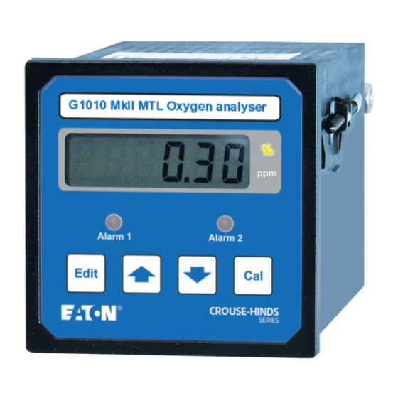
- Page 1 Instruction manual January 2017 MTL gas analysers & systems INM MTL 130-0116 Rev 14 G1010 MkII MTL oxygen analysers...
- Page 2 DECLARATION OF CONFORMITY A printed version of the Declaration of Conformity has been provided separately within the original shipment of goods. However, you can find a copy of the latest version at - http://www.mtl-inst.com/certificates INM MTL 130-0116 Rev 14...
-
Page 3: Table Of Contents
CONTENTS DECLARATION OF CONFORMITY ............ii INTRODUCTION . - Page 4 THIS PAGE IS LEFT INTENTIONALLY BLANK INM MTL 130-0116 Rev 14...
-
Page 5: Introduction
INTRODUCTION The Oxygen Analysers in this range are microprocessor controlled and provide a performance and a range of features without parallel for analysers of this type and cost. The G1010 and G1010R have a display that autoranges over a span of approximately 5 decades, (depending on the model) the alarms and analogue output are user programmable. -
Page 6: Specification
SPECIFICATION Display Multi-digit LCD - character height 12.7mm Display and output ranges G1010 and G1010R 1. E cell model - Display range 0.1% to 100.0%. Resolution: 0.1% from 10% to 100%; 0.01% below 10%. 2. N cell model - Display range 100ppm to 50%. Resolution: 0.1% from 10% to 50%;... -
Page 7: Sample Temperature
Sample temperature –5 to +40°C (non condensing) Sample connections Inlet and outlet: captive seal compression fittings suitable for 0.25 inch (or 6mm) o/d tube Speed of response T90 is variable depending on sensor and concentration and is approximately 3 secs at % levels and 20 secs at ppm levels. -
Page 8: Installation
INSTALLATION Unpacking and visual checking Take all standard precautions when opening packages. In particular avoid the use of long bladed cutters. Search packing before discarding it and make sure that all of the components are removed. Check that all pipe connections have captive seal nuts. Mounting Chose a site where the ambient temperature will remain between the limits of the instrument (see “Environmental conditions”... -
Page 9: Sample Connections
Mains Cell Alarm 1 Alarm 2 An. O/P C NC NO C NC NO 11 12 13 1 2 3 4 5 6 7 8 9 10 11 12 13 120-0024 120-0023 Figure 2 - Instrument connections 3.4.1 Installation requirements for EMC To ensure compliance with the European EMC directive, certain installation precautions are necessary as detailed here. - Page 10 Figure 3 - G1010 sampling system INM MTL 130-0116 Rev 14...
- Page 11 Figure 4 - G1010R sampling system INM MTL 130-0116 Rev 14...
- Page 12 Figure 5 - G1010Tx & TxX sampling system INM MTL 130-0116 Rev 14...
-
Page 13: Cell Characteristics
Cell characteristics Air (20.9%) 1ppm 10ppm 100ppm 1000ppm 100% Oxygen Concentration (logarithmic scale) Suitability depends Suitable Unsuitable upon application Figure 6 - G1010 Measurement range versus cell type 3.6.1 E cells These are partial pressure cells and as such are affected by changes in atmospheric pressure. -
Page 14: Cell Installation
Cell installation Refer to “Replacing/connecting the cell” on page 18. Alarm contacts NOTE The relay operation and labelling that refers to ‘Normal’, relates to process Normal and not the electrical rest position of the relays. In process Normal the relays are energised. -
Page 15: Commissioning
COMMISSIONING Applying power When the analyser is fully connected, it may be powered. When power is applied, the analyser briefly sets the alarms and analogue output to the fault condition – both alarms on and analogue output at approximately 115% (~5.6V or 22.5mA) – then automatically enters ‘normal’... -
Page 16: Applying The Sample
4.2.4 ANALOGUE OUTPUT - Top scale value When the Edit button is pressed following Alarm 2 hysteresis entry, the display will show “EPxxxx”, where “xxxx” is the oxygen concentration at which the analogue output (0 to 5V or 4 to 20mA) is at top scale. Neither alarm LED is flashing. Press arrow buttons to change the value of oxygen concentration equivalent to the top scale value of the analogue output. -
Page 17: Error Messages
Error messages Display Priority Occurs Description Corrective action HELP 4 During start up User calibration Press the UP ( ) key. Factory default and/or setup data values are loaded for alarms, o/p is corrupt. range, cell calibration etc. After a few seconds the instrument will drop into the EDIT menu. - Page 18 Figure 7 - Cell response times INM MTL 130-0116 Rev 14...
-
Page 19: Maintenance And Calibration Checks
MAINTENANCE AND CALIBRATION CHECKS WARNING Disable all analyser-dependent plant control functions before commencing calibration and maintenance procedures. 2. Some of the procedures described when replacing/connecting a cell assume that the escape of the sample into the atmosphere will not constitute any sort of hazard such as asphyxiation, flammability etc. It is the responsibility of the user/operator to ensure this. - Page 20 5.2.3 Calibration of instruments fitted with ‘N’ and ‘E’ Type cells 5.2.3.1 Calibration gas level For optimum accuracy it is best to calibrate with a gas of the same composition and oxygen concentration as the normal sample. Refer to section 4.6.2 if calibrating an ‘N’...
- Page 21 5.2.4.2 Calibrating instruments typically measuring less than 50ppm oxygen For these analysers, the ‘zero’ or low point of the analyser should be set using a gas of similar concentration to the typical in-service concentration. Flow the calibration gas through the analyser and wait for the reading to stabilize. If the reading is the same as the concentration of the calibration gas, no adjustment is necessary, and the analyser may be put back in normal service.
-
Page 22: Cell Replacement - Overview
Cell replacement - overview Before proceeding, identify which cell is to be replaced, then read and fully understand the following appropriate procedure. For best accuracy it is necessary to re-calibrate the instrument following a cell change. The calibration procedure depends on the type of cell fitted to the instrument. See section 6.2 for additional information on calibration before proceeding. - Page 23 5.3.1.2 Replacing E cells E cells are shipped with the sample port open and the leads insulated to prevent them touching. The insulation sleeve must be removed before the signal leads are connected to the input of the instrument following the setting of the cells zero offset.
-
Page 24: Spares And Repairs
SPARES AND REPAIRS Ordering parts The replacement cell is the only user serviceable part. If any failure occurs, the instrument should be returned to your local MTL Gas sales office for repair. When ordering spare cells or raising queries on the instrument, it is important that the serial number or job number, is quoted. - Page 25 THIS PAGE IS LEFT INTENTIONALLY BLANK INM MTL 130-0116 Rev 14...
- Page 26 MTL Instruments GmbH, Heinrich-Hertz-Str. 12, 50170 Kerpen, Germany UNITED ARAB EMIRATES Cooper Industries/Eaton Corporation Tel: +49 (0)22 73 98 12 - 0 Fax: +49 (0)22 73 98 12 - 2 00 Office 205/206, 2nd Floor SJ Towers, off. Old Airport Road, E-mail: csckerpen@eaton.com...