Table of Contents
Advertisement
Available languages
Available languages
Quick Links
CONTROLLER ATTACHMENT STAND
BKM-37H
安全のための注意事項を守らないと、火災や
人身事故になることがあります。
このインストレーションマニュアルには、事故を防ぐための重要な注意事
項と製品の取り扱いかたを示してあります。このインストレーションマ
ニュアルをよくお読みのうえ、製品を安全にお使いください。お読みに
なったあとは、いつでも見られるところに必ず保管してください。
INSTALLATION MANUAL
[Japanese/English/French/German/Italian/Spanish]
[Simplified Chinese/Traditional Chinese/Korean]
1st Edition (Revised 5)
Advertisement
Chapters
Table of Contents

Related Manuals for Sony BKM-37H


Summary of Contents for Sony BKM-37H
- Page 1 CONTROLLER ATTACHMENT STAND BKM-37H 安全のための注意事項を守らないと、火災や 人身事故になることがあります。 このインストレーションマニュアルには、事故を防ぐための重要な注意事 項と製品の取り扱いかたを示してあります。このインストレーションマ ニュアルをよくお読みのうえ、製品を安全にお使いください。お読みに なったあとは、いつでも見られるところに必ず保管してください。 INSTALLATION MANUAL [Japanese/English/French/German/Italian/Spanish] [Simplified Chinese/Traditional Chinese/Korean] 1st Edition (Revised 5)
- Page 2 日本語 安全のために 警告 警告表示の意味 このインストレーションマニュア ルおよび製品では、次のような表 示をしています。表示の内容をよ 下記の注意を守らないと、 く理解してから本文をお読みくだ 火災 感電 死亡 大けが さい。 や により や に つながることがあります。 この表示の注意事項を守らないと、 油煙、湯気、湿気、ほこりの多い場所では設 火災や感電などにより死亡や大け 置・使用しない がなど人身事故につながることが 上記のような場所で設置・使用すると、火災や感電の原因と あります。 なります。取扱説明書に記されている使用条件以外の環境で の設置・使用は、火災や感電の原因となります。 モニターとスタンドの間に指を挟まない この表示の注意事項を守らないと、 挟み込まれると、けがの原因となることがあります。 事故によりけがをしたり周辺の物 品に損害を与えたりすることがあ ります。 注意を促す記号 組み立ての際には、モニターの電源を切って 電源プラグを抜く モニターの電源を接続したまま、本スタンドとの組み立てを 行うと、モニターと本スタンドに電源コードをはさみ、感電 の原因となることがあります。組み立ての際にはモニターの 電源を切り、電源プラグを抜いてください。...
- Page 3 注意 指定された接続ケーブルを使 う この取扱説明書に記されている接続ケー ブルを使わないと、火災や故障の原因と なることがあります。 組み立てる際は必ず付属のネ ジを使う 違うネジを使用すると、ゆるんだり、外 重いモニターは 2人以上で開 れたりしてけがの原因となることがあり 梱・運搬する ます。 モニターは、見た目より重量がありま 運搬時は、電源コードや接続 す。開梱や運搬は、けがや事故を防ぐた め、必ず 2 人以上で行ってください。1 コードをはずす 人で行うと、腰を痛めることがありま 転倒などによるけがの原因となることが す。 あります。 組立て作業は 2人以上で行う 指定以外の機器には使用しな モニターとコントロールユニットを連結 い する時は、2 人以上で行ってください。 1 人で行うと、腰を痛めたり、けがの原 指定以外の機器を取り付けると、落下、 因となることがあります。 転倒してけがの原因となることがありま す。 組み立て作業時に手や指をは さまない モニターの角度調整は、必ず 天面と底面をもって操作する...
- Page 4 製品の上に乗らない、重いも のを載せない 倒れたり、落ちたり、壊れたりして、け がの原因となることがあります。 改造しない 改造すると強度が低下し、モニターが転 倒してけがの原因となることがありま す。 シャープエッジには素手で触 れない 機器の開梱、運搬、設置、分解の際はけ がを防ぐため保護手袋を着用してくださ い。 サイドカバーを付けて使用す る サイドカバーを付けずに使用すると可動 部に指を挟みこみけがの原因となること があります。 スタンド使用時には必ずスタ ンドのチルト調整ネジを締め て固定する モニターが急に動いたりしてけがの原因 となることがあります。 注意...
-
Page 5: Table Of Contents
目次 概要...........................6 特長 .......................6 部品構成 ......................6 組み立て ........................7 モニターとコントロールユニットを連結する..........7 角度を変える ....................10 モニターと連結する ..................10 高さを低くする ...................11 お使いになる前に、必ず動作確認を行ってください。故障その他に伴う 営業上の機会損失等は保証期間中および保証期間経過後にかかわらず、 補償はいたしかねますのでご了承ください。 目次... -
Page 6: 部品構成
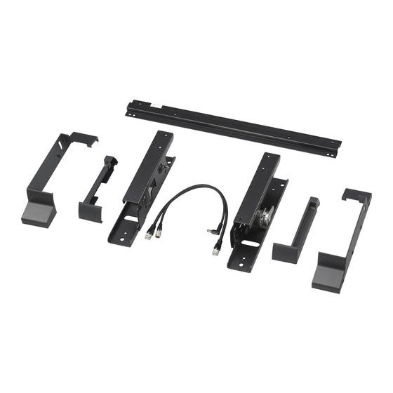
チルトユニットを取り付けたとき 概要 特長 BKM-37H は、BVM-E251 にモニターコントロールユニット BKM-17R を取り付け可能なチルトスタンドです。 モニターとコントロールユニットを連結可能 モニターとコントロールユニット BKM-17R を連結すること ができます。また、コントロールユニットを取り付けずに、 単位:mm モニターのチルトスタンドとしても使用可能です。 チルトユニットを取りはずしたとき モニターの角度変更が可能 前方向に 5°、後ろ方向に 10°までの範囲でモニターの角 度を変えることができます。 単位:mm 部品構成 BKM-37H は以下の部品で構成されています。組み立てを始 める前に、部品がすべてそろっていることをお確かめくださ 高さ変更が可能 い。 チルトユニットを取りはずすことによって、スタンド取り付 スタンド(右)× 1 け時の高さを低くすることができます。 ◆ チルトユニットの取りはずしかたは、 「 高さを低くする」 (11 ページ)をご覧ください。 スタンド(左)× 1 リアステー× 1... -
Page 7: 組み立て
カバー(上) (右)× 1 組み立て カバー(上) (左)× 1 モニターとコントロールユニットを連 結する スタンドを使ってモニターとコントロールユニットを連結す ることができます。 カバー(下) (右)× 1 コントロールユニット底面の足 5 個をはずす。 カバー(下) (左)× 1 ジョイント× 2 コントロールユニット コントロールユニットの両側面にネジ B(4 × 8)4 本を ネジ A(3 × 8)× 12 使ってスタンド(左)およびスタンド(右)を取り付け る。 各スタンドは、ネジ B を 2 本ずつ使って固定します。 ネジ... - Page 8 モニター底面の足 4 個と、 モニター後面のネジ (左右 1 か スタンドを付けたコントロールユニットの上にモニター 所ずつ)をはずす。 を載せ、リアステーの位置をネジ穴に合わせて、ネジ B (4 × 8)4 本を使って固定する。 左右にある突起部をあわせてください。 ネジ B 突起部 モニター後面 コントロール ユニット ご注意 モニターを柔らかい布などの上に水平に置いてくださ スタンド(右) い。 モニターの上にリアステーを載せ、ネジ B(4 × 8)2 本 スタンド(右)にジョイントを載せ、ネジ B(4 × 8)3 を使って固定する。 本を使ってスタンド(右)とモニター右後面にジョイン ネジ B トを固定する。 リアステー ネジ B ジョイント スタンド(右) 組み立て...
- Page 9 スタンド(左)にジョイントを載せ、ネジ B(4 × 8)3 ネジ A(3 × 8)4 本ずつを使って、カバー(下) (左)お 本を使ってスタンド(左)とモニター左後面にジョイン よびカバー(下) (右)をスタンド(左)とスタンド トを固定する。 (右)に取り付ける。 チルトユニット付きのとき カバーを上からかぶせます。 ネジ B ジョイント スタンド(左) ネジ A カバー(下) ネジ A(3 × 8)2 本ずつを使って、カバー(上) (左)お よびカバー(上) (右)を取り付ける。 チルトユニットをはずしたとき まずカバーの前部をはめ、次に後ろを反らしながらはめ 込みます。 ネジ A カバー(上) ネジ A カバー(下) 組み立て ...
-
Page 10: 角度を変える
付属の接続ケーブルを、コントロールユニット後面の 角度を変える DC 12V 端子および LAN(10 / 100)端子に接続する。 スタンド(左)およびスタンド(右)のカバーの奥にあるチ ご注意 ルト調整ネジをゆるめ、上部と底面を持って傾けます。調整 DC 12V 端子には、DC ケーブル(L 型)を接続してく 後は必ずチルト調整ネジをしっかり締めてください。 ださい。 接続ケーブルのコネクターを、モニター後面の DC 12V OUT 端子および LAN(10 / 100)端子に接続する。 チルト調整ネジ ご注意 DC 12V OUT 端子にケーブルをつなぐときは、ケーブ ル先端の形と DC 12V OUT 端子の形を合わせるように モニターと連結する して差し込んでください。 コントロールユニットを取り付けなくても、このスタンドを モニターに取り付けて使用できます。 (10 / 100) 組み立てかたは、 「モニターとコントロールユニットを連結 端子 する」の... -
Page 11: 高さを低くする
スタンド(左)およびスタンド(右)に、付属のネジ C 高さを低くする (5 × 10)1 本ずつを取り付けたあと、チルト調整ネジ を締める。 チルトユニットを取りはずすことによって、スタンド取り付 け時の高さを低くすることができます。モニターとコント ロールユニットを連結する前に、スタンド(左)およびスタ ンド(右)からチルトユニットを取りはずしてください。 ご注意 チルトユニットを取りはずすとモニターの角度調整はできな チルト調整ネジ くなります。 ネジ C スタンド(左)およびスタンド(右)のチルト調整ネジ をゆるめる。 もとの高さに戻すには 上記と逆の手順でチルトユニットを取り付けます。 チルト調整ネジ ご注意 取りはずしたネジは、保管しておいてください。 チルトユニット スタンド(左)およびスタンド(右)からそれぞれ7本 のネジをはずす。 スタンド(左)およびスタンド(右)からチルトユニッ トを取りはずす。 組み立て ... - Page 12 Joining the Monitor ..............18 Lowering the Height..............18 Note Always verify that the unit is operating properly before use. SONY WILL NOT BE LIABLE FOR DAMAGES OF ANY KIND INCLUDING, BUT NOT LIMITED TO, COMPENSATION OR REIMBURSEMENT ON ACCOUNT OF THE LOSS OF...
-
Page 13: Precautions
The BKM-37H Controller Attachment Stand is a tilt stand attachment stand and this may lead to electric shock. for joining a BVM-E251 and a BKM-17R Monitor Control •... -
Page 14: Components
Unit: mm (inches) Screws B (4 × 8) (16) Components Screws C (5 × 10) (2) The BKM-37H consists of the following components. Make sure that you have all the components before beginning assembly. Stand (right) (1) Connecting cable (1) -
Page 15: Assembly
Remove the four legs from the bottom of the monitor Assembly and the screws on the left and right sides from the rear of the monitor. Joining the Monitor and the Control Unit You can join a control unit to a monitor using the attachment stand. - Page 16 Place the monitor on the control unit with the stands Place the joint on the left stand, and fix the left stand on attached. Attach the monitor to the stands using four the rear (left side) of the monitor using three screws B screws B (4 ×...
-
Page 17: Tilting The Monitor
When the tilt unit is removed Plug the connecting cable into the DC 12V OUT and First put the front of the cover over the stand, then fit LAN (10/100) connectors on the rear panel of the the back of the cover while bending it outward. monitor. -
Page 18: Joining The Monitor
Remove the tilt units from the right stand and left Joining the Monitor stand. Even when the control unit is not joined to the monitor, the attachment stand can be attached to the monitor alone. For assembly, see steps 3 (page 15) to 9 (page 16) of “Joining the Monitor and the Control Unit”. - Page 19 Réglage de la hauteur vers le bas..........25 Remarque Vérifiez toujours que l’appareil fonctionne correctement avant l’utilisation. Sony n’assumera pas de responsabilité pour les dommages de quelque sorte qu’ils soient, incluant mais ne se limitant pas à la compensation ou au remboursement, à...
-
Page 20: Précautions
Sinon, le câble risque d’être coincé entre le moniteur et le socle de montage et provoquer une électrocution. Le socle de montage du contrôleur BKM-37H est un socle • Assemblez le moniteur et l’unité de commande à l’aide incliné permettant d’assembler un BVM-E251 et une unité... -
Page 21: Composants
Unité : mm (pouces) Vis B (4 × 8) (16) Composants Vis C (5 × 10) (2) Le BKM-37H est constitué des composants suivants. Vérifiez que vous disposez de tous les composants avant de commencer le montage. Socle (droit) (1) Câble de connexion (1) -
Page 22: Montage
Retirez les quatre pieds de la base du moniteur et les vis Montage du socle droit et du socle gauche de l’arrière du moniteur. Assemblage du moniteur et de l’unité de commande Vous pouvez assembler une unité de commande et un moniteur à... - Page 23 Placez le moniteur sur l’unité de commande avec les Placez le joint sur le socle gauche, puis fixez le socle socles fixés. Fixez le moniteur sur les socles à l’aide de gauche à l’arrière (côté gauche) du moniteur à l’aide de quatre vis B (4 ×...
- Page 24 Fixez le capot inférieur droit et le capot inférieur Connectez le câble de connexion fourni aux gauche sur les socles à l’aide de quatre vis A (3 × 8) connecteurs DC 12V et LAN (10/100) sur le panneau pour chacun. arrière de l’unité...
-
Page 25: Inclinaison Du Moniteur
Desserrez les vis d’inclinaison sur le socle droit et le Inclinaison du moniteur socle gauche. Desserrez la vis d’inclinaison située à l’intérieur du capot du socle droit et celle du socle gauche, puis inclinez le moniteur en tenant le haut et le bas du moniteur ou de Vis d’inclinaison l’unité... - Page 26 Réglage de la hauteur du socle de montage (vers le haut) Suivez les étapes 1 à 4 de la section « Réglage de la hauteur vers le bas » dans le sens inverse. Remarque Rangez soigneusement les vis que vous avez retirées pour pouvoir les utiliser ultérieurement.
- Page 27 Monitor anbauen ...............33 Einbauhöhe verringern..............33 Hinweis Bestätigen Sie vor dem Gebrauch immer, dass das Gerät richtig arbeitet. SONY KANN KEINE HAFTUNG FÜR SCHÄDEN JEDER ART, EINSCHLIESSLICH ABER NICHT BEGRENZT AUF KOMPENSATION ODER ERSTATTUNG, AUFGRUND VON VERLUST VON AKTUELLEN ODER ERWARTETEN PROFITEN DURCH FEHLFUNKTION DIESES GERÄTS ODER AUS...
-
Page 28: Sicherheitsmaßnahmen
Verbindung von Monitor und Steuergerät vermeiden. • Die Standhalterung auf einem stabilen Tisch aufstellen. Die BKM-37H verbindet den Monitor und das Steuergerät Wird die Standhalterung auf einer unebenen oder BKM-17R. Die Standhalterung kann auch als geneigten Oberfläche aufgestellt, besteht die Gefahr, Neigungshalter für den Monitor verwendet werden, wenn... -
Page 29: Komponenten
Schrauben A (3 × 8) (12) Einheit: mm Schrauben B (4 × 8) (16) Komponenten Schrauben C (5 × 10) (2) Die BKM-37H besteht aus folgenden Komponenten. Vor Beginn der Montage sicherstellen, dass alle Komponenten vorhanden sind. Anschlusskabel (1) Aufnahme (rechts) (1) -
Page 30: Zusammenbau
Die vier Füße an der Unterseite des Steuergeräts Zusammenbau abbauen und die Schrauben auf der linken und rechten Seite von der Rückseite des Monitors entfernen. Monitor und Steuergerät zusammenbauen Mit der Standhalterung kann ein Steuergerät an den Monitor angebaut werden. Die fünf Füße an der Unterseite des Steuergeräts abbauen. - Page 31 Monitor mit angebauten Standhalterungen auf dem Verbindungsstück auf die linke Standhalterung setzen Steuergerät anordnen. Monitor mit vier Schrauben B (4 und die linke Standhalterung mit drei Schrauben B (4 × 8) an Standhalterungen anbauen und dabei die × 8) an der Rückseite (linken Seite) des Monitors Position der Schraublöcher der hinteren Streben und befestigen.
- Page 32 Rechte untere Abdeckung und linke untere Abdeckung Schließen Sie das mitgelieferte Verbindungskabel an mit jeweils vier Schrauben A (3 × 8) an den die Anschlüsse DC 12V und LAN (10/100) an der Standhalterungen befestigen. Rückseite des Steuergeräts an. Bei angebautem Neigungshalter Hinweis Abdeckung von oben auf die Standhalterung setzen.
-
Page 33: Monitorneigung Einstellen
Neigungsschrauben an der rechten und linken Monitorneigung einstellen Aufnahme lösen. Neigungsschrauben im Inneren der rechten und linken Aufnahmeabdeckung lösen. Den gewünschten Neigungswinkel einstellen, dabei Monitor oben und Neigungsschraube Monitor- bzw. Steuergerät-Unterkante festhalten. Sicherstellen, dass die Neigungsschrauben nach Einstellung der Neigung wieder befestigt wurden. Neigungseinheit Jeweils sieben Schrauben aus der rechten und linken Aufnahme herausdrehen. - Page 34 Einbauhöhe vergrößern Schritte 1 bis 4 in „Einbauhöhe verringern“ in umgekehrter Reihenfolge ausführen. Hinweis Ausgebaute Schrauben für eine spätere Verwendung sorgfältig aufbewahren. Zusammenbau...
- Page 35 Nota Verificare sempre che l’apparecchio stia funzionando correttamente prima di usarlo. LA SONY NON SARÀ RESPONSABILE DI DANNI DI QUALSIASI TIPO, COMPRESI, MA SENZA LIMITAZIONE A, RISARCIMENTI O RIMBORSI A CAUSA DELLA PERDITA DI PROFITTI ATTUALI O PREVISTI DOVUTA A GUASTI DI QUESTO APPARECCHIO, SIA DURANTE IL PERIODO DI VALIDITÀ...
-
Page 36: Precauzioni
La base di fissaggio del controller BKM-37H è una base e ciò potrebbe causare una scossa elettrica. inclinabile per unire un BVM-E251 e un’unità di controllo •... -
Page 37: Componenti
Unità: mm Viti B (4 × 8) (16) Componenti Viti C (5 × 10) (2) Il BKM-37H consiste dei seguenti componenti. Accertarsi di disporre di tutti i componenti prima di avviare la procedura di montaggio. Cavo di collegamento (1) Base (lato destro) (1) -
Page 38: Montaggio
Rimuovere i quattro piedini dalla parte inferiore del Montaggio monitor e le viti sui lati sinistro e destro dalla parte posteriore del monitor. Fissaggio di monitor e unità di controllo È possibile fissare un’unità di controllo a un monitor usando la base di supporto. Rimuovere i cinque piedini dalla parte inferiore dell’unità... - Page 39 Posizionare il monitor sull’unità di controllo con le Posizionare il giunto sulla base di sinistra e fissarla basi fissate. Fissare il monitor alle basi usando quattro sulla parte posteriore (lato sinistro) del monitor usando viti B (4 × 8), regolando le posizioni dei fori delle viti tre viti B (4 ×...
-
Page 40: Inclinazione Del Monitor
Quando viene rimossa l’unità inclinabile Collegare il cavo di collegamento ai connettori DC Prima posizionare la parte anteriore del coperchio 12V OUT e LAN (10/100) sul pannello posteriore del sopra la base, quindi montare il retro del coperchio, monitor. piegandolo verso l’esterno. Nota Quando si collega il cavo al connettore DC 12V OUT, verificare di collegare il connettore del cavo nel... -
Page 41: Fissaggio Del Monitor
Rimuovere le unità inclinabili dalla base destra e Fissaggio del monitor sinistra. La base di supporto può essere fissata solo al monitor anche quando l’unità di controllo non è fissata al monitor. Per il montaggio, vedere i punti da 3 (pagina 38) a 9 (pagina 39) di “Fissaggio di monitor e unità... - Page 42 Nota Verifique siempre que esta unidad funciona correctamente antes de utilizarlo. SONY NO SE HACE RESPONSIBLE POR DAÑOS DE NINGÚN TIPO, INCLUYENDO PERO NO LIMITADO A LA COMPENSACIÓN O PAGO POR LA PÉRDIDA DE GANANCIAS PRESENTES O FUTURAS DEBIDO AL FALLO DE ESTA UNIDAD, YA SEA DURANTE LA VIGENCIA DE LA GARANTÍA O...
-
Page 43: Precauciones
Asegúrese de que la ubicación de instalación es El BKM-37H conecta el monitor y la unidad de control suficientemente resistente. BKM-17R. El soporte de fijación también se puede usar •... -
Page 44: Componentes
Unidad: mm Tornillos B (4 × 8) (16) Componentes Tornillos C (5 × 10) (2) El BKM-37H consta de los siguientes componentes. Asegúrese de disponer de todos los componentes antes de iniciar el montaje. Cable de conexión (1) Soporte (derecho) (1) -
Page 45: Montaje
Desmonte las cuatro patas de la parte inferior del Montaje monitor y los tornillos de los laterales izquierdo y derecho de la parte posterior del monitor. Conexión del monitor y la unidad de control Puede acoplar una unidad de control a un monitor mediante el soporte de fijación. - Page 46 Coloque la unidad de control con los soportes Coloque la unión en el soporte izquierdo y fije el montados en el monitor. Fije los soportes al monitor soporte izquierdo a la parte posterior (izquierda) del con los cuatro tornillos B (4 × 8) ajustando las monitor con tres tornillos B (4 ×...
- Page 47 Fije la cubierta inferior derecha y la cubierta inferior Conecte el cable de conexión suministrado a los izquierda a los soportes con cuatro tornillos A (3 × 8) conectores DC 12V y LAN (10/100) del panel en cada una. posterior de la unidad de control. Si la unidad de basculamiento está...
-
Page 48: Basculamiento Del Monitor
Afloje los tornillos de basculamiento del soporte Basculamiento del monitor derecho y el soporte izquierdo. Afloje el tornillo de basculamiento situado dentro de la cubierta del soporte derecho y el del soporte izquierdo y, a Tornillo de continuación, bascule el monitor sujetando la parte basculamiento superior del monitor y la parte inferior del monitor o la unidad de control. - Page 49 Elevación de la altura del soporte de fijación Siga los pasos del 1 al 4 de “Reducción de la altura” en orden inverso. Nota Guarde los tornillos desmontados en un lugar seguro para su uso en un futuro. Montaje...
- Page 50 机型名称:控制器安装支架 使用产品前请仔细阅读本书,并请妥善保管。 关于旧产品的处理 请不要将旧的产品与一般的生活垃圾一同弃置。 正确弃置旧的产品有助于避免对环境和人类健康造成 潜在的负面影响。 具体处理方法请遵循当地的规章制度。 目录 注意事项................51 概述..................51 功能 ..................51 部件 ..................52 组装..................53 连接监视器和控制单元 ............53 倾斜监视器 ................55 连接监视器 ................55 降低高度 .................. 56 注意 在使用前请始终确认本机运行正常。 无论保修期内外或基于任何理由, SONY 对任何损坏概不负责。由于本机故障造 成的现有损失或预期利润损失,不作 (包括但不限于)退货或赔偿。 目录...
-
Page 51: 注意事项
注意事项 概述 • 组装固定支座时,在拔出电缆前先关闭监视器电 功能 源。 如果在监视器电源开启的情况下安装固定支 座,电缆可能卡在监视器和固定支座之间,引发触 电危险。 BKM-37H 控制器固定支座是用于连接 BVM-E251 和 • 请在他人协助下连接监视器和控制单元,以免受 BKM-17R 监视器控制单元的倾斜支座。 伤。 • 将固定支座安装在稳固的桌面上。 如果将固定支座 连接监视器和控制单元 安装在摇摆不定或倾斜的表面上,监视器可能滑 落,致使人员受伤。 确保安装位置足够牢固。 BKM-37H 将监视器和 BKM-17R 控制单元连接在一 • 如果使用其它螺钉,可能因螺钉松开或掉出而导致 起。即使没有安装 BKM-17R,也可将固定支座用作 人员受伤。 监视器的倾斜支座。 • 不要将本固定支座安装到非指定设备上。 否则监视 器可能跌落,致使人员受伤。 倾斜监视器... - Page 52 护盖 (下部) (左侧) (1) 拆除倾斜装置时 接头 (2) 螺钉 A (3 × 8) (12) 单位: 毫米 螺钉 B (4 × 8) (16) 部件 螺钉 C (5 × 10) (2) BKM-37H 由以下部件组成。 开始组装前,确保部件齐全。 支座 (右侧) (1) 连接电缆 (1) 支座 (左侧) (1) 后撑条 (1) 概述...
-
Page 53: 连接监视器和控制单元
拆下监视器底部的四个支脚和监视器背面左右两 组装 侧的螺钉。 连接监视器和控制单元 您可以使用固定支座将控制单元连接到监视器。 拆下控制单元底部的五个支脚。 监视器背面 控制单元 注意 将监视器平放在软布上。 使用四颗螺钉 B (4 × 8) 将右支座和左支座安装到 控制单元的侧部。 将后撑条放在监视器上,并用两颗螺钉 B (4 × 8) 组装。 两个支座各用两颗螺钉 B。 螺钉 B 右支座 后撑条 左支座 螺钉 B 组装... - Page 54 将监视器放在安装了支座的控制单元上。使用四 将接头放在左支座上,用三颗螺钉 B (4 × 8) 固定 颗螺钉 B (4 × 8) 将监视器安装到支座上,并调整 监视器背面 (左侧)的左支座。 后撑条和控制单元的螺钉孔位置。 如图所示,将控制单元的突出部分放入后撑条的 孔中。 螺钉 B 接头 螺钉 B 支座 (左侧) 突出部分 分别用两颗螺钉 A (3 × 8) 将右上部护盖和左上部 护盖安装到支座。 控制单元 支座 (右侧) 将接头放在右支座上,用三颗螺钉 B (4 × 8) 固定 螺钉...
-
Page 55: 倾斜监视器
拆除倾斜装置时 将连接电缆插入监视器后面板上的 DC 12V OUT 和 先将护盖的前部放在支座上,然后将护盖的后部 LAN (10/100) 接口。 向外弯曲,同时将它装好。 注意 将电缆连接到 DC 12V OUT 接口中时,务必按正 确的方向将电缆的接头插入监视器上的 DC 12V OUT 接口。 LAN (10/100) 接口 DC 12V OUT 接口 螺钉 A 按正确的方向插 入接头。 下部护盖 将附带的连接电缆连接到控制单元后面板上的 DC 12V 和 LAN (10/100) 接口。 倾斜监视器... -
Page 56: 降低高度
将附带的螺钉 C (5 × 10) 分别紧固到两个支座,然 降低高度 后拧紧倾斜螺旋。 拆下右支座和左支座上预先安装的倾斜装置可以降低 固定支座的安装高度。 将控制单元连接到监视器之前 拆下倾斜装置。 注意 拆下倾斜装置后监视器将无法倾斜。 倾斜螺旋 松开右支座和左支座上的倾斜螺旋。 螺钉 C 提升固定支座的高度 按相反顺序执行 “降低高度”中的步骤 1 至 4。 倾斜螺旋 注意 妥善保管拆下的螺钉,以备后用。 倾斜装置 从右支座和左支座上分别拧出七颗螺栓。 从右支座和左支座上拆下倾斜装置。 组装... - Page 57 中文 在開始操作本裝置之前,請先仔細閱讀本手冊,並保 留本手冊以供日後參考。 目錄 使用前需知................58 概述..................58 功能 ..................58 組件 ..................59 組裝..................60 接合顯示器和控制元件 ............60 傾斜顯示器 ................63 接合顯示器 ................63 降低高度 ..................63 注意 在使用前請始終確認本機運行正常。 無論保修期內外或基於任何理由, SONY 對任何損壞概不負責。由於本機故障造 成的現有損失或預期利潤損失,不作 (包括但不限於)退貨或賠償。 目錄...
- Page 58 使用前需知 概述 • 當您組裝附接底座時,請先關閉顯示器電源,然後 功能 再拔下纜線。如果您在顯示器電源啟動時組裝附接 底座,纜線很可能會被卡在顯示器和附接底座之 間,而導致觸電。 BKM-37H 控制器附接底座是用於接合 BVM-E251 和 • 請另一個人協助您接合顯示器和控制元件,以避免 BKM-17R 顯示器控制元件的傾斜底座。 人員受傷。 • 請在穩固的桌面上安裝附接底座。如果在搖晃或傾 接合顯示器和控制元件 斜的表面上安裝附接底座,顯示器可能會掉落而使 您受傷。請確定進行安裝的位置夠穩固。 BKM-37H 可接合顯示器和 BKM-17R 控制元件。即 • 使用其他的螺絲可能會因螺絲鬆脫而造成人員受 使未附接 BKM-17R,此附接底座也可當成顯示器的 傷。 傾斜底座。 • 請勿將附接底座安裝在非指定的裝置上。否則,顯 示器可能會掉落而使您受傷。 傾斜顯示器 • 當傾斜顯示器時,請托住顯示器的頂部和底部,以 裝上附接底座後,顯示器可在向前 5°、向後 10° 的範...
- Page 59 外蓋 (下方) (左側) (1) 當拆下傾斜元件時 連接支架 (2) 螺絲 A (3 × 8) (12) 單位:公釐 螺絲 B (4 × 8) (16) 組件 螺絲 C (5 × 10) (2) BKM-37H 包含以下組件。 在開始組裝之前,請先確定您的組件齊全。 底座 (右側) (1) 連接纜線 (1) 底座 (左側) (1) 背面支架 (1) 概述...
- Page 60 將 4 個支腳從顯示器底部拆下,並將左側和右側 組裝 的螺絲從顯示器背面拆下。 接合顯示器和控制元件 您可使用附接底座將控制元件接合至顯示器。 將 5 個支腳從控制元件底部拆下。 顯示器背面 控制元件 注意 將顯示器平放於軟布上。 使用 4 顆螺絲 B (4 × 8) 將右側底座和左側底座附接 至控制元件的兩側。 將背面支架置於顯示器, 並使用 2 顆螺絲 B (4 × 8) 組裝。 在各個底座上分別使用 2 顆螺絲 B。 螺絲 B 右側底座 背面支架 左側底座...
- Page 61 將顯示器接合至附接底座的控制元件。使用 4 顆 將連接支架接合左側底座, 使用 3 顆螺絲 B (4 × 8) 螺絲 B (4 × 8) 將顯示器附接至底座,調整背面支 將左側底座固定在顯示器背面 (左側) 。 架和控制元件的螺絲孔位置。 將控制元件的突出部分放入背面支架上的孔,如 圖所示。 螺絲 B 連接支架 螺絲 B 底座 (左側) 突出部分 分別使用 2 顆螺絲 A (3 × 8) 將右上方外蓋和左上 方外蓋附接至底座。 控制元件...
- Page 62 分別使用 4 顆螺絲 A (3 × 8) 將右下方外蓋和左下 將隨附的連接纜線連接至控制元件背面面板上的 方外蓋附接至底座。 DC 12V 和 LAN (10/100) 接頭。 當附接傾斜元件時 注意 將外蓋置於底座上方。 將直流電纜線接頭 (L 形)插入 DC 12V 接口。 螺絲 A 將連接纜線插入顯示器背面面板上的 DC 12V OUT 和 LAN (10/100) 接口。 下蓋 注意 當拆下傾斜元件時 將纜線連接到 DC 12V OUT 接口時,務必將纜線 請先將外蓋前側置於底座上方,然後將它向外彎...
- Page 63 分別將右側和左側底座上的 7 顆螺絲拆下。 傾斜顯示器 鬆開位於右側和左側底座外蓋內側的傾斜螺絲,然後 托住顯示器頂部及顯示器或控制元件底部,以傾斜顯 示器。請記得在傾斜後鎖緊傾斜螺絲。 將右側和左側底座上的傾斜元件拆下。 傾斜螺絲 接合顯示器 分別鎖緊兩側底座上的隨附螺絲 C (5 × 10) ,然後 再鎖緊傾斜螺絲。 即使當控制元件未接合顯示器時,仍可單獨將附接底 座附接至顯示器。 有關組裝的資訊,請參閱 “接合顯示器和控制元件” 第 頁 第 頁 的步驟 3 ( )至步驟 9 ( ) 。 降低高度 傾斜螺絲 您可拆下預先安裝在右側和左側底座上的傾斜元件, 螺絲 C 即可降低附接底座的安裝高度。將控制元件接合至顯 示器之前,請先拆下傾斜元件。 提高附接底座高度...
- Page 64 높이 낮추기 ................70 주의 사용 전에는 항상 정상적으로 작동하는지 확인하십시오. SONY는 본체의 오류로 인한 현재 또는 장래 이익의 손실에 대한 손해에 대해서 보증기간 중이거나 보증기간 경과 후 또는 어떠한 이유에도 상관없이 배상이나 변상에 대한 일체의 책임을 지지 않습니다. 목차...
-
Page 65: 주의 사항
모니터와 제어 기기 결합 경우 모니터가 떨어져 부상을 입을 수 있습니다. 설치 장소가 충분히 안정된 곳인지 확인합니다. BKM-37H는 모니터와 BKM-17R 제어 기기를 결합합 • 지정된 나사 이외의 나사를 사용하면 도중에 풀리거 니다. 부착 스탠드는 BKM-17R을 부착하지 않더라도 나 빠질 수 있고 이로 인해 부상을 입을 수 있습니다. -
Page 66: 구성품
경사도 조절 기기가 분리된 경우 조인트(2) 나사 A(3 × 8)(12) 단위: mm 나사 B(4 × 8)(16) 구성품 나사 C(5 × 10)(2) BKM-37H는 다음 구성품으로 이루어져 있습니다. 조립을 시작하기 전에 모든 구성품이 있는지 확인하십 시오. 연결 케이블(1) 스탠드(우측)(1) 스탠드(좌측)(1) 후면 스테이(1) -
Page 67: 모니터와 제어 기기 결합
모니터 하단에서 4개의 다리를 제거하고 모니터 뒷 조립 면에서 좌측과 우측에 있는 나사를 제거합니다. 모니터와 제어 기기 결합 부착 스탠드를 사용하여 모니터에 제어 기기를 결합할 수 있습니다. 제어 기기 하단에서 5개의 다리를 제거합니다. 모니터 뒷면 참고 제어 기기 부드러운 헝겊을 깐 바닥에 모니터를 올려 놓으십 시오. - Page 68 스탠드가 부착된 제어 기기에 모니터를 놓습니다. 조인트를 좌측 스탠드에 놓고 좌측 스탠드를 모니 후면 스테이와 제어 기기의 나사 구멍의 위치를 잘 터 뒷면(좌측)에 3개의 나사 B(4 × 8)를 사용하여 고 맞추어 나사 B(4 × 8) 4개를 사용하여 모니터를 스 정합니다. 탠드에...
- Page 69 각각 나사 A(3 × 8) 4개씩 사용하여 스탠드에 우측 제공된 연결 케이블을 제어 기기 후면 패널의 DC 하단 커버 및 좌측 하단 커버를 부착합니다. 12V 및 LAN (10/100) 커넥터에 연결합니다. 경사도 조절 기기가 부착된 경우 참고 커버를 위에서부터 스탠드에 씌웁니다. DC 케이블의...
-
Page 70: 모니터 경사도 조절
우측 및 좌측 스탠드의 경사도 조절 나사를 풉니다. 모니터 경사도 조절 우측 및 좌측 스탠드의 커버 안쪽에 위치한 경사도 조 경사도 조절 나사 절 나사를 풀고 모니터의 상단이나 하단 또는 제어 기 기를 잡고 모니터 경사도를 조절합니다. 경사도 조절 후 반드시 경사도 조절 나사를 조이십시오. 경사도... - Page 71 부착 스탠드 높이 올리기 "높이 낮추기"의 단계 1에서 4를 역순으로 따르십시오. 참고 분리된 나사는 나중을 대비해서 잘 보관합니다. 조립...
- Page 73 El material incluido en este manual contiene informacion このマニュアルに記載されている事柄の著作権は当社にあ propiedad de Sony Corporation y es para uso exclusivo de los り、説明内容は機器購入者の使用を目的としています。 compradores del equipo descrito en este manual. 従って、当社の許可なしに無断で複写したり、説明内容(操 Sony Corporation prohibe a titulo expreso la copia de 作、保守等)と異なる目的で本マニュアルを使用することを cualquier parte de este manual o su uso para ningun otro 禁止します。...
- Page 74 Sony Corporation Printed in Japan 2016.11 08 BKM-37H (WW) © 2007 3-270-390-06 (1) http://www.sony.net/...