Advertisement
Quick Links
omega.com
SPECIFICATIONS
Accuracy*: ± 1% FS
Overpressure: 10 PSID
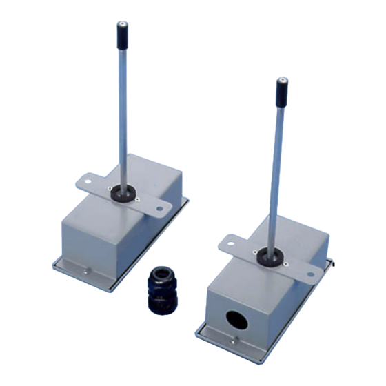
Pressure Transducer
Pressure Transducer
Supply Voltage: 12–40 VDC
Pressure Transducer
Pressure Transducer
PX276 and PX279
PX276 and PX279
12–35 VAC (VDC output units only)
PX276 and PX279
PX276 and PX279
Supply Current: VDC Units – 10 mA max.
mA Units – 20 mA max.
Enclosure: 18 Ga C. R. Steel NEMA 4 (IP-65)
6061T aluminum probe
SPECIFICATIONS
SPECIFICATIONS
SPECIFICATIONS
Finish: Baked on enamel – PMS2GR88B
Accuracy*: ± 1% FS
Accuracy*: ± 1% FS
SPECIFICATIONS
Accuracy*: ± 1% FS
Conformance: EMC Standards EN50082-1(1992)
SPECIFICATIONS
Overpressure: 10 PSID
Overpressure: 10 PSID
Accuracy*: ± 1% FS
Overpressure: 10 PSID
EN55014(1993)/EN60730-1(1992)
Accuracy*: ± 1% FS
Supply Voltage: 12–40 VDC
Supply Voltage: 12–40 VDC
Overpressure: 10 PSID
Supply Voltage: 12–40 VDC
SPECIFICATIONS
SPECIFICATIONS
Compensated Temp Range: 25°F to 150°F (-4°C to 65°C)
Overpressure: 10 PSID
12–35 VAC (VDC output units only)
12–35 VAC (VDC output units only)
Supply Voltage: 12–40 VDC
12–35 VAC (VDC output units only)
Supply Voltage: 12–40 VDC
Accuracy*: ± 1% FS
T. C. Error: ±0.0125%/°F (.02%/°C)
Supply Current: VDC Units – 10 mA max.
Accuracy*: ± 1% FS
Supply Current: VDC Units – 10 mA max.
12–35 VAC (VDC output units only)
Supply Current: VDC Units – 10 mA max.
12–35 VAC (VDC output units only)
Overpressure: 10 PSID
Overpressure: 10 PSID
mA Units – 20 mA max.
Operating Temp Range: 0°F to 175°F (-18°C to 80°C)
mA Units – 20 mA max.
Supply Current: VDC Units – 10 mA max.
mA Units – 20 mA max.
Supply Current: VDC Units – 10 mA max.
Enclosure: 18 Ga C. R. Steel NEMA 4 (IP-65)
Supply Voltage: 12–40 VDC
Supply Voltage: 12–40 VDC
Enclosure: 18 Ga C. R. Steel NEMA 4 (IP-65)
Media Compatibility: Clean dry air or any inert gas
mA Units – 20 mA max.
Enclosure: 18 Ga C. R. Steel NEMA 4 (IP-65)
mA Units – 20 mA max.
6061T aluminum probe
12–35 VAC (VDC output units only)
12–35 VAC (VDC output units only)
6061T aluminum probe
Environmental: 10–90%RH Non-Condensing
Enclosure: 18 Ga C. R. Steel NEMA 4 (IP-65)
6061T aluminum probe
Enclosure: 18 Ga C. R. Steel NEMA 4 (IP-65)
Finish: Baked on enamel – PMS2GR88B
Supply Current: VDC Units – 10 mA max.
Supply Current: VDC Units – 10 mA max.
Finish: Baked on enamel – PMS2GR88B
Termination: Unpluggable screw terminal block
6061T aluminum probe
Finish: Baked on enamel – PMS2GR88B
6061T aluminum probe
Conformance: EMC Standards EN50082-1(1992)
mA Units – 20 mA max.
Conformance: EMC Standards EN50082-1(1992)
mA Units – 20 mA max.
Finish: Baked on enamel – PMS2GR88B
Wire Size: 12 Ga max.
Conformance: EMC Standards EN50082-1(1992)
Finish: Baked on enamel – PMS2GR88B
Enclosure: 18 Ga C. R. Steel NEMA 4 (IP-65)
EN55014(1993)/EN60730-1(1992)
Enclosure: 18 Ga C. R. Steel NEMA 4 (IP-65)
EN55014(1993)/EN60730-1(1992)
Conformance: EMC Standards EN50082-1(1992)
Load Impedance: 3K ohms max. at 40 VDC (mA output units)
EN55014(1993)/EN60730-1(1992)
Conformance: EMC Standards EN50082-1(1992)
Compensated Temp Range: 25°F to 150°F (-4°C to 65°C)
6061T aluminum probe
Compensated Temp Range: 25°F to 150°F (-4°C to 65°C)
6061T aluminum probe
EN55014(1993)/EN60730-1(1992)
Compensated Temp Range: 25°F to 150°F (-4°C to 65°C)
1K ohms min. (VDC output units)
EN55014(1993)/EN60730-1(1992)
T. C. Error: ±0.0125%/°F (.02%/°C)
Finish: Baked on enamel – PMS2GR88B
T. C. Error: ±0.0125%/°F (.02%/°C)
Finish: Baked on enamel – PMS2GR88B
Compensated Temp Range: 25°F to 150°F (-4°C to 65°C)
T. C. Error: ±0.0125%/°F (.02%/°C)
Compensated Temp Range: 25°F to 150°F (-4°C to 65°C)
Weight: Enclosure 1.0 lbs. (.45 kg)
Operating Temp Range: 0°F to 175°F (-18°C to 80°C)
Conformance: EMC Standards EN50082-1(1992)
Operating Temp Range: 0°F to 175°F (-18°C to 80°C)
Conformance: EMC Standards EN50082-1(1992)
T. C. Error: ±0.0125%/°F (.02%/°C)
Operating Temp Range: 0°F to 175°F (-18°C to 80°C)
T. C. Error: ±0.0125%/°F (.02%/°C)
Media Compatibility: Clean dry air or any inert gas
EN55014(1993)/EN60730-1(1992)
Media Compatibility: Clean dry air or any inert gas
*Includes non-linearity, hysteresis and non-repeatability
EN55014(1993)/EN60730-1(1992)
Operating Temp Range: 0°F to 175°F (-18°C to 80°C)
Media Compatibility: Clean dry air or any inert gas
Operating Temp Range: 0°F to 175°F (-18°C to 80°C)
Environmental: 10–90%RH Non-Condensing
Compensated Temp Range: 25°F to 150°F (-4°C to 65°C)
Environmental: 10–90%RH Non-Condensing
Compensated Temp Range: 25°F to 150°F (-4°C to 65°C)
Media Compatibility: Clean dry air or any inert gas
Environmental: 10–90%RH Non-Condensing
Media Compatibility: Clean dry air or any inert gas
Termination: Unpluggable screw terminal block
T. C. Error: ±0.0125%/°F (.02%/°C)
Termination: Unpluggable screw terminal block
Environmental: 10–90%RH Non-Condensing
T. C. Error: ±0.0125%/°F (.02%/°C)
Termination: Unpluggable screw terminal block
Environmental: 10–90%RH Non-Condensing
Wire Size: 12 Ga max.
Operating Temp Range: 0°F to 175°F (-18°C to 80°C)
Wire Size: 12 Ga max.
Termination: Unpluggable screw terminal block
Operating Temp Range: 0°F to 175°F (-18°C to 80°C)
Wire Size: 12 Ga max.
Termination: Unpluggable screw terminal block
Load Impedance: 3K ohms max. at 40 VDC (mA output units)
Media Compatibility: Clean dry air or any inert gas
Load Impedance: 3K ohms max. at 40 VDC (mA output units)
Wire Size: 12 Ga max.
Media Compatibility: Clean dry air or any inert gas
Load Impedance: 3K ohms max. at 40 VDC (mA output units)
Wire Size: 12 Ga max.
1K ohms min. (VDC output units)
Environmental: 10–90%RH Non-Condensing
1K ohms min. (VDC output units)
Load Impedance: 3K ohms max. at 40 VDC (mA output units)
Environmental: 10–90%RH Non-Condensing
1K ohms min. (VDC output units)
Load Impedance: 3K ohms max. at 40 VDC (mA output units)
Weight: Enclosure 1.0 lbs. (.45 kg)
Weight: Enclosure 1.0 lbs. (.45 kg)
Termination: Unpluggable screw terminal block
1K ohms min. (VDC output units)
Weight: Enclosure 1.0 lbs. (.45 kg)
Termination: Unpluggable screw terminal block
1K ohms min. (VDC output units)
Wire Size: 12 Ga max.
*Includes non-linearity, hysteresis and non-repeatability
*Includes non-linearity, hysteresis and non-repeatability
Weight: Enclosure 1.0 lbs. (.45 kg)
Wire Size: 12 Ga max.
*Includes non-linearity, hysteresis and non-repeatability
Weight: Enclosure 1.0 lbs. (.45 kg)
Load Impedance: 3K ohms max. at 40 VDC (mA output units)
*Includes non-linearity, hysteresis and non-repeatability
Load Impedance: 3K ohms max. at 40 VDC (mA output units)
*Includes non-linearity, hysteresis and non-repeatability
1K ohms min. (VDC output units)
1K ohms min. (VDC output units)
Weight: Enclosure 1.0 lbs. (.45 kg)
Weight: Enclosure 1.0 lbs. (.45 kg)
*Includes non-linearity, hysteresis and non-repeatability
*Includes non-linearity, hysteresis and non-repeatability
INSTALLATION
Inspection
Inspect the package for damage. If damaged, notify the appropriate carrier
immediately. If undamaged, open the package and inspect the device for
obvious damage. Return damaged products.
Requirements
•
Tools (not provided)
- Digital Volt-ohm Meter (DVM)
INSTALLATION
INSTALLATION
- Appropriate screwdriver for mounting screws
INSTALLATION
- Appropriate drill and drill bit for mounting screws
INSTALLATION
Inspection
Inspect the package for damage. If damaged, notify the appropriate carrier
Inspection
Inspect the package for damage. If damaged, notify the appropriate carrier
INSTALLATION
•
Appropriate accessories
Inspection
immediately. If undamaged, open the package and inspect the device for
Inspect the package for damage. If damaged, notify the appropriate carrier
immediately. If undamaged, open the package and inspect the device for
•
Two #8 self-tapping mounting screws (not provided)
immediately. If undamaged, open the package and inspect the device for
obvious damage. Return damaged products.
obvious damage. Return damaged products.
Inspection
Inspect the package for damage. If damaged, notify the appropriate carrier
Inspection
obvious damage. Return damaged products.
Inspect the package for damage. If damaged, notify the appropriate carrier
immediately. If undamaged, open the package and inspect the device for
•
Training: Installer must be a qualified, experienced technician
Requirements
•
Tools (not provided)
immediately. If undamaged, open the package and inspect the device for
Requirements
•
Tools (not provided)
INSTALLATION
obvious damage. Return damaged products.
- Digital Volt-ohm Meter (DVM)
Requirements
•
Tools (not provided)
obvious damage. Return damaged products.
- Digital Volt-ohm Meter (DVM)
Warning:
- Appropriate screwdriver for mounting screws
- Digital Volt-ohm Meter (DVM)
- Appropriate screwdriver for mounting screws
•
Tools (not provided)
Requirements
INSTALLATION
Inspection
- Appropriate drill and drill bit for mounting screws
- Appropriate screwdriver for mounting screws
Requirements
•
Tools (not provided)
Inspect the package for damage. If damaged, notify the appropriate carrier
•
Do not use on oxygen service, in an explosive/hazardous environment, or
- Appropriate drill and drill bit for mounting screws
- Digital Volt-ohm Meter (DVM)
- Appropriate drill and drill bit for mounting screws
- Digital Volt-ohm Meter (DVM)
immediately. If undamaged, open the package and inspect the device for
•
Appropriate accessories
with flammable/combustible media.
•
Appropriate accessories
- Appropriate screwdriver for mounting screws
- Appropriate screwdriver for mounting screws
obvious damage. Return damaged products.
•
Appropriate accessories
Inspection
•
Inspect the package for damage. If damaged, notify the appropriate carrier
Two #8 self-tapping mounting screws (not provided)
- Appropriate drill and drill bit for mounting screws
•
Two #8 self-tapping mounting screws (not provided)
•
Disconnect power supply before installation to prevent electrical shock
- Appropriate drill and drill bit for mounting screws
•
immediately. If undamaged, open the package and inspect the device for
Two #8 self-tapping mounting screws (not provided)
•
Appropriate accessories
and equipment damage.
•
Training: Installer must be a qualified, experienced technician
Requirements
•
Tools (not provided)
•
Training: Installer must be a qualified, experienced technician
•
Appropriate accessories
obvious damage. Return damaged products.
•
Two #8 self-tapping mounting screws (not provided)
•
Training: Installer must be a qualified, experienced technician
- Digital Volt-ohm Meter (DVM)
•
Make all connections in accordance with the job wiring diagram and in
•
Two #8 self-tapping mounting screws (not provided)
Warning:
- Appropriate screwdriver for mounting screws
Warning:
accordance with national and local electrical codes. Use copper
•
Training: Installer must be a qualified, experienced technician
Requirements
•
Tools (not provided)
•
Warning:
Training: Installer must be a qualified, experienced technician
- Appropriate drill and drill bit for mounting screws
•
Do not use on oxygen service, in an explosive/hazardous environment, or
conductors only.
•
Do not use on oxygen service, in an explosive/hazardous environment, or
- Digital Volt-ohm Meter (DVM)
•
with flammable/combustible media.
Do not use on oxygen service, in an explosive/hazardous environment, or
•
Appropriate accessories
Warning:
with flammable/combustible media.
- Appropriate screwdriver for mounting screws
Warning:
with flammable/combustible media.
•
Disconnect power supply before installation to prevent electrical shock
•
Two #8 self-tapping mounting screws (not provided)
•
•
Do not use on oxygen service, in an explosive/hazardous environment, or
Disconnect power supply before installation to prevent electrical shock
- Appropriate drill and drill bit for mounting screws
•
Do not use on oxygen service, in an explosive/hazardous environment, or
Caution:
and equipment damage.
•
Disconnect power supply before installation to prevent electrical shock
with flammable/combustible media.
and equipment damage.
•
Appropriate accessories
•
Training: Installer must be a qualified, experienced technician
with flammable/combustible media.
and equipment damage.
•
Make all connections in accordance with the job wiring diagram and in
•
Use electrostatic discharge precautions (e.g., use of wrist straps) during
•
•
Disconnect power supply before installation to prevent electrical shock
Make all connections in accordance with the job wiring diagram and in
•
Two #8 self-tapping mounting screws (not provided)
•
Disconnect power supply before installation to prevent electrical shock
•
Make all connections in accordance with the job wiring diagram and in
accordance with national and local electrical codes. Use copper
and equipment damage.
accordance with national and local electrical codes. Use copper
installation and wiring to prevent equipment damage.
Warning:
and equipment damage.
conductors only.
accordance with national and local electrical codes. Use copper
•
conductors only.
Training: Installer must be a qualified, experienced technician
•
Make all connections in accordance with the job wiring diagram and in
•
Avoid locations where severe shock or vibration, excessive moisture or
•
Do not use on oxygen service, in an explosive/hazardous environment, or
conductors only.
•
Make all connections in accordance with the job wiring diagram and in
accordance with national and local electrical codes. Use copper
with flammable/combustible media.
corrosive fumes are present. NEMA Type 4 housings are intended for
accordance with national and local electrical codes. Use copper
Warning:
conductors only.
Caution:
outdoor use primarily to provide a degree of protection against wind-blown
Caution:
•
Disconnect power supply before installation to prevent electrical shock
conductors only.
•
Do not use on oxygen service, in an explosive/hazardous environment, or
Caution:
•
Use electrostatic discharge precautions (e.g., use of wrist straps) during
dust, rain, and hose-directed water.
and equipment damage.
•
Use electrostatic discharge precautions (e.g., use of wrist straps) during
with flammable/combustible media.
installation and wiring to prevent equipment damage.
•
Use electrostatic discharge precautions (e.g., use of wrist straps) during
Caution:
•
installation and wiring to prevent equipment damage.
Make all connections in accordance with the job wiring diagram and in
•
Do not exceed ratings of the device.
Caution:
•
installation and wiring to prevent equipment damage.
Disconnect power supply before installation to prevent electrical shock
•
Avoid locations where severe shock or vibration, excessive moisture or
accordance with national and local electrical codes. Use copper
•
•
Use electrostatic discharge precautions (e.g., use of wrist straps) during
Avoid locations where severe shock or vibration, excessive moisture or
•
Use electrostatic discharge precautions (e.g., use of wrist straps) during
and equipment damage.
•
Avoid locations where severe shock or vibration, excessive moisture or
corrosive fumes are present. NEMA Type 4 housings are intended for
conductors only.
corrosive fumes are present. NEMA Type 4 housings are intended for
installation and wiring to prevent equipment damage.
installation and wiring to prevent equipment damage.
Refer to Figure 7 for mounting dimensions.
outdoor use primarily to provide a degree of protection against wind-blown
Mounting
corrosive fumes are present. NEMA Type 4 housings are intended for
•
Make all connections in accordance with the job wiring diagram and in
outdoor use primarily to provide a degree of protection against wind-blown
•
Avoid locations where severe shock or vibration, excessive moisture or
dust, rain, and hose-directed water.
outdoor use primarily to provide a degree of protection against wind-blown
•
Avoid locations where severe shock or vibration, excessive moisture or
accordance with national and local electrical codes. Use copper
dust, rain, and hose-directed water.
1. Remove the transducer cover using a Phillips head screwdriver.
corrosive fumes are present. NEMA Type 4 housings are intended for
Caution:
dust, rain, and hose-directed water.
corrosive fumes are present. NEMA Type 4 housings are intended for
•
Do not exceed ratings of the device.
conductors only.
•
outdoor use primarily to provide a degree of protection against wind-blown
Do not exceed ratings of the device.
2. Select the mounting location.
outdoor use primarily to provide a degree of protection against wind-blown
•
Use electrostatic discharge precautions (e.g., use of wrist straps) during
•
Do not exceed ratings of the device.
dust, rain, and hose-directed water.
dust, rain, and hose-directed water.
3. Mount transducer on a vertical surface with two #8 self-tapping screws
installation and wiring to prevent equipment damage.
•
Do not exceed ratings of the device.
Refer to Figure 7 for mounting dimensions.
Mounting
Refer to Figure 7 for mounting dimensions.
Mounting
Caution:
(not provided).
•
•
Do not exceed ratings of the device.
Avoid locations where severe shock or vibration, excessive moisture or
Refer to Figure 7 for mounting dimensions.
Mounting
1. Remove the transducer cover using a Phillips head screwdriver.
1. Remove the transducer cover using a Phillips head screwdriver.
•
corrosive fumes are present. NEMA Type 4 housings are intended for
Use electrostatic discharge precautions (e.g., use of wrist straps) during
4. Pull wires through bottom of enclosure and make necessary connections.
1. Remove the transducer cover using a Phillips head screwdriver.
Refer to Figure 7 for mounting dimensions.
2. Select the mounting location.
Mounting
outdoor use primarily to provide a degree of protection against wind-blown
installation and wiring to prevent equipment damage.
2. Select the mounting location.
Refer to Figure 7 for mounting dimensions.
Mounting
5. Replace cover and make pneumatic connections.
2. Select the mounting location.
dust, rain, and hose-directed water.
1. Remove the transducer cover using a Phillips head screwdriver.
3. Mount transducer on a vertical surface with two #8 self-tapping screws
3. Mount transducer on a vertical surface with two #8 self-tapping screws
•
Avoid locations where severe shock or vibration, excessive moisture or
1. Remove the transducer cover using a Phillips head screwdriver.
(not provided).
3. Mount transducer on a vertical surface with two #8 self-tapping screws
•
Do not exceed ratings of the device.
2. Select the mounting location.
(not provided).
corrosive fumes are present. NEMA Type 4 housings are intended for
2. Select the mounting location.
(not provided).
Wiring
4. Pull wires through bottom of enclosure and make necessary connections.
Use maximum 12 AWG wire for wiring terminals. Refer to Figures 1, 2, 3, & 4
outdoor use primarily to provide a degree of protection against wind-blown
4. Pull wires through bottom of enclosure and make necessary connections.
3. Mount transducer on a vertical surface with two #8 self-tapping screws
3. Mount transducer on a vertical surface with two #8 self-tapping screws
4. Pull wires through bottom of enclosure and make necessary connections.
for wiring information and Figures 5 & 6 for switch designations.
dust, rain, and hose-directed water.
5. Replace cover and make pneumatic connections.
(not provided).
Refer to Figure 7 for mounting dimensions.
5. Replace cover and make pneumatic connections.
Mounting
(not provided).
5. Replace cover and make pneumatic connections.
4. Pull wires through bottom of enclosure and make necessary connections.
•
Do not exceed ratings of the device.
1. Remove the transducer cover using a Phillips head screwdriver.
4. Pull wires through bottom of enclosure and make necessary connections.
Wiring
5. Replace cover and make pneumatic connections.
Use maximum 12 AWG wire for wiring terminals. Refer to Figures 1, 2, 3, & 4
Wiring
2. Select the mounting location.
Use maximum 12 AWG wire for wiring terminals. Refer to Figures 1, 2, 3, & 4
5. Replace cover and make pneumatic connections.
Wiring
for wiring information and Figures 5 & 6 for switch designations.
Use maximum 12 AWG wire for wiring terminals. Refer to Figures 1, 2, 3, & 4
for wiring information and Figures 5 & 6 for switch designations.
Refer to Figure 7 for mounting dimensions.
Mounting
3. Mount transducer on a vertical surface with two #8 self-tapping screws
for wiring information and Figures 5 & 6 for switch designations.
Wiring
(not provided).
Use maximum 12 AWG wire for wiring terminals. Refer to Figures 1, 2, 3, & 4
1. Remove the transducer cover using a Phillips head screwdriver.
Wiring
Use maximum 12 AWG wire for wiring terminals. Refer to Figures 1, 2, 3, & 4
for wiring information and Figures 5 & 6 for switch designations.
4. Pull wires through bottom of enclosure and make necessary connections.
®
Pressure Transducer
Pressure Transducer
PX276 and PX279
PX276 and PX279
M3505/0816
Wiring PX276 Units with mA Output
PX276 Duct Pressure Transducer with mA Output
Zu
3 YEAR
S
Wiring PX276 Units with mA Output
Wiring PX276 Units with mA Output
Wiring PX276 Units with mA Output
PX276 pressure transducers with 4–20 mA output units are powered with a 12–40 VDC supply.
PX276 Duct Pressure Transducer with mA Output
PX276 Duct Pressure Transducer with mA Output
Wiring PX276 Units with mA Output
PX276 Duct Pressure Transducer with mA Output
Wiring PX276 Units with mA Output
The following describes the proper wiring of these pressure transducers with mA output:
PX276 Duct Pressure Transducer with mA Output
PX276 Duct Pressure Transducer with mA Output
1. Remove the terminal block by carefully pulling it off the circuit board.
Wiring PX276 Units with mA Output
Wiring PX276 Units with mA Output
2. Locate the [+] and [-] terminal markings on the board.
PX276 Duct Pressure Transducer with mA Output
3. Attach the supply voltage to the [+] lead.
PX276 Duct Pressure Transducer with mA Output
4. Connect the 4–20 mA output ([-] terminal) to the controller's input terminal.
Zu
Zu
5. Ensure that the power supply common is attached to the common bus of the controller.
Zu
S
S
6. Re-insert the terminal block to the circuit board and apply power to the unit.
Zu
S
Zu
7. Check for the appropriate output signal using a DVM set on DC milliamps connected in
S
series with the [-] terminal.
S
PX276 pressure transducers with 4–20 mA output units are powered with a 12–40 VDC supply.
PX276 pressure transducers with 4–20 mA output units are powered with a 12–40 VDC supply.
Zu
Zu
PX276 pressure transducers with 4–20 mA output units are powered with a 12–40 VDC supply.
The following describes the proper wiring of these pressure transducers with mA output:
Wiring PX279 Units with VDC Output
The following describes the proper wiring of these pressure transducers with mA output:
PX276 pressure transducers with 4–20 mA output units are powered with a 12–40 VDC supply.
S
The following describes the proper wiring of these pressure transducers with mA output:
S
PX276 pressure transducers with 4–20 mA output units are powered with a 12–40 VDC supply.
1. Remove the terminal block by carefully pulling it off the circuit board.
1. Remove the terminal block by carefully pulling it off the circuit board.
The following describes the proper wiring of these pressure transducers with mA output:
1. Remove the terminal block by carefully pulling it off the circuit board.
2. Locate the [+] and [-] terminal markings on the board.
PX279 Duct Pressure Transducer with VDC Output
The following describes the proper wiring of these pressure transducers with mA output:
2. Locate the [+] and [-] terminal markings on the board.
2. Locate the [+] and [-] terminal markings on the board.
1. Remove the terminal block by carefully pulling it off the circuit board.
3. Attach the supply voltage to the [+] lead.
3. Attach the supply voltage to the [+] lead.
1. Remove the terminal block by carefully pulling it off the circuit board.
PX276 pressure transducers with 4–20 mA output units are powered with a 12–40 VDC supply.
3. Attach the supply voltage to the [+] lead.
PX276 pressure transducers with 4–20 mA output units are powered with a 12–40 VDC supply.
4. Connect the 4–20 mA output ([-] terminal) to the controller's input terminal.
2. Locate the [+] and [-] terminal markings on the board.
4. Connect the 4–20 mA output ([-] terminal) to the controller's input terminal.
2. Locate the [+] and [-] terminal markings on the board.
4. Connect the 4–20 mA output ([-] terminal) to the controller's input terminal.
3. Attach the supply voltage to the [+] lead.
The following describes the proper wiring of these pressure transducers with mA output:
5. Ensure that the power supply common is attached to the common bus of the controller.
5. Ensure that the power supply common is attached to the common bus of the controller.
The following describes the proper wiring of these pressure transducers with mA output:
3. Attach the supply voltage to the [+] lead.
5. Ensure that the power supply common is attached to the common bus of the controller.
6. Re-insert the terminal block to the circuit board and apply power to the unit.
4. Connect the 4–20 mA output ([-] terminal) to the controller's input terminal.
6. Re-insert the terminal block to the circuit board and apply power to the unit.
1. Remove the terminal block by carefully pulling it off the circuit board.
4. Connect the 4–20 mA output ([-] terminal) to the controller's input terminal.
1. Remove the terminal block by carefully pulling it off the circuit board.
6. Re-insert the terminal block to the circuit board and apply power to the unit.
5. Ensure that the power supply common is attached to the common bus of the controller.
7. Check for the appropriate output signal using a DVM set on DC milliamps connected in
7. Check for the appropriate output signal using a DVM set on DC milliamps connected in
2. Locate the [+] and [-] terminal markings on the board.
5. Ensure that the power supply common is attached to the common bus of the controller.
2. Locate the [+] and [-] terminal markings on the board.
7. Check for the appropriate output signal using a DVM set on DC milliamps connected in
series with the [-] terminal.
6. Re-insert the terminal block to the circuit board and apply power to the unit.
series with the [-] terminal.
3. Attach the supply voltage to the [+] lead.
6. Re-insert the terminal block to the circuit board and apply power to the unit.
series with the [-] terminal.
3. Attach the supply voltage to the [+] lead.
7. Check for the appropriate output signal using a DVM set on DC milliamps connected in
4. Connect the 4–20 mA output ([-] terminal) to the controller's input terminal.
7. Check for the appropriate output signal using a DVM set on DC milliamps connected in
Zu
Wiring PX279 Units with VDC Output
series with the [-] terminal.
4. Connect the 4–20 mA output ([-] terminal) to the controller's input terminal.
Wiring PX279 Units with VDC Output
series with the [-] terminal.
5. Ensure that the power supply common is attached to the common bus of the controller.
Wiring PX279 Units with VDC Output
5. Ensure that the power supply common is attached to the common bus of the controller.
6. Re-insert the terminal block to the circuit board and apply power to the unit.
S
Wiring PX279 Units with VDC Output
PX279 Duct Pressure Transducer with VDC Output
6. Re-insert the terminal block to the circuit board and apply power to the unit.
PX279 Duct Pressure Transducer with VDC Output
Wiring PX279 Units with VDC Output
7. Check for the appropriate output signal using a DVM set on DC milliamps connected in
PX279 Duct Pressure Transducer with VDC Output
7. Check for the appropriate output signal using a DVM set on DC milliamps connected in
series with the [-] terminal.
series with the [-] terminal.
PX279 Duct Pressure Transducer with VDC Output
PX279 Duct Pressure Transducer with VDC Output
PX279 pressure transducers with VDC output are field selectable 0–5 VDC or 0–10 VDC
Wiring PX279 Units with VDC Output
output and can be powered with either 12–40 VDC or 12–35 VAC.
Wiring PX279 Units with VDC Output
The following describes the proper wiring of these pressure transducers with VDC output:
PX279 Duct Pressure Transducer with VDC Output
PX279 Duct Pressure Transducer with VDC Output
Zu
Zu
1. Remove the terminal block by carefully pulling it off the circuit board.
Zu
2. Locate the [+], [-] and [0] terminal markings on the board.
S
S
Zu
S
Zu
3. Attach the power wires to the [+] and [-] terminals. The [-] terminal is also the
negative output terminal.
S
S
4. Connect the [0] terminal, which is the positive VDC output terminal, to the controller's input
PX279 pressure transducers with VDC output are field selectable 0–5 VDC or 0–10 VDC
PX279 pressure transducers with VDC output are field selectable 0–5 VDC or 0–10 VDC
PX279 pressure transducers with VDC output are field selectable 0–5 VDC or 0–10 VDC
output and can be powered with either 12–40 VDC or 12–35 VAC.
terminal.
Zu
output and can be powered with either 12–40 VDC or 12–35 VAC.
output and can be powered with either 12–40 VDC or 12–35 VAC.
5. Re-insert the terminal block to the circuit board and apply power to the unit.
Zu
PX279 pressure transducers with VDC output are field selectable 0–5 VDC or 0–10 VDC
The following describes the proper wiring of these pressure transducers with VDC output:
PX279 pressure transducers with VDC output are field selectable 0–5 VDC or 0–10 VDC
S
The following describes the proper wiring of these pressure transducers with VDC output:
output and can be powered with either 12–40 VDC or 12–35 VAC.
6. Check the appropriate VDC output using a voltmeter set on DC volts across the [0] and [-]
The following describes the proper wiring of these pressure transducers with VDC output:
output and can be powered with either 12–40 VDC or 12–35 VAC.
S
1. Remove the terminal block by carefully pulling it off the circuit board.
terminals.
1. Remove the terminal block by carefully pulling it off the circuit board.
The following describes the proper wiring of these pressure transducers with VDC output:
1. Remove the terminal block by carefully pulling it off the circuit board.
2. Locate the [+], [-] and [0] terminal markings on the board.
The following describes the proper wiring of these pressure transducers with VDC output:
2. Locate the [+], [-] and [0] terminal markings on the board.
PX279 pressure transducers with VDC output are field selectable 0–5 VDC or 0–10 VDC
2. Locate the [+], [-] and [0] terminal markings on the board.
1. Remove the terminal block by carefully pulling it off the circuit board.
3. Attach the power wires to the [+] and [-] terminals. The [-] terminal is also the
3. Attach the power wires to the [+] and [-] terminals. The [-] terminal is also the
1. Remove the terminal block by carefully pulling it off the circuit board.
output and can be powered with either 12–40 VDC or 12–35 VAC.
3. Attach the power wires to the [+] and [-] terminals. The [-] terminal is also the
negative output terminal.
TYPICAL APPLICATIONS (wiring diagrams)
2. Locate the [+], [-] and [0] terminal markings on the board.
PX279 pressure transducers with VDC output are field selectable 0–5 VDC or 0–10 VDC
negative output terminal.
2. Locate the [+], [-] and [0] terminal markings on the board.
negative output terminal.
4. Connect the [0] terminal, which is the positive VDC output terminal, to the controller's input
output and can be powered with either 12–40 VDC or 12–35 VAC.
3. Attach the power wires to the [+] and [-] terminals. The [-] terminal is also the
4. Connect the [0] terminal, which is the positive VDC output terminal, to the controller's input
The following describes the proper wiring of these pressure transducers with VDC output:
3. Attach the power wires to the [+] and [-] terminals. The [-] terminal is also the
4. Connect the [0] terminal, which is the positive VDC output terminal, to the controller's input
terminal.
negative output terminal.
Figure 1 and Figure 2 illustrate typical wiring diagrams for the PX276 Series, 4–20 mA,
terminal.
negative output terminal.
The following describes the proper wiring of these pressure transducers with VDC output:
terminal.
5. Re-insert the terminal block to the circuit board and apply power to the unit.
1. Remove the terminal block by carefully pulling it off the circuit board.
4. Connect the [0] terminal, which is the positive VDC output terminal, to the controller's input
5. Re-insert the terminal block to the circuit board and apply power to the unit.
two-wire output duct pressure transducers.
4. Connect the [0] terminal, which is the positive VDC output terminal, to the controller's input
5. Re-insert the terminal block to the circuit board and apply power to the unit.
6. Check the appropriate VDC output using a voltmeter set on DC volts across the [0] and [-]
2. Locate the [+], [-] and [0] terminal markings on the board.
terminal.
6. Check the appropriate VDC output using a voltmeter set on DC volts across the [0] and [-]
1. Remove the terminal block by carefully pulling it off the circuit board.
terminal.
6. Check the appropriate VDC output using a voltmeter set on DC volts across the [0] and [-]
terminals.
5. Re-insert the terminal block to the circuit board and apply power to the unit.
3. Attach the power wires to the [+] and [-] terminals. The [-] terminal is also the
terminals.
Figure 1 – Wiring for mA Output Duct Pressure Transducers with External DC
2. Locate the [+], [-] and [0] terminal markings on the board.
5. Re-insert the terminal block to the circuit board and apply power to the unit.
terminals.
negative output terminal.
6. Check the appropriate VDC output using a voltmeter set on DC volts across the [0] and [-]
Power Supply
6. Check the appropriate VDC output using a voltmeter set on DC volts across the [0] and [-]
3. Attach the power wires to the [+] and [-] terminals. The [-] terminal is also the
4. Connect the [0] terminal, which is the positive VDC output terminal, to the controller's input
terminals.
terminals.
negative output terminal.
TYPICAL APPLICATIONS (wiring diagrams)
TYPICAL APPLICATIONS (wiring diagrams)
terminal.
mA Output Transducer Only
TYPICAL APPLICATIONS (wiring diagrams)
4. Connect the [0] terminal, which is the positive VDC output terminal, to the controller's input
5. Re-insert the terminal block to the circuit board and apply power to the unit.
Figure 1 and Figure 2 illustrate typical wiring diagrams for the PX276 Series, 4–20 mA,
+
terminal.
Figure 1 and Figure 2 illustrate typical wiring diagrams for the PX276 Series, 4–20 mA,
TYPICAL APPLICATIONS (wiring diagrams)
6. Check the appropriate VDC output using a voltmeter set on DC volts across the [0] and [-]
TYPICAL APPLICATIONS (wiring diagrams)
Figure 1 and Figure 2 illustrate typical wiring diagrams for the PX276 Series, 4–20 mA,
two-wire output duct pressure transducers.
two-wire output duct pressure transducers.
5. Re-insert the terminal block to the circuit board and apply power to the unit.
terminals.
two-wire output duct pressure transducers.
Figure 1 and Figure 2 illustrate typical wiring diagrams for the PX276 Series, 4–20 mA,
6. Check the appropriate VDC output using a voltmeter set on DC volts across the [0] and [-]
Figure 1 and Figure 2 illustrate typical wiring diagrams for the PX276 Series, 4–20 mA,
Figure 1 – Wiring for mA Output Duct Pressure Transducers with External DC
Figure 1 – Wiring for mA Output Duct Pressure Transducers with External DC
two-wire output duct pressure transducers.
terminals.
two-wire output duct pressure transducers.
Figure 1 – Wiring for mA Output Duct Pressure Transducers with External DC
Power Supply
Power Supply
TYPICAL APPLICATIONS (wiring diagrams)
Power Supply
Figure 1 – Wiring for mA Output Duct Pressure Transducers with External DC
Figure 1 – Wiring for mA Output Duct Pressure Transducers with External DC
mA Output Transducer Only
mA Output Transducer Only
Power Supply
Figure 1 and Figure 2 illustrate typical wiring diagrams for the PX276 Series, 4–20 mA,
TYPICAL APPLICATIONS (wiring diagrams)
Power Supply
mA Output Transducer Only
+
+
two-wire output duct pressure transducers.
+
mA Output Transducer Only
Figure 1 and Figure 2 illustrate typical wiring diagrams for the PX276 Series, 4–20 mA,
mA Output Transducer Only
+
Figure 1 – Wiring for mA Output Duct Pressure Transducers with External DC
two-wire output duct pressure transducers.
+
Figure 2 – Wiring for mA Output Duct Pressure Transducers where the Controller or
Power Supply
Meter has an Internal DC Power Supply
Figure 1 – Wiring for mA Output Duct Pressure Transducers with External DC
mA Output Transducer Only
Power Supply
+
mA Output Transducer Only
mA Output Transducer Only
+
+
Figure 2 – Wiring for mA Output Duct Pressure Transducers where the Controller or
Figure 2 – Wiring for mA Output Duct Pressure Transducers where the Controller or
Figure 2 – Wiring for mA Output Duct Pressure Transducers where the Controller or
Meter has an Internal DC Power Supply
Meter has an Internal DC Power Supply
Meter has an Internal DC Power Supply
Figure 2 – Wiring for mA Output Duct Pressure Transducers where the Controller or
Figure 2 – Wiring for mA Output Duct Pressure Transducers where the Controller or
mA Output Transducer Only
Meter has an Internal DC Power Supply
mA Output Transducer Only
Meter has an Internal DC Power Supply
mA Output Transducer Only
+
+
Figure 3 and Figure 4 illustrate typical wiring diagrams for the PX279, 0–5/0–10 VDC
+
mA Output Transducer Only
output duct pressure transducer.
mA Output Transducer Only
+
Figure 2 – Wiring for mA Output Duct Pressure Transducers where the Controller or
+
Meter has an Internal DC Power Supply
Figure 3 – Wiring for VDC Output Duct Pressure Transducers when applied with
External AC Supply.
Figure 2 – Wiring for mA Output Duct Pressure Transducers where the Controller or
Figure 3 and Figure 4 illustrate typical wiring diagrams for the PX279, 0–5/0–10 VDC
Figure 3 and Figure 4 illustrate typical wiring diagrams for the PX279, 0–5/0–10 VDC
mA Output Transducer Only
output duct pressure transducer.
Figure 3 and Figure 4 illustrate typical wiring diagrams for the PX279, 0–5/0–10 VDC
Meter has an Internal DC Power Supply
output duct pressure transducer.
+
VDC Output Transducer Only
output duct pressure transducer.
Figure 3 and Figure 4 illustrate typical wiring diagrams for the PX279, 0–5/0–10 VDC
Figure 3 and Figure 4 illustrate typical wiring diagrams for the PX279, 0–5/0–10 VDC
Figure 3 – Wiring for VDC Output Duct Pressure Transducers when applied with
+
Figure 3 – Wiring for VDC Output Duct Pressure Transducers when applied with
Supply
output duct pressure transducer.
mA Output Transducer Only
Figure 3 – Wiring for VDC Output Duct Pressure Transducers when applied with
External AC Supply.
output duct pressure transducer.
External AC Supply.
Common
+
External AC Supply.
Figure 3 – Wiring for VDC Output Duct Pressure Transducers when applied with
O
Signal
Figure 3 – Wiring for VDC Output Duct Pressure Transducers when applied with
VDC Output Transducer Only
External AC Supply.
VDC Output Transducer Only
External AC Supply.
Figure 3 and Figure 4 illustrate typical wiring diagrams for the PX279, 0–5/0–10 VDC
VDC Output Transducer Only
+
Supply
+
Supply
output duct pressure transducer.
+
Supply
VDC Output Transducer Only
Common
Common
VDC Output Transducer Only
Common
O
+
Signal
Supply
O
Figure 3 – Wiring for VDC Output Duct Pressure Transducers when applied with
Signal
+
Figure 3 and Figure 4 illustrate typical wiring diagrams for the PX279, 0–5/0–10 VDC
Supply
Signal
O
Common
External AC Supply.
output duct pressure transducer.
Common
Signal
O
O
Signal
VDC Output Transducer Only
Figure 3 – Wiring for VDC Output Duct Pressure Transducers when applied with
+
External AC Supply.
Supply
Common
O
VDC Output Transducer Only
Signal
12–40 VDC Power Supply
+
Controller / Meter / Recorder
+
Input Signal
Common
12–40 VDC Power Supply
12–40 VDC Power Supply
12–40 VDC Power Supply
+
Shield/Ground
+
+
12–40 VDC Power Supply
12–40 VDC Power Supply
+
+
Controller / Meter / Recorder
Controller / Meter / Recorder
Controller / Meter / Recorder
+
+
Input Signal
Input Signal
+
Controller / Meter / Recorder
Input Signal
Common
12–40 VDC Power Supply
Common
Controller / Meter / Recorder
+
Common
Shield/Ground
Input Signal
+
Shield/Ground
+
Controller / Meter / Recorder
Input Signal
Shield/Ground
Common
12–40 VDC Power Supply
Common
+
Input Signal
Shield/Ground
+
Shield/Ground
Controller / Meter / Recorder
Common
+
Shield/Ground
Input Signal
Common
Controller / Meter / Recorder
Controller / Meter / Recorder
Controller / Meter / Recorder
Shield/Ground
+
Input Signal
Controller / Meter / Recorder
+
+
Input Signal
Input Signal
Common
+
Controller / Meter / Recorder
Input Signal
Common
Common
Controller / Meter / Recorder
Shield/Ground
+
Common
Shield/Ground
Shield/Ground
Input Signal
+
Input Signal
Shield/Ground
Common
Common
Shield/Ground
Shield/Ground
Controller / Meter / Recorder
+
Input Signal
12–35 VAC Transformer
Common
+
Hot
Controller / Meter / Recorder
Shield/Ground
Neutral
+
Input Signal
Common
12–35 VAC Transformer
12–35 VAC Transformer
Controller / Meter / Recorder
Shield/Ground
12–35 VAC Transformer
+
Hot
+
+
Hot
Input Signal
+
Hot
12–35 VAC Transformer
Neutral
Neutral
12–35 VAC Transformer
Common
Neutral
+
Hot
+
Controller / Meter / Recorder
Hot
Shield/Ground
Controller / Meter / Recorder
Neutral
Controller / Meter / Recorder
+
Neutral
+
Input Signal
Input Signal
+
Input Signal
Controller / Meter / Recorder
Common
Common
12–35 VAC Transformer
Controller / Meter / Recorder
Common
+
Shield/Ground
Input Signal
Shield/Ground
+
+
Hot
Input Signal
Shield/Ground
Common
Neutral
Common
Shield/Ground
12–35 VAC Transformer
Shield/Ground
Advertisement

Related Manuals for Omega PX276


Summary of Contents for Omega PX276
- Page 1 Enclosure: 18 Ga C. R. Steel NEMA 4 (IP-65) Wiring PX276 Units with mA Output PX276 pressure transducers with 4–20 mA output units are powered with a 12–40 VDC supply. PX276 Duct Pressure Transducer with mA Output PX276 Duct Pressure Transducer with mA Output...
- Page 2 CONDITIONS: Equipment sold by OMEGA is not intended to be used, nor shall it be used: (1) as a “Basic Component” under 10 CFR 21 (NRC), used in or with any nuclear installation or activity; or (2) in medical applications or used on humans. Should any Product(s) be used in or with any nuclear installation or activity, medical application, used on humans, or misused in any way, OMEGA assumes no responsibility as set forth in our basic WARRANTY/DISCLAIMER language, and, additionally, purchaser will indemnify OMEGA and hold OMEGA harmless from any liability or damage whatsoever arising out of the use of the Product(s) in such a manner.