
Related Manuals for Honda HSM1336i


Summary of Contents for Honda HSM1336i
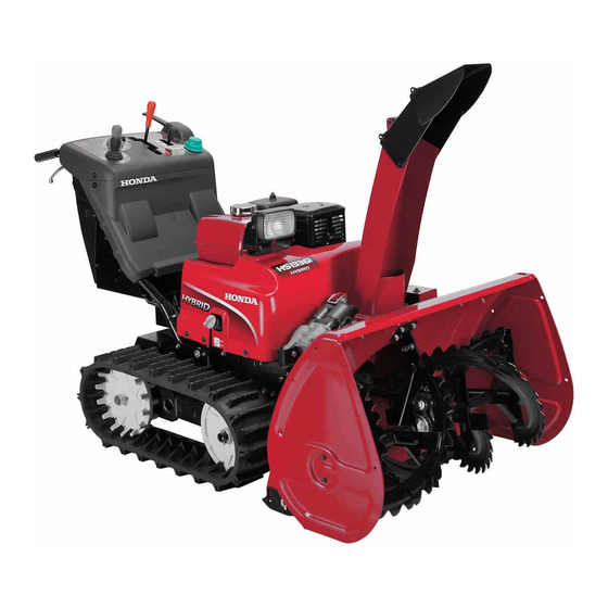
- Page 1 Owner , s Manual SNOWBLOWER HSM1336i Includes US and Canadian Models 2018 Honda Motor Co., Ltd. -All Rights Reserved...
- Page 2 The information and specifications included in this publication were in effect at the time of approval for printing. Honda Motor Co., Ltd. reserves the right, however, to discontinue or change specifications or design at any time without notice and without incurring any obligation whatsoever.
- Page 3 INTRODUCTION Congratulations on your selection of a Honda snow blower. We are certain you will be pleased with your purchase of one of the finest snow blowers on the market. We want to help you get the best results from your new snow blower and to operate it safely.
- Page 4 INTRODUCTION A FEW WORDS ABOUT SAFETY Your safety and the safety of others are very important. And using this snow blower safely is an important responsibility. To help you make informed decisions about safety, we have provided operating procedures and other information on labels and in this manual.
-
Page 5: Table Of Contents
CONTENTS SNOW BLOWER SAFETY ................6 IMPORTANT SAFETY INFORMATION ..........6 SAFETY LABEL LOCATIONS ..............9 CONTROLS & FEATURES ..............14 COMPONENT & CONTROL LOCATIONS ..........14 CONTROLS ..................17 Engine Switch .................17 Fuel Valve Lever ................18 Manual Start Lever .................18 Mode Selector Switch ..............19 Throttle Control Lever ..............21 Main Shift Lever ................24 Drive Clutch Lever ................25 Auger Clutch Switch ...............25... - Page 6 CONTENTS OPERATION ....................43 SNOWBLOWING PRECAUTIONS ............43 STARTING THE ENGINE ..............44 OPERATING THE CONTROLS FOR CLEARING SNOW ....47 Skid and Scraper ................47 Auger Housing Height ..............50 Auger Housing Tilt Angle (USA model only) .......52 Operation ..................53 Turning the Snow Blower ..............63 Battery run mode ................66 CLEARING SNOW ................68 REMOVING OBSTRUCTIONS ............71...
- Page 7 Serial Number Locations ..............131 Carburetor Modification for High Altitude Operation ....132 Emission Control System Information ..........133 Air Index ....................135 Specifications ..................137 CONSUMER INFORMATION ...............138 Dealer Locator Information ..............138 Honda Publications ................138 Customer Service Information ............139 QUICK REFERENCE INFORMATION ......Inside back cover...
-
Page 8: Snow Blower Safety
SNOW BLOWER SAFETY IMPORTANT SAFETY INFORMATION Honda snow blowers are designed to clear snow from driveways and walkways. Other uses can result in injury to the operator or damage to the snow blower and other property. Most injuries or property damage with snow blowers can be prevented if you follow all the instructions in this manual and on the snow blower. - Page 9 SNOW BLOWER SAFETY Clear Operation Area The snow blower can throw rocks and other objects with enough force to cause serious injury. Before operating the snow blower, carefully inspect the area and remove any visible stones, sticks, bones, nails, pieces of wire, and other loose objects. Never use the snow blower to clear snow from a gravel road or driveway, as rocks may be picked up and ejected.
- Page 10 SNOW BLOWER SAFETY Operation on Slopes Operate the snow blower on slopes that are less than or equal to 15 degrees. To avoid overturning, be careful when changing the direction of the snow blower while operating it on a slope. Do not use the snow blower to remove snow from roofs.
-
Page 11: Safety Label Locations
SNOW BLOWER SAFETY SAFETY LABEL LOCATIONS These labels warn you of potential hazards that can cause serious injury. Read them carefully. If a label comes off or becomes hard to read, contact your Honda dealer for a replacement. USA model... - Page 12 SNOW BLOWER SAFETY...
- Page 13 SNOW BLOWER SAFETY Canadian model *: French labels come with the snow blower...
- Page 14 SNOW BLOWER SAFETY *: French labels come with the snow blower...
- Page 15 SNOW BLOWER SAFETY Canadian model • Incorrect connection of the battery may cause the circuits to heat, produce explosive gases. If ignited, an explosion can cause serious injury or blindness. • Never connect except for the 24V battery. • Read this Owner’s Manual for the battery installation.
-
Page 16: Controls & Features
CONTROLS & FEATURES COMPONENT & CONTROL LOCATIONS Use the illustrations on these pages to locate and identify the most frequently used controls. DISCHARGE CHUTE HEADLIGHT SNOW CLEARING BAR TRACK AUGER AUGER HOUSING ENGINE OIL DRAIN BOLT Canadian model ENGINE OIL FILLER CAP/DIPSTICK AUGER AUGER HOUSING... - Page 17 CONTROLS & FEATURES FUEL GAUGE MUFFLER FUEL TANK CAP STEERING LEVER (right) REAR COVER SPARK PLUG CAP TOOL BOX FUEL VALVE LEVER STEERING LEVER (left) MANUAL START LEVER FUSE BOXES BATTERIES (12V × 2)
- Page 18 CONTROLS & FEATURES MAIN SHIFT LEVER MODE SELECTOR SWITCH CHUTE CONTROL SWITCH THROTTLE CONTROL AUGER HOUSING LEVER CONTROL SWITCH RESET SWITCH DRIVE CLUTCH (USA model only) LEVER AUGER CLUTCH SWITCH ENGINE SWITCH DRIVE CONTROL WARNING BATTERY INDICATOR (orange) INDICATOR (red) OIL INDICATOR (red) DRIVE CONTROL WARNING CHARGING INDICATOR (red)
-
Page 19: Controls
CONTROLS & FEATURES CONTROLS Engine Switch The engine switch controls the ignition system. The key can only be inserted and removed when turned to OFF . OFF — Engine switch position to stop the engine. (The engine switch key can be removed/inserted with the switch in this position.) ON —... -
Page 20: Fuel Valve Lever
CONTROLS & FEATURES Fuel Valve Lever The fuel valve opens and closes the fuel line leading from the fuel tank to the carburetor. Make sure that the fuel valve is positioned exactly at either the ON or OFF position. When the snow blower is not in use, always leave the fuel valve in the OFF position to reduce the possibility of fuel leakage. -
Page 21: Mode Selector Switch
CONTROLS & FEATURES Mode Selector Switch Use the mode selector switch to change the work mode (automatic adjustment) of the snow blower. The work mode can be selected from one of three modes: AUTO, POWER, or MANUAL. MODE SELECTOR SWITCH AUTO MANUAL POWER... - Page 22 CONTROLS & FEATURES Characteristics of POWER mode: • Travel speed is automatically adjusted according to the workload so engine power can be maintained at or near the maximum level. • Engine speed is automatically adjusted according to operating conditions so the snow discharge distance remains constant that have been set with the throttle control lever.
-
Page 23: Throttle Control Lever
CONTROLS & FEATURES Throttle Control Lever Use the throttle control lever to adjust the engine speed and/or snow discharge distance with the mode selector switch set in the POWER or MANUAL position. Note that the engine speed and snow discharge distance cannot be adjusted by operating the lever when the AUTO mode is selected. - Page 24 CONTROLS & FEATURES POWER mode: Travel speed is automatically reduced so that the engine speed and snow discharge distance are held at the given speed and distance that have been set with the throttle control lever. Setting the throttle control lever in the second range from the bottom clears snow the fastest (maximum snow-clearing efficiency), but the snow discharge distance is shorter.
- Page 25 CONTROLS & FEATURES MANUAL mode: When the workload increases while clearing the snow, the engine speed and snow discharge distance drop below the given speed and distance that have been set with the throttle control lever. Reduce the workload applied to the snow clearing part of the snow blower to hold the engine speed/snow discharge distance at the given speed/distance.
-
Page 26: Main Shift Lever
FAST RANGE SLOW RANGE SLOW N (neutral) SLOW SLOW RANGE FAST RANGE FAST REVERSE MAIN SHIFT LEVER This snow blower has a function that limits the maximum speed in reverse. Consult to your authorized Honda snow blower dealer for details. -
Page 27: Drive Clutch Lever
• If the indicator (green) does not come on and neither the auger nor blower turns by pressing the auger clutch switch, have your authorized Honda snow blower dealer check the snow blower. • When the auger clutch switch is pushed for 3 seconds or longer, the protection function gets armed. -
Page 28: Steering Lever
CONTROLS & FEATURES Steering Lever Use the steering lever to turn the snow blower. Squeeze the steering lever on the side to which you want to turn the snow blower. Note that the radius of turn can be adjusted depending on the position of the main shift lever and how much the steering lever is squeezed. -
Page 29: Chute Control Switch
CONTROLS & FEATURES Chute Control Switch The snow discharge direction and angle can be adjusted by operating the chute control switch. Turn the engine switch to the ON position and operate the chute control switch to adjust the snow discharge direction and angle up/ down or right/left (see pages 54, 57 and 60). -
Page 30: Auger Housing Control Switch (Usa Model)
CONTROLS & FEATURES Auger Housing Control Switch (USA model) Operate the auger housing control switch to adjust the auger housing height and tilt angle (see pages 50 and 52 for adjustment). Operate the auger housing control switch while the engine is running. Operating the auger housing control switch while the engine is OFF may cause a dead battery. -
Page 31: Auger Housing Control Switch (Canadian Model)
CONTROLS & FEATURES Auger Housing Control Switch (Canadian model) Operate the auger housing control switch to adjust the auger housing height angle (see page 50 for adjustment). Operate the auger housing control switch while the engine is running. Operating the auger housing control switch while the engine is OFF may cause a dead battery. -
Page 32: Reset Switch (Usa Model Only)
CONTROLS & FEATURES Reset Switch (USA model only) Use the reset switch to return the auger housing to the initial position (current set position). This switch is convenient to move the auger housing by operating the auger housing control switch and to return the auger housing to the original height position. -
Page 33: Auger Housing Initial Position (Usa Model Only)
CONTROLS & FEATURES Auger Housing Initial Position (USA model only) This snow blower allows you to change the auger housing initial position (the position where the auger housing returns when you push the reset switch) as needed. Change the initial position (auger housing return position set at present) in case of the following: 1. - Page 34 OFF position once. ENGINE SWITCH If you cannot change the initial position properly or if you want to return the initial position to the factory set position, consult with your authorized Honda snow blower dealer.
-
Page 35: Features
If the indicator does not come on when starting and it comes on or blinks while the engine is running, contact your authorized Honda snow blower dealer. DRIVE CONTROL WARNING INDICATOR (red) Drive Control Warning Indicator (orange) The drive control warning indicator (orange) turns on when the engine switch is turned from OFF to ON. -
Page 36: Charging Indicator
OFF to ON. The indicator turns off when the engine is started. If the indicator does not come on when starting or comes on while the engine is running, contact your authorized Honda snow blower dealer. CHARGING INDICATOR (red) Oil Indicator The oil indicator (red) comes on when the engine oil level is low. -
Page 37: Battery Indicator
If the indicator does not come on when starting, or it comes on while the engine is running, contact your authorized Honda snow blower dealer. Even if the engine is not running, the indicator will blink when the engine switch is in the ON position (The engine switch should be turned OFF immediately). -
Page 38: Fuel Gauge
CONTROLS & FEATURES Fuel Gauge The fuel gauge indicates the amount of fuel in the tank. When the fuel gauge needle enters the EMPTY range, stop the engine, and refill the tank as soon as possible. FUEL GAUGE Headlight The headlight turns on when the engine switch is in the ON position. The battery may become discharged when the light is ON while the engine is OFF . -
Page 39: Wheel Pin
CONTROLS & FEATURES Wheel Pin Do not remove the wheel pins with the snow blower on a slope. The snow blower might move unintentionally, causing serious injury. Removing the wheel pins allows the tracks to rotate freely so the operator can move the snow blower if the motor malfunctions. Before removing the wheel pins, place the snow blower on a level surface. -
Page 40: Snow Clearing Bar
CONTROLS & FEATURES Snow Clearing Bar If the snow discharge chute or snow blowing mechanism becomes clogged, stop the engine and use this bar to unclog it. SNOW CLEARING BAR Before removing clogged snow, be sure to stop the engine, and make sure that all rotating parts have come to a complete stop. -
Page 41: Skid And Scraper
CONTROLS & FEATURES Skid and Scraper Adjust the skid and the scraper according to the road surface condition where you are to clear the snow. Use the skid to determine the height from the ground to the auger, and adjust the scraper to make the snow surface even (see page 47). -
Page 42: Before Operation
BEFORE OPERATION ARE YOU READY TO GET STARTED? Your safety is your responsibility. A little time spent in preparation will significantly reduce your risk of injury. Knowledge Read and understand this manual. Know what the controls do and how to operate them. Familiarize yourself with the snow blower and its operation before you begin using it. -
Page 43: Check The General Condition Of The Snow Blower
BEFORE OPERATION Check the General Condition of the Snow Blower: • Before each use, look around and underneath the snow blower for signs of oil or gasoline leaks. • Check the auger housing and the discharge chute for accumulation of packed snow or ice. Clean the auger housing and discharge chute before starting the snow blower. -
Page 44: Check Your Work Area
BEFORE OPERATION CHECK YOUR WORK AREA For your safety and the safety of others, always inspect the area before operating the snow blower. Objects Anything which can be picked up by the augers and thrown is a potential hazard to you and others. Thoroughly inspect the area where the equipment is to be used and remove all doormats, sleds, boards, wires, stones, and nails from the work area. -
Page 45: Operation
OPERATION SNOWBLOWING PRECAUTIONS Before operating the snow blower for the first time, please review both the SNOW BLOWER SAFETY chapter (see page 6) and the BEFORE OPERATION chapter (see page 40). Even if you have operated other snow blowers, take time to become familiar with how this snow blower works, and practice in a safe area until you build up your skills. -
Page 46: Starting The Engine
OPERATION STARTING THE ENGINE 1. Turn the fuel valve lever to the ON position. Be sure that the drain knob is tightened securely. FUEL VALVE LEVER DRAIN KNOB 2. Set the main shift lever in the N (neutral) position. FORWARD N (neutral) FAST MAIN SHIFT LEVER... - Page 47 OPERATION 3. Turn the engine switch key to the START position and then release it after the engine starts. The switch automatically returns to the ON position. START ENGINE SWITCH KEY ENGINE SWITCH • If the engine does not start within 5 seconds after cranking the starter, wait for about 10 seconds and restart the engine.
- Page 48 OPERATION 4. After starting the engine, check that the engine speed is stabilizing. Move the throttle control lever to the SLOW position gradually and warm up the engine to the normal operating temperature. SLOW THROTTLE CONTROL LEVER...
-
Page 49: Operating The Controls For Clearing Snow
OPERATION OPERATING THE CONTROLS FOR CLEARING SNOW Before operating this equipment, you should read and understand the SNOW BLOWER SAFETY on page 6 through 13. Efficiency of the snow removal work is significantly affected by the snow condition (e.g. dry, wet, etc.). Adjust the skid position, the scraper position, and the auger housing height as needed for optimum snow removal. - Page 50 OPERATION Adjust the skids equally on both sides. Be sure to tighten the skid and scraper bolts securely after making adjustment. Do not use the snow blower on rough or uneven surfaces with the auger ground clearance set for hard snow or surfaces. This may cause serious damage to the snow blowing mechanism.
- Page 51 OPERATION • To clear the snow more neatly: Bring the skids in contact with the ground with the auger raised approximately 0.4 in (10 mm) from the ground. Secure the skids in this position. Secure the scraper by bringing it in contact with the ground. AUGER SKID Approx.
-
Page 52: Auger Housing Height
OPERATION Auger Housing Height 1. Operate the auger housing control switch back and forth. The auger housing height can be adjusted without discrete steps. To raise: Pull the auger housing control switch to UP . To lower: Push the auger housing control switch to DOWN. 2. - Page 53 OPERATION Use the LOW position (i.e. position for clearing hardened snow) only for clearing hardened snow. Do not set the auger housing in this position while clearing soft snow or clearing on a bumpy road. This can damage the road surface or cause stones to be thrown out of the auger, which is very dangerous.
-
Page 54: Auger Housing Tilt Angle (Usa Model Only)
OPERATION Auger Housing Tilt Angle (USA model only) When the auger housing is tilted during snow removal, adjust the tilt angle by operating the auger housing control switch. To tilt the auger to the right: Move the switch toward the right. To tilt the auger to the left: Move the switch toward the left. -
Page 55: Operation
OPERATION Operation 1. Start the engine (see pages 44 through 46). 2. Select the snow clearing work mode. – 1. Check that the main shift lever is in the N (neutral) position. – 2. Select the appropriate work mode to clear the snow by turning the mode selector switch to either the MANUAL, POWER, or AUTO position. - Page 56 OPERATION Do not turn the mode selector switch to another position while the snow blower is moving. The electronic control unit will interpret this as a failure; the snow blower will stop moving and the auger will stop turning. When the snow blower and auger stop moving/turning, move the main shift lever to the N (neutral) position, release the drive clutch lever.
- Page 57 OPERATION 3) Check that the main shift lever is in N (neutral) the N (neutral) position and squeeze the drive clutch lever. DRIVE CLUTCH LEVER MAIN SHIFT LEVER 4) Push the auger clutch switch to AUGER CLUTCH SWITCH operate on the auger and blower. •...
- Page 58 OPERATION 5) Move the main shift lever fully to MAIN SHIFT LEVER the end of the forward slow speed range slowly and clear the snow. FAST RANGE • When the auger hits against the SLOW road or inclines to a side, adjust RANGE the auger housing position by operating the auger housing...
- Page 59 OPERATION 3b. Clearing in POWER mode With the mode selector switch in the POWER position you can adjust the engine speed and snow discharge distance. Use the throttle control lever to adjust the engine speed, which determines how fast snow is picked up and how far it is thrown. Use the chute control switch to adjust height and direction of the snow discharge.
- Page 60 OPERATION 4) Check that the main shift lever is in N (neutral) the N (neutral) position and squeeze the drive clutch lever. DRIVE CLUTCH LEVER MAIN SHIFT LEVER 5) Push the auger clutch switch to AUGER CLUTCH SWITCH operate the auger and blower. •...
- Page 61 OPERATION 6) Move the main shift lever fully to MAIN SHIFT LEVER the end of the forward slow speed range slowly and clear the snow. FAST RANGE • When the auger hits against the road or inclines to a side, adjust SLOW RANGE the auger housing position by...
- Page 62 OPERATION 3c. Clearing in MANUAL mode Nothing is controlled automatically when the mode selector switch is set in the MANUAL position. Engine speed and operating speed can be adjusted freely by selecting the MANUAL mode. THROTTLE CONTROL LEVER 1) Set the throttle control lever in the third position from the bottom.
- Page 63 OPERATION 4) Check that the main shift lever is in N (neutral) the N (neutral) position and squeeze the drive clutch lever. DRIVE CLUTCH LEVER MAIN SHIFT LEVER AUGER CLUTCH SWITCH 5) Push the auger clutch switch to operate on the auger and blower. •...
- Page 64 OPERATION 6) Adjust the operating speed by MAIN SHIFT LEVER moving the main shift lever to a FAST FAST position within the slow speed RANGE range according to the volume and SLOW SLOW RANGE nature of the snow, and clear the SLOW snow.
-
Page 65: Turning The Snow Blower
OPERATION Turning the Snow Blower You can change the direction of your snow blower while moving by squeezing either the right or left steering lever. You can make two types of turns, normal turn and turn on the spot (to change the direction of the snow blower on the spot), depending on the position of the main shift lever and the degree of squeezing pressure on the steering lever. - Page 66 OPERATION Example: To turn to the left (To turn to the right is the mirror image of the illustrations.) Normal turn (Left steering lever squeezed halfway) (TURN RADIUS) SMALL STEERING LEVER LARGE CENTER OF SNOW BLOWER LARGE SMALL OPERATOR WHEN DRIVING FORWARD RADIUS OF TURN RADIUS OF TURN...
- Page 67 (see pages 118 and 119). Have your authorized Honda snow blower dealer check and repair your snow blower if necessary. See page 130 for wheel pin removal.
-
Page 68: Battery Run Mode
OPERATION Battery run mode Use the battery run mode to drive the snow blower in case the engine does not start. When the main shift lever is in the other position, excepting the N (neutral) position, the drive control warning indicator (orange) blinks and you cannot start the battery run mode, even if the right and left steering levers are squeezed simultaneously for approximately 3 seconds. - Page 69 OPERATION • If the drive clutch lever and the main shift lever are not operated within 5 seconds after the drive control warning indicators start to blink, the indicators stop blinking but they stay on automatically. The battery run mode is automatically disarmed, which prevents the snow blower from running with the battery power.
-
Page 70: Clearing Snow
OPERATION CLEARING SNOW For efficient operation, it is important to select an adequate engine speed for the required snow discharge distance and clear the snow without lowering the engine speed. If the engine speed keeps dropping by setting the main shift lever in the slow position, clear the snow as follows. - Page 71 OPERATION Intermittent clearing Follow the steps below when the engine lugs against deep or heavy snow. 1.Operate the main shift lever and move it to the N (neutral) position until the snow blower recovers the engine speed. (Allow the auger clutch switch indicator (green) to come on and keep the auger turning.) 2.
- Page 72 OPERATION Adjust the snow discharge chute to avoid hitting the operator, bystanders, windows, and other objects with thrown snow. Stay clear of the snow discharge chute while the engine is running. To move from one place to another, or to change direction, use the drive clutch lever.
-
Page 73: Removing Obstructions
OPERATION REMOVING OBSTRUCTIONS If the snow discharge chute becomes clogged, stop the engine, remove the engine switch key, and use a snow clearing bar or a wooden stick to unclog the snow discharge chute. Never put your hand into the snow discharge chute while the engine is running;... -
Page 74: Stopping The Engine
OPERATION STOPPING THE ENGINE Park the snow blower on a firm, level ground. You could be hurt or killed if the snow blower moves unexpectedly. Emergency engine stopping Turn the engine switch to the OFF position and remove the key. Be sure to release the drive clutch lever and move the main shift lever to the N (neutral) position before restarting the engine. - Page 75 OPERATION 2. Set the main shift lever in the N (neutral) position. N (neutral) FAST MAIN SHIFT LEVER SLOW N (neutral) SLOW FAST 3. Move the throttle control lever to the SLOW position. SLOW THROTTLE CONTROL LEVER...
- Page 76 OPERATION 4. Operate the auger housing control switch until the snow blowing mechanism is resting on the ground firmly. LEFT DOWN RIGHT AUGER HOUSING CONTROL SWITCH 5. Turn the engine switch to the OFF position and remove the key. ENGINE SWITCH ENGINE SWITCH KEY...
- Page 77 OPERATION 6. Turn the fuel valve lever to the OFF position. FUEL VALVE LEVER After operation, clean the snow off all parts of the snow blower and store the snow blower. Snow left on the snow blower may freeze, possibly damaging the snow blower and hindering operation the next time.
-
Page 78: Servicing Your Snow Blower
Always follow the inspection and maintenance recommendations and schedules in this owner’s manual. To ensure the best quality and reliability, use only new, Honda Genuine parts or their equivalents for repair or replacement. Maintenance, replacement, or repair of the emission control devices and systems may be performed by any engine repair establishment or individual, using parts that are ‘‘certified’’... -
Page 79: Maintenance Safety
SERVICING YOUR SNOW BLOWER MAINTENANCE SAFETY Some of the most important safety precautions follow. However, we cannot warn you of every conceivable hazard that can arise in performing maintenance. Only you can decide whether or not you should perform a given task. Improper maintenance can cause an unsafe condition. -
Page 80: Tool Kit
SERVICING YOUR SNOW BLOWER TOOL KIT The tools necessary for performing some of the periodic maintenance, simple adjustments and repairs are supplied in the tool kit. Spare shear bolts and nuts are also located in the tool kit. PLIERS TOOL BAG BLOWER SHEAR BOLT (5) 10 ×... -
Page 81: Maintenance Schedule
(1) These parts may required more frequent inspection and replacement under heavy use. (2) These items should be serviced by your servicing dealer, unless you have the proper tools and are mechanically proficient. Refer to the Honda shop manual for service procedures. See "Honda Publications" on page 138 for ordering information. - Page 82 (1) These parts may required more frequent inspection and replacement under heavy use. (2) These items should be serviced by your servicing dealer, unless you have the proper tools and are mechanically proficient. Refer to the Honda shop manual for service procedures. See "Honda Publications" on page 138 for ordering information.
-
Page 83: Refueling
SERVICING YOUR SNOW BLOWER REFUELING With the engine stopped, check the fuel gauge. Refill the tank if the fuel level is low. Do not fill above the maximum fuel level. Gasoline is highly flammable and explosive. You can be burned or seriously injured when handling fuel. -
Page 84: Fuel Recommendations
SERVICING YOUR SNOW BLOWER Refill the fuel tank from the right side (fuel tank side) of the snow blower. Spilled fuel is not only a fire hazard, it causes environmental damage. Wipe up spills immediately. Fuel can damage paint and plastic. Be careful not to spill fuel when filling your fuel tank. -
Page 85: Engine Oil Level Check
SERVICING YOUR SNOW BLOWER ENGINE OIL LEVEL CHECK Check the engine oil level with the engine stopped and in a level position. 1. Remove the oil filler cap/dipstick and wipe it clean. 2. Insert and remove the dipstick without screwing it into the filler hole. -
Page 86: Engine Oil Change
SERVICING YOUR SNOW BLOWER ENGINE OIL CHANGE Drain the oil while the engine is still warm to assure rapid and complete draining. 1. Place a suitable container below the engine to catch the used oil, and then remove the oil filler cap/dipstick, 10 × 15 mm drain bolt, and sealing washer. - Page 87 SERVICING YOUR SNOW BLOWER 3. Fill with new recommended oil up to the upper limit. OIL FILLER CAP/DIPSTICK UPPER LIMIT Running the engine with a low oil level can cause engine damage. This type of damage is not covered under the Distributor's Limited Warranty (U.S.) / Distributor's Warranty (CA.).
-
Page 88: Engine Oil Recommendations
4-stroke automotive detergent oil. SAE 5W-30 is recommended for general use. AMBIENT TEMPERATURE The SAE oil viscosity and service classification are on the API label on the oil container. Honda recommends that you use API SERVICE category SJ or later (or equivalent) oil. -
Page 89: Spark Plug Service
SERVICING YOUR SNOW BLOWER SPARK PLUG SERVICE Recommended spark plug: BPR5ES (NGK) W16EPR-U (DENSO) Use only the recommended spark plugs or equivalent. Spark plugs which have an improper heat range may cause engine damage. To ensure proper engine operation, the spark plug must be properly gapped and free of deposits. - Page 90 SERVICING YOUR SNOW BLOWER 4. Inspect the spark plug. Replace it SIDE ELECTRODE if the electrodes are worn or if the insulator is cracked, chipped, or 0.028 – 0.031in fouled. (0.7 – 0.8mm) 5. Measure the plug gap with a wire-type feeler gauge.
-
Page 91: Track Adjustment
SERVICING YOUR SNOW BLOWER TRACK ADJUSTMENT Make sure the tracks are clean and dry before adjustment. The tracks cannot be correctly adjusted if clogged with snow or debris, or coated with ice. Check the track deflection by pressing down midway between the wheels. -
Page 92: Auger And Blower Inspection
If any of the shear bolts are broken, replace them with the ones furnished with the snow blower. Additional shear bolts and nuts are available from authorized Honda snow blower dealers. Shear bolts are designed to break under force that would otherwise damage auger and blower parts. -
Page 93: Shear Bolt Replacement Procedure
SERVICING YOUR SNOW BLOWER SHEAR BOLT REPLACEMENT PROCEDURE 1. Place the snow blower on a firm, level surface. 2. Make sure the auger clutch switch is in the OFF position. 3. Release the drive clutch lever. 4. Lower the auger to the lowest position with the auger housing control switch. -
Page 94: Auger/Blower Replacement
• Replace the auger and blower with new ones if they contact the housing while turning, when the snow clearing performance becomes poor, or when the snow is not thrown far enough. • Consult with your authorized Honda snow blower dealer for auger and blower replacement. -
Page 95: Battery Service
SERVICING YOUR SNOW BLOWER BATTERY SERVICE Your snow blower’s engine charging system charges the batteries while the engine is running. However, if the snow blower is only used periodically, the batteries must be charged monthly to maintain the battery service life. The batteries contain sulfuric acid (electrolyte), which is highly corrosive and poisonous. -
Page 96: Battery Electrolyte Level Check (Usa Model)
The label on the battery explains the test indicator’s colors. If the test indicator’s color does not show "OK", consult with your authorized Honda dealer. TEST INDICATOR WINDOW UPPER LEVEL... -
Page 97: Battery Electrolyte Level Check (Canadian Model)
SERVICING YOUR SNOW BLOWER Battery Electrolyte Level Check (Canadian model) 1. Remove the rear cover (see page 96) and check whether the battery electrolyte is between the upper and lower levels. If the battery electrolyte is near or below the lower level, add the distilled water to the upper level. -
Page 98: Battery Removal/Installation
SERVICING YOUR SNOW BLOWER Battery Removal/Installation WARNING: Battery posts, terminals, and related accessories contain lead and lead compounds. Wash your hands after handling. 1. Turn the engine switch to the OFF position and remove the key. 2. Loosen the two knobs, and then pull the rear cover away from the snow blower. - Page 99 SERVICING YOUR SNOW BLOWER 3. Disconnect the negative (—) cable at the battery A negative (—) terminal and put the tube on the terminal. 4. Disconnect the positive ( + ) cable at the battery B positive ( + ) terminal and put the tube on the terminal.
- Page 100 SERVICING YOUR SNOW BLOWER 8. Reinstall the batteries in their original position. 9. Connect one battery joint cable terminal at the battery A positive ( + ) terminal, and connect the other cable terminal at the battery B negative (—) terminal. 10.Reinstall the battery set plate and tighten the nuts.
-
Page 101: Battery Charging
SERVICING YOUR SNOW BLOWER Battery Charging The battery will expel explosive hydrogen gas when overcharged. A spark or flame can cause the battery to explode with enough force to kill or seriously hurt you. Always use a regulated charger that provides the correct charging current to prevent overcharging. -
Page 102: Fuse
In the event of fuse failure, locate the cause of failure and repair it before you continue operation. If the fuse continues to fail, discontinue snow blower use and consult an authorized Honda snow blower dealer. Never use a fuse with a different rating from that specified. Serious damage to the electrical system or fire may result. - Page 103 SERVICING YOUR SNOW BLOWER (Block fuses) Consult with your authorized Honda snow blower dealer for replacement of the block fuse (charging and drive motors). 80 A (RIGHT DRIVE MOTOR) BLOWN BLOCK FUSE 70 A (CHARGING) PUSH PUSH FUSE BOX COVER...
-
Page 104: Storage
STORAGE STORAGE PREPARATION Proper storage preparation is essential for keeping your snow blower trouble-free and looking good. The following steps will help to keep rust and corrosion from impairing your snow blower’s function and appearance, and will make the engine easier to start when you use the snow blower again. - Page 105 STORAGE MAIN FRAME PIVOT AUGER HEIGHT CYLINDER PIVOT FRONT...
- Page 106 STORAGE CHUTE GUIDE LINK SLIDING PART GREASE NIPPLE (USA model only) AUGER ROLLING BRACKET (USA model only)
- Page 107 STORAGE EACH LEVER LINK EACH LEVER LINK (BOTH SIDES)
-
Page 108: Fuel
STORAGE Fuel Depending on the region where you operate your equipment, fuel formulations may deteriorate and oxidize rapidly. Fuel deterioration and oxidation can occur in as little as 30 days and may cause damage to the carburetor and/or fuel system. Please check with your servicing dealer for local storage recommendations. - Page 109 STORAGE Adding a Fuel Stabilizer to Extend Fuel Storage Life When adding a fuel stabilizer, fill the fuel tank with fresh gasoline. If only partially filled, air in the tank will promote fuel deterioration during storage. If you keep a container of gasoline for refueling, be sure that it contains only fresh gasoline.
- Page 110 STORAGE Draining the Fuel Tank and Carburetor Gasoline is highly flammable and explosive. You can be burned or seriously injured when handling fuel. • Stop the engine and let it cool before handling fuel. • Keep heat, sparks, and flame away. •...
- Page 111 STORAGE 5. Remove the fuel sediment cup, O-ring and filter. 6. Empty the contents into a suitable container. Clean the fuel sediment cup and filter. 7. Reinstall the filter, new O-ring, and sediment cup. • Install the filter by aligning the projection of the filter with the groove on the carburetor side as shown in the following illustration.
-
Page 112: Engine Oil
STORAGE Engine Oil Change the engine oil (see page 84). Engine Cylinder 1. Remove the spark plug (see page 87). 2. Pour 1—2 teaspoons (5—10 cm ) of clean engine oil into the cylinder. 3. Rotate the engine a few revolutions to distribute the oil in the cylinder. -
Page 113: Storage Precautions
STORAGE STORAGE PRECAUTIONS If your snow blower will be stored with gasoline in the fuel tank and carburetor, it is important to reduce the hazard of gasoline vapor ignition. Select a well-ventilated storage area away from any appliance that operates with a flame, such as a furnace, water heater, or clothes dryer. -
Page 114: Transporting
TRANSPORTING BEFORE LOADING 1. Loading the snow blower on a truck or trailer should be performed on a firm, level surface. 2. Use a loading ramp that is strong enough to support the combined weight of the snow blower and the operator: Weight of snow blower: (Operating weight) USA model: 573 lbs (260 kg) Canadian model: 250 kg (551 lbs) -
Page 115: Loading
TRANSPORTING LOADING Spilled fuel may ignite. To avoid fuel and oil spillage, keep the snow blower level when transporting. 1. Start the engine and raise the auger fully by operating the auger control switch. Lower the chute guide fully by operating the chute control switch. - Page 116 TRANSPORTING 4. After the snow blower is in the truck, stop the engine, and turn the fuel valve to the OFF position. This will prevent the possibility of carburetor flooding and will reduce the possibility of fuel leakage. 5. Tie the snow blower down with rope or straps, and block the treads. Keep the tie-down rope or straps away from controls, wire harness, and cables.
-
Page 117: Taking Care Of Unexpected Problems
TAKING CARE OF UNEXPECTED PROBLEMS ENGINE WILL NOT START Electric starter Possible cause Correction does not operate Check the battery. Battery connections Clean and tighten loose or corroded. battery connections (page 97). Battery discharged. Recharge battery (page 99). Check the fuses. Fuse(s) blown. -
Page 118: Self-Diagnosis Function
• If the drive control warning indicator (orange) comes on and blinks during driving and it does not go off after restarting the engine, have your snow blower checked by your authorized Honda snow blower dealer promptly. • If the drive control warning indicator (red) blinks during driving, move the snow blower to a safe place and stop the engine. - Page 119 TAKING CARE OF UNEXPECTED PROBLEMS The drive control warning indicator (orange) indicates the symptom by different blinking patterns. There are three blinking patterns as indicated below. [Warning indicator light blinks fast 1 to 9 times periodically] The blinking pattern is 0.3-second on then 0.3-second off. The indicator light blinks the number of times corresponding to the symptom, pauses for 2.1 seconds and repeats the cycle again.
- Page 120 Fast blink Driver error-Right Disconnection or short Consult with your Light on 4 times circuit of right driver authorized Honda Continuously communication circuit. dealer. Right driver failure. Fast blink Motor error-Right Right motor mechanical 5 times failure.
- Page 121 *1: The battery indicator blinks. *2: Consult with your authorized Honda snow blower dealer if the drive control warning indicator (orange) keeps blinking after restarting the engine. *3: The drive control warning indicator (orange) will light after engine start.
- Page 122 Blinking (green) of reset button indicator (USA model only) Indicator SYMPTOM POSSIBLE CAUSE REMEDY (green) Blink Reset operation failure of Height sensor wire broken Consult with your auger housing or short circuit. Roll authorized Honda dealer. sensor wire broken or short circuit.
- Page 123 Fuel valve lever is not opened. Turn the fuel valve lever to the ON position (see page 44). Fuel filter is clogged. Consult an authorized Honda dealer. Fuel pipe arrangement is frozen. Fuel is reaching the Carburetor is flooded.
- Page 124 (1)Engine does not start. (continued) SYMPTOM POSSIBLE CAUSE REMEDY Starter motor operates. Fouled spark plug. Consult an authorized Honda dealer. Loose spark plug cap. Install the spark plug cap securely (see page 87). Spark plug is damaged. Replace the spark plug (see page 87).
- Page 125 HIGH position. page 50). direction. Snow blower does not Wheel pin in the track has Consult an authorized Honda move when squeezing the worked off. dealer. drive clutch lever. Warning indicator (orange) blinks Check the drive control warning or comes on.
- Page 126 119). Consult with your authorized Honda dealer. *1: Tell your authorized Honda snow blower dealer about the number of blinks of the drive control warning indicator (orange). • It is difficult to operate the snow blower in deep, soft snow.
- Page 127 (orange) does not blink (see page 65). Auger clutch switch or Consult an authorized Honda electromagnetic clutch is faulty. dealer. Auger does not rotate. Auger shear bolt is broken. Replace the auger shear bolt (see page 91).
- Page 128 Skid and scraper height is not Adjust the skid and scraper (see adjusted properly. page 48-49). Snow blowing The shape of the shaft and wing Consult an authorized Honda mechanism makes an of the auger and/or blower is dealer. abnormal noise. deformed.
- Page 129 • If the snow depth is less than 2 inches (5 cm) deep, shift to a faster speed for more efficient snow throwing. *1: Tell your authorized Honda snow blower dealer about the number of blinks of the drive control warning indicator (orange).
-
Page 130: Jump Starting
TAKING CARE OF UNEXPECTED PROBLEMS JUMP STARTING Start the engine using the two 12V booster batteries, which are connected in series. 1. Connect jumper cable A to the positive (+) terminal (1) on booster battery A. Connect the other end to the negative (—) terminal (2) on booster battery B. - Page 131 TAKING CARE OF UNEXPECTED PROBLEMS • When disconnecting the battery cable, be sure to disconnect at the battery negative (—) terminal first. To connect, connect at the positive ( ) terminal first, then at the negative (—) terminal. Never disconnect the battery cable in the reverse order, or you may cause a short circuit if a tool contacts the positive terminal.
-
Page 132: Emergency Transport
TAKING CARE OF UNEXPECTED PROBLEMS EMERGENCY TRANSPORT You can move the snow blower by pushing or pulling it without engine power. Place the snow blower on level ground after transportation and use a new cotter pin when reinstalling the wheel pin. 1. -
Page 133: Technical Information
TECHNICAL INFORMATION Serial Number Locations Record the engine and frame serial numbers and date of purchase in the spaces below. You will need these serial numbers when ordering parts and when making technical or warranty inquiries (see page 139). ENGINE SERIAL NUMBER FRAME SERIAL NUMBER Engine serial number: Frame serial number:... -
Page 134: Carburetor Modification For High Altitude Operation
TECHNICAL INFORMATION Carburetor Modification for High Altitude Operation At high altitude, the standard carburetor air-fuel mixture will be too rich. Performance will decrease, and fuel consumption will increase. A very rich mixture will also foul the spark plug and cause hard starting. Operation at an altitude that differs from that at which this engine was certified, for extended periods of time, may increase emissions. -
Page 135: Emission Control System Information
Carbon monoxide does not react in the same way, but it is toxic. Honda utilizes appropriate air/fuel ratios and other emissions control systems to reduce the emissions of carbon monoxide, oxides of nitrogen and hydrocarbons. - Page 136 Honda cannot deny coverage under the emission warranty solely for the use of non-Honda replacement parts or service performed at a location other than an authorized Honda dealership; you may use comparable EPA certified parts, and have service performed at non- Honda locations.
-
Page 137: Air Index
TECHNICAL INFORMATION Air Index (Models certified for sale in California) An Air Index Information label is applied to engines certified to an emission durability time period in accordance with the requirements of the California Air Resources Board. The bar graph is intended to provide you, our customer, the ability to compare the emissions performance of available engines. - Page 138 California emission regulations. American Honda provides the same emission warranty coverage for Honda Power Equipment engines sold in all 50 states. In all areas of the United States, your Honda Power Equipment engine is designed, built, and equipped to meet the U.S.
-
Page 139: Specifications
ITEM SPECIFICATION MAINTENANCE Spark plug gap 0.028—0.031 in Refer to page: 87 (0.7—0.8 mm) Valve clearance IN: 0.15±0.02 mm See your authorized EX: 0.20±0.02 mm Honda dealer Other specifications No other adjustments needed. Specifications are subject to change without notice. -
Page 140: Consumer Information
Honda dealer. For Canada: Contact your dealer for information on parts. Accessories Catalog Your authorized Honda power equipment dealer offers a selection of accessories (optional equipment) to make your snow blower even more useful. For USA: Visit http://powerequipment.honda.com/snowblowers/accessories and click on See all snowblower accessories to see the entire catalog of accessories. -
Page 141: Customer Service Information
CONSUMER INFORMATION Customer Service Information Honda Power Equipment dealership personnel are trained professionals. They should be able to answer any question you may have. If you encounter a problem that your dealer does not solve to your satisfaction, please discuss it with the dealership’s management. - Page 142 MEMO...
-
Page 143: Quick Reference Information
QUICK REFERENCE INFORMATION Fuel Type Regular unleaded gasoline with an ethanol content of no more than 10% and a pump octane rating of 86 or higher (see page 82) Engine Oil Type SAE 5W-30 API SJ or later for general use Spark Plug Type BPR5ES (NGK) - Page 144 英 FM 31V15621 00X31-V15-6210 Printed in Japan...