Table of Contents
Advertisement
Quick Links
Lumination
LUR Series
BEFORE YOU BEGIN
Read these instructions completely and carefully.
RISK OF FIRE OR ELECTRIC SHOCK
•
Turn power off before inspection, installation or removal.
•
Properly ground electrical enclosure.
•
Follow all NEC and local codes.
•
Only those open holes indicated in the photographs and/or drawings may be made or altered as a result of kit installation. Do not leave any
other open holes in an enclosure of wiring or electrical components.
•
LUR LED retrofit kit installation requires knowledge of luminaires electrical systems. If not qualified, do not attempt installation. Contact a
qualified electrician.
•
To prevent wiring damage or abrasion, do not expose wiring to edges of sheet metal or other sharp objects.
•
Install this kit only in the luminaires that have the construction features and dimensions shown in the photographs and/or drawings and where
the input rating of the retrofit kit does not exceed the input rating of the luminaire.
•
Use only UL approved wire for input/output connections. Minimum size 18 AWG or 14 AWG for continuous runs.
•
When using multi-branch wire circuits with a shared neutral, do not operate any circuit with the neutral open. Also ensure all neutral
connections are secure before energizing the circuit. An open neutral can cause an overvoltage condition at the luminaire power supply.
This device complies with Part 15 of the FCC Rules. Operation is subject to the following
two conditions: (1) This device may not cause harmful interference, and (2) this device must
accept any interference received, including interference that may cause undesired operation.
CAN ICES-005 (A) / NMB-005 (A).
NOTE: This equipment has been tested and found to comply with the limits for a Class A digital device,
pursuant to part 15 of the FCC Rules. These limits are designed to provide reasonable protection
against harmful interference when the equipment is operated in a commercial environment. This
equipment generates, uses, and can radiate radio frequency energy and, if not installed and used in
accordance with the instruction manual, may cause harmful interference to radio communications.
Operation of this equipment in a residential area is likely to cause harmful interference in which case
the user will be required to correct the interference at his own expense.
LED Luminaire
TM
WARNING/AVERTISSEMENT
1
Installation Guide
To learn more about our products,
go to www.led.com
Advertisement
Table of Contents

Related Manuals for GE Lumination LUR Series


Summary of Contents for GE Lumination LUR Series
- Page 1 Installation Guide Lumination LED Luminaire LUR Series BEFORE YOU BEGIN Read these instructions completely and carefully. WARNING/AVERTISSEMENT RISK OF FIRE OR ELECTRIC SHOCK • Turn power off before inspection, installation or removal. • Properly ground electrical enclosure. • Follow all NEC and local codes. •...
- Page 2 General Electric Company. GE does not claim liability for any installation not performed according to this guide or not by a qualified electrician.
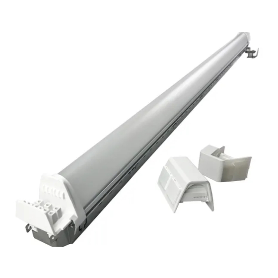
- Page 3 Components NOTE: Appearance of components may vary slightly depending on fixture being retrofitted. Brackets GE LED driver Wire clip Locking mechanism DC connector Bridge End caps Grommets and pins Tethers (optional) #8 hex head LED light engine drilling screws Fixture...
- Page 4 1.6” (as shown) from the tombstones. Blue Insert grommets in belly pan. Pass red and blue wires of the GE LED driver through the grommets (one wire per grommet).
- Page 5 NOTE: The following brackets use a locking mechanism. NOTE: All with tombstones come with one drilling screw. All brackets without tombstones come with two drilling screws. brackets Stationary tombstone Adjustable tombstone BRACKETS (A) OR (B) OR (C): Rotate the locking mechanism(s) on each bracket to the unlocked position as shown. Press down on both tabs at the same time Good...
- Page 6 NOTE: If connecting two 4ft LED light engines to one GE 90W LED driver, ensure that the light engines are oriented such that the black and red wires of both light engines are next to each other in the center of the fixture, such that the wires can reach the same connector.
- Page 7 NOTE: The following brackets use an alignment mechanism. Brackets below are for the following fixtures at different alignments: NOTE: For all fixtures, bracket must be screwed into belly pan of fixture. BRACKET A: For GENLYTE Alignment fixtures, align the outer most tabs with the outer walls of the tombstones.
- Page 8 Alignment For the above bracket, align the outer tabs with the outer walls of the tombstones. Bracket must be screwed into the belly pan of LSI 2 fixtures. Alignment For the above bracket, align the squared shaped tabs above the tombstones. Bracket must be screwed into the belly pan of HARRIS 2 fixtures.
- Page 9 **When connecting two 4ft LED light engines to one 90W GE driver. If not already connected, insert the blue wire from the GE LED driver into position “1” and the red wire into position “2” of the DC connector. Insert the black wire from the LED light engine into a position “1” and the red wire into the corresponding position “2”...
- Page 10 Wrap tether Tether eyelet around bracket Supporting ceiling member TETHER WILL BE PRE-INSTALLED ON THE BRACKET: Wrap the tether over a supporting ceiling member, and slip its loop around the fixture’s metal bracket. (Example shown; choose wrapping location wherever possible). The eyelet will be placed between the screw and the bracket (right).
- Page 11 Variation of the Fixture 2 Install only one end cap in the middle on each side of each light engine (top). NOTE: Ensure that connector and wires are located within end cap after installation. If wires are too long, push extra wire length back into grommet.
- Page 12 All trademarks are the property of their respective owners. Information provided is subject to change without notice. All values are design or typical values when measured under laboratory conditions. Current, powered by GE is a business of the General Electric Company. © 2018 GE.