
Related Manuals for Kathrein ALC


Summary of Contents for Kathrein ALC
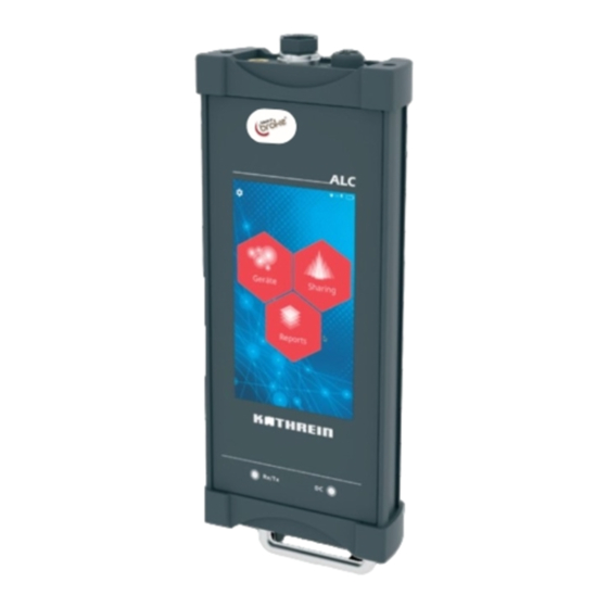
- Page 1 INSTRUCTIONS FOR USE ALC (Antenna Line Configurator) MOBILE COMMUNICATION Configuration and control of AISG antenna line products Version 4.0...
-
Page 2: Table Of Contents
6.1.1 Turning the ALC ON 6.1.2 Turning the ALC Off Putting the ALC into the Stand-by Mode Forcing a Hard Shutdown of the ALC Charging the Battery Connecting a PC to the ALC Installing Microsoft RNDIS Driver for Windows 7, 8, 10 18 Graphical User Interface 10.1... - Page 3 11.8 Download Manual 11.9 Download License Operating the ALC in the Devices Mode 12.1 Searching for an ALD 12.1.1 Selecting the AISG Protocol Scanning Options 12.2 Connecting to an ALD 12.3 Operating the Kathrein FlexRET 12.3.1 Configuring the FlexRET Subunits 12.3.2...
-
Page 4: General
● Retain the ALC product documentation and pass it on to the next owner. See data supplied in the memory of the ALC. To display the data on a PC, connect the ALC to the PC via USB and export the data. -
Page 5: Scope Of Delivery
● 1 x HF cable SMB/7-16, 1.8 m Intended Use The Antenna Line Configurator (ALC) must be used only to configure the RET system. The ALC offers the following functions: ● Configuration of AISG-compatible antennas (ALDs), such as RET and TMA ●... -
Page 6: About These Instructions
Overview These instructions for use contain all the information necessary to install and operate the Antenna Line Configurator (ALC). Keep these instructions for further reference, and if the unit passes to another owner, pass them on to the new owner. -
Page 7: Markings In The Text
Download button; downloads files from the ALC onto a USB stick Delete button; deletes a file Upload button; uploads a file from a USB stick onto the ALC Upload button; confirms, selects or deselects a setting Scan button; starts a scan Connect button;... -
Page 8: Abbreviations And Technical Terms
About These Instructions 2.3.3 Abbreviations and Technical Terms 3GPP 3rd Generation Partnership Project Antenna Clock Sensor Antenna Line Configurator Antenna Line Device AISG Antenna Interface Standards Group; RET systems are controlled using the AISG protocol. ALD Sensor ALD Temperature Sensor Geographic Location Sensor Graphical User Interface Remote Electrical Tilt: System for the remote control of the electrical tilt of an... -
Page 9: Preconditions For Operation
Preconditions for Operation ● Make sure that the RCUs and ALDs that are configured with the ALC are correctly installed and connected to the AISG bus. ● Make sure that each RCU is calibrated before the initial configuration of the inclination angle, after each manual adjustment to the inclination angle and each time the RCU is removed. -
Page 10: Controls And Connections
LED is lit: Data is being transmitted to the AISG bus ③ LED for the DC charging ● DC is lit in blue: ALC is in the stand-by mode ● DC is lit in yellow: ALC is turned on/off and the battery is being charged ●... -
Page 11: Performing The Initial Set-Up
Performing the Initial Set-Up When the ALC is switched on for the first time, the display shows the First Start Up : Fig. 2: First start-up screen when switching on for the first time ① ② 1. Adjust the Date and Time as required. -
Page 12: Operating The Alc
✔ The ALC is on. ► Press the On/off button to put the ALC into the stand-by mode. ➯ The ALC screen turns off and the LED for the DC charaging is blue. To turn on the ALC from the stand-by mode: ►... -
Page 13: Forcing A Hard Shutdown Of The Alc
Forcing a Hard Shutdown of the ALC ✔ The ALC is on. ► Press the On/off button for 20 seconds to force a hard shutdown of the device. ➯ The ALC shuts down. 936.4720d 13 of 94... -
Page 14: Charging The Battery
( in Fig. 8) is lit red. ► Immediately charge the battery. ► To save the battery, turn off the ALC when not using it for a longer time ✔ The ALC is on. ► Press the On/off button for 20 seconds to force a hard shutdown of the device. - Page 15 ● If there is too much last connected to the ALC, the following warning message appears: ● Fig. 5: Short circuit warning message ● If case of a short circuit, the following warning message appears: ● Fig. 6: Short circuit warning message 936.4720d...
-
Page 16: Connecting A Pc To The Alc
It is possibe to connect various devices with a Wi-Fi module to the ALC using Wi-Fi, e.g. a PC, laptop, tablet, phone etc. It is also possible to connect the ALC to a PC or laptop using a a micro USB cable. - Page 17 ✔ The connection to the ALC has been lost. If the connection to the ALC has been lost, the following message appears: Fig. 7: Battery warning 1. Make sure the Wi-Fi on the ALC is active. 2. Make sure the PC is connected to the ALC Wi-Fi hotspot.
-
Page 18: Installing Microsoft Rndis Driver For Windows 7, 8, 10
An RNDIS driver is a part of the Windows operating system, but the OS fails to detect it automatically. The following steps will help the user to install the RNDIS driver. 1. Connect the ALC to a device using the mini USB cable. ➯ The operating system automatically searches for the RNDIS driver. After the system fails to find the driver, the following message is shown: 2. - Page 19 11. Select Let me pick from a list of device drivers on my computer . ➯ A window will appear asking to select the device type. 12. Select Network adapters , as the RNDIS emulater a network connection: 13. Click Next . ➯...
- Page 20 Installing Microsoft RNDIS Driver for Windows 7, 8, 10 17. Click Yes . ➯ The following window appears: ➯ The RNDIS Kitl device is now installed and is ready to be used. 18. Click Close to finish the triber installation. 20 of 94 936.4720d...
-
Page 21: Graphical User Interface
● Example descriptions of the displays and controls of the GUI are given below. NOTE It is possibe to connect various devices with a Wi-Fi module to the ALC using Wi-Fi, e.g. a PC, laptop, tablet, phone etc. It is also possible to connect the ALC to a PC or laptop using a a micro USB cable. -
Page 22: Entering Values
Graphical User Interface 10.1.2 Entering Values In some cases, it is necessary to enter numbers or a combination of the letters and numbers. When the user presses on the corresponding field, a numerical or an alphanu- merical keyboard appears. Fig. 9: Numerical keypad for entering a number Fig. -
Page 23: Main Menu
10.2 Main Menu When the device is switched on, the main menu is displayed. All functions of the ALC can be accessed from here. ① Opens the menu for the general ALC settings, see ⇛ 11, p. 24 et seqq ②... -
Page 24: Showing And Changing The Ald Setup
⑧ ● opens the manual as a PDF file in a browser if opened on the PC ● saves the license on a USB stick if opened on the ALC, see ⇛ 11.7, p. 42 ⑨ ● opens the license as a PDF file in a browser if opened on the PC ⑩... -
Page 25: Mechanical Level
Mechanical Level To calibrate the mechanical downtilt: ✔ The ALC lies with its rear panel against an ALD, its level, vertical surface. 1. Tilt the ALC until the required downtilt is achieved. 2. Press the Save button to calibrate the internal inclination sensor of the ALC. -
Page 26: Network Configuration
Showing and Changing the ALD Setup 11.3 Network Configuration In the Network Configuration submenu it is possible to change the settings of the network configuration. ① turns the Wi-Fi on and off, see ⇛ 11.3.1, p. 26 ② changes the IP address, see ⇛ 11.3.2, p. 27 ③... -
Page 27: Changing The Ip Address
11.3.2 Changing the IP Address ① 1. Tap the IP address value field ( in Fig. 16). ② ➯ The numerical keyboard for entering numbers ( in Fig. 16) appears: Fig. 16: Network configuration: Changing the IP address 2. Either type in the new IP address or enter it using the numerical keyboard. ③... -
Page 28: Changing The Password
Showing and Changing the ALD Setup 11.3.3 Changing the Password ① 1. Tap the Password value field ( in Fig. 17). ② ➯ The alphanumerical keyboard for entering a new password ( in Fig. 17) appears: Fig. 17: Network configuration: Changing the password 2. -
Page 29: Selecting A Wi-Fi Channel
11.3.5 Selecting a Wi-Fi Channel ⑥ 1. Tap the Wi-Fi Channel field ( in Fig. 16). ➯ The drop-down menu with channels from 2–11 appears: Fig. 18: Network configuration: Selecting a Wi-Fi channel ① 2. Select a Wi-Fi channel from the drop-down menu ( in Fig. -
Page 30: System Information
⇛ 11.3.1, p. 26 ② updates the ALC firmware, see ⇛ 11.5.2, p. 33 ③ resets the ALC to factory settings, see ⇛ 11.5.3, p. 35 ④ manages the ALD files, see ⇛ 11.5.4, p. 36 Fig. 20: System configuration 30 of 94 936.4720d... -
Page 31: Changing Date And Time
11.5.1 Changing Date and Time ① 1. Tap the Date/Time submenu ( in Fig. 20). ➯ The following submenu opens: Fig. 21: System configuration: Changing the date and time 2. Tap the Date value field. ➯ The calender opens: 3. Select a date in the calender. 936.4720d 31 of 94... - Page 32 Showing and Changing the ALD Setup 4. Tap the Time value field. ➯ The following window appears: 5. Change the time (hours and minutes) pressing the down or up arrow. 6. At the end of all the changes made in the Date/Time submenu, press the Save button to ③...
-
Page 33: Updating The Alc Firmware
NOTE Before updating the ALC firmware, make sure to load the firmware update onto the USB stick. It is recommended that the firmware file is stored in the /alc-update directory of the USB stick for easier handling. ✔ A USB stick is plugged into the USB port on the ALC. - Page 34 ➯ During the update, the ALC turns off. ➯ If there is more than one update file in the update directory, the ALC will use the latest one. ➯ All connections to the ALC are lost during the update process.
-
Page 35: Resetting The Alc To Factory Settings
● you forgot Wi-Fi settings, e.g. password, ● the ALC must be reset to factory settings. NOTE Before setting the ALC to the factory settings, keep in mind that the following settings will be reset to the factory default settings: ● network settings, ●... -
Page 36: Managing Ald Files
11.5.4 Managing ALD Files NOTE Before uploading or downloading ALD files onto/from a USB stick, make sure to connect a USB stick with the corresponding files to the ALC. ④ 1. Tap the File Management ALD submenu ( in Fig. 20). - Page 37 Uploading/Downloading/Deleting ALD Files ④ 1. After having made all the selections in 11.5.4, p. 36, press in Fig. 25. ➯ The following page appears (on the example of the AISG 2 protocol, RET antenna and ALD Config Files ): Fig. 26: System configuration: File Management ALD, ALD Config Files ①...
-
Page 38: Fig. 29: Upload An Ald File: Folders
① 1. Press Upload ( in Fig. 27) to upload an ALD Config File from the USB stick onto the ALC. ➯ If there is no USB stick connected, the following warning message appears: Fig. 28: No USB connected message ➯... -
Page 39: Fig. 31: Download An Ald File: Folders
➯ If a USB stick is connected, the folders on the connected USB stick are shown: Fig. 31: Download an ALD file: Folders 2. Select a folder to download an ALD file into. 3. Press the Download button. ➯ The selected file is downloaded onto the USB stick from the ALC. 936.4720d 39 of 94... - Page 40 Showing and Changing the ALD Setup Deleting an ALD File ✔ ALD files have been selected on the ALC, see Uploading/Downloading/Deleting ALD Files , p. 37. 1. Press Delete to delete the selected file from the ALC. ➯ The selected file is deleted from the ALC.
-
Page 41: Changing User Configuration
11.6 Changing User Configuration In this submenu it is possible to change the user settings. ① enters the installer ID by means of the alphanumeric keyboard enters the installation company by means of the alphanu- ② meric keyboard ③ ① ②... -
Page 42: Performing Service
Performing Service NOTE The submenu Service is password protected for security reasons. To obtain the password, it is necessary to contact Kathrein. #gibt es eine Telefonnummer dafür? In this submenu it is possible to access tge AISG Bus logging. ①... -
Page 43: Fig. 34: Service: Confirm Password
➯ The following page appears: ① confirms the entered password Fig. 34: Service: Confirm password ① 4. Press the Confirm button ( in Fig. 34) to confirm the entered password. ➯ The following page appears: ① turns logging on and off ②... -
Page 44: Fig. 36: Service: Hdlc Logging - Selecting Log Files
Showing and Changing the ALD Setup 8. Confirm the file name by pressing the Save button on the alphanumerical keyboard. ➯ The HDLC logging starts automatically. All activities performed on the AISG bus are saved into a file. ① 9. Press in Fig. - Page 45 ① 11. To download the selected log files, press the Download button ( in Fig. 37). ➯ The the folders on the connected USB stick are shown. 12. Proceed as described in Downloading an ALD File , p. 39. ② 13.
-
Page 46: Download Manual
Showing and Changing the ALD Setup 11.8 Download Manual ✔ A USB stick is plugged into the USB port on the ALC. ⑧ 1. Tap Download Manual ( in Fig. 12). ➯ The folders on the connected USB stick are shown: Fig. -
Page 47: Download License
11.9 Download License Downloading the licenses onto a USB stick is carried out the same way as described in Download Manual , p. 46 . 936.4720d 47 of 94... -
Page 48: Operating The Alc In The Devices Mode
In this menu, it is possible to access and operate the ALDs connected to the ALC. 12.1 Searching for an ALD ✔ An ALD is connected to the ALC via the AISG port connector (HF or RS 485). ② 1. Tap Devices in the main menu, see in Fig. -
Page 49: Fig. 42: Devices: Ald Found
3. To select one or several ALDs, tick the boxes next to them ( in Fig. 42). ② 4. Press to open the protocol menu and change the protocol. ③ 5. Press to connect the ALC to the selected ALD. 936.4720d 49 of 94... -
Page 50: Selecting The Aisg Protocol Scanning Options
Operating the ALC in the Devices Mode 12.1.1 Selecting the AISG Protocol Scanning Options ► ② in Fig. 42 to open the AISG protocol scanning options. ➯ The following page appears: ① selects or deselects all scanning options ② selects or deselects individual scanning options ③... -
Page 51: Connecting To An Ald
Connecting : Fig. 45: Devices: Connecting to an ALD ➯ After the ALC has established a connection to the ALD, the Connect button is grey and it is possible to see the properties of the ALD and change some settings. -
Page 52: Operating The Kathrein Flexret
● is read by the ALC when scanning the AISG bus when connected to a FlexRET. ✔ The ALC has found the ALD and the ALD has been connected to the ALC, see 12.1, p. 48 and 12.2, p. 51. -
Page 53: Configuring The Flexret Subunits
12.3.1 Configuring the FlexRET Subunits ► ① in Fig. 47 to open the list with the individual subunits. ➯ The following page appears: ① shows the list of the individual subunits ② opens the properties of the selected subunit, see ⇛... -
Page 54: Fig. 49: Devices: Properties Of The Selected Subunit
Operating the ALC in the Devices Mode Showing Properties of the Selected Subunit ► ② in Fig. 48 to open the properties of the selected subunits. ➯ The following page appears: ① shows the subunit properties The values of the following fields are displayed and cannot be changed: ●... -
Page 55: Fig. 50: Devices: Changing Settings Of The Selected Subunit
For pre-configured RETs and FLEXRets, this option is deactivated. ⑤ shows the antenna serial number; it is possible to change the antenna serial number for RETs without an RFID tag or manufacturers other than Kathrein ⑥ changes the electrical downtilt ⑦ saves the changes Fig. -
Page 56: Fig. 51: Devices: Adding Subunit Properties
➯ The following page appears: ① selects the file ② downloads the file from the ALC onto the subunit is only active (the panel and the icon change from grey ① to red) if a file has been selected in Fig. -
Page 57: Changing The Flexret Settings
➯ The following page appears: ① opens the page to update the FlexRET firmware; it is only possible if a file has been uploaded onto the ALC in System Configuration / File Management ALD , see ⇛ Managing ALD Files , p. 36 opens the submenu to change the protocol mode, see ②... -
Page 58: Selecting The Report Type
Fig. 55: Devices: FlexRET: Changing the FlexRET protocol mode 12.3.3 Selecting the Report Type ALD reports is where the device data for the ALDs connected to the AISG bus is saved in the form of report files in the ALC internal memory. ► ④... -
Page 59: Operating The Kathrein Ret
12.4 Operating the Kathrein RET ✔ The ALC has found the ALD and the ALD has been connected to the ALC, see 12.1, p. 48 and 12.2, p. 51. ✔ The following is displayed: ① opens the list with the individual subunits, see 12.4.1, p. 60 ②... -
Page 60: Configuring The Kathrein Ret
Operating the ALC in the Devices Mode 12.4.1 Configuring the Kathrein RET ► ① in Fig. 57 to open the list with the subunits. ➯ The following page appears: ① shows the list of the subunits ② opens the subunit properties, see Showing Properties of the RET Subunits , p. -
Page 61: Fig. 59: Devices: Properties Of The Ret Subunit
Showing Properties of the RET Subunits ► ② in Fig. 58 to open the subunit properties. ➯ The following page appears: ① shows the subunit properties The values of the following fields are displayed and cannot be changed: ● Electric Downtilt, Tilt Range ●... -
Page 62: Fig. 60: Devices: Changing The Subunit Settings
Operating the ALC in the Devices Mode Changing the Subunit Settings ► ② in Fig. 59 to open the settings of the subunit. ➯ The following page appears: ① opens the submenu to enter the values for some RET properties, see ⇛ Adding the Antenna Properties , p. 63 updates the antenna Config file, see ⇛... -
Page 63: Changing The Ret Settings
Adding the Antenna Properties ► ① in Fig. 60 to open the list with the individual subunits. ➯ The following page appears: ① enters the sector ID ② enters the base station ID ③ enters the installer ID ④ enters the installation date ⑤... -
Page 64: Fig. 63: Devices: Changing Ret Properties
Operating the ALC in the Devices Mode ① opens the page to update the RET firmware; it is only possible if a file has been uploaded onto the ALC in System Configuration / File Management ALD , see ⇛ Managing ALD Files , p. 36 ②... -
Page 65: Selecting The Report Type
12.4.3 Selecting the Report Type ALD reports is where the device data for the ALDs connected to the AISG bus is saved in the form of report files in the ALC internal memory. ► ③ ④ in Fig. 57 or in Fig. -
Page 66: Operating The Kathrein Tma
Operating the ALC in the Devices Mode 12.5 Operating the Kathrein TMA ✔ The ALC has found the ALD and the ALD has been connected to the ALC, see 12.1, p. 48 and 12.2, p. 51. ✔ The following is displayed: ①... -
Page 67: Fig. 67: Devices: Properties Of The Tma Subunit
Showing Properties of the TMA Subunits ► ② in Fig. 66 to open the subunit properties. ➯ The following page appears: ① shows the subunit properties The values of the following fields are displayed and cannot be changed: ● RX Frequency Band ●... -
Page 68: Fig. 68: Devices: Changing The Tma Subunit Settings
Operating the ALC in the Devices Mode Changing the TMA Subunit Settings ► ② in Fig. 67 to open the settings of the subunit. ➯ The following page appears: ① changing the gain ② changing the mode between Active and Bypass ③... -
Page 69: Changing The Tma Settings
➯ The following page appears: ① opens the page to update the RET firmware; it is only possible if a file has been uploaded onto the ALC in System Configuration / File Management ALD , see ⇛ Managing ALD Files , p. 36 ②... -
Page 70: Selecting The Report Type
Operating the ALC in the Devices Mode 12.5.3 Selecting the Report Type ALD reports is where the device data for the ALDs connected to the AISG bus is saved in the form of report files in the ALC internal memory. ► ③... -
Page 71: Operating The Alc In The Sharing Mode
In this menu, it is possible to access and operate the site-sharing adapter connected to the ALC. 13.1 Searching for an Site-Sharing Adapter ✔ An site-sharing adapter is connected to the ALC. ③ 1. Tap Sharing in the main menu, see in Fig. 11. -
Page 72: Fig. 74: Sharing: Site-Sharing Adapter Information
⇛ 13.3, p. 74 ⑤ closes the page and returns to the main menu Fig. 75: Sharing: Site-sharing adapter information - error 4. Contact Kathrein to receive a new XCD.xml file. 72 of 94 936.4720d... -
Page 73: Creating A Site-Sharing Report
13.2 Creating a Site-Sharing Report ► ① in Fig. 74. ➯ The following page appears: ① enters remarks enters a a file name; the date and the installer ID is added to the file name automatically if the installer ID ②... -
Page 74: Configuring The Site-Sharing Adapter Settings
Operating the ALC in the Sharing Mode 13.3 Configuring the Site-Sharing Adapter Settings ► ④ in Fig. 74 to open the site-sharing adapter settings. ➯ The following page appears: ① opens the Password Options , see ⇛ 13.3.1, p. 75 ②... -
Page 75: Operating Password Options
13.3.1 Operating Password Options ► ① in Fig. 77 to opend the Password Options . ➯ The following page appears: ① sets a password, see ⇛ 13.3.1, p. 75 ② deletes the password, see ⇛ 13.3.1, p. 75 ③ changes the password, see ⇛ 13.3.1, p. 75 shows whether the password has been activated in the Password Options ●... -
Page 76: Fig. 80: Sharing: Password Options - Saving A New Password
Operating the ALC in the Sharing Mode 5. Tap the Repeat New Password field. 6. Enter the password again by means of the alphanumeric keyboard. ③ 7. Confirm the password by pressing the tick ( in Fig. 79). ➯ The page looks as follows: ①... -
Page 77: Fig. 82: Sharing: Password Options - A New Password Has Been Set
① enteres the password ② confirms that the password has been entered correctly Fig. 82: Sharing: Password options - a new password has been set Deleting the Password ② 1. Tap in Fig. 78. ➯ The following page appears: ① enters the current password ②... -
Page 78: Fig. 84: Sharing: Password Options - Setting A New Password
Operating the ALC in the Sharing Mode Changing the Password ③ 1. Tap in Fig. 78. ➯ The following page appears: ① enters the old password ② enters the new password ③ re-enters the new password ④ confirms that the password has been entered corectly Fig. -
Page 79: Creating Ald And Site-Sharing Reports
TEST_2015-10-14_08-30-23.txt. ● The date ant time at which the report has been created are determined automatically by the ALC. ● The Filename is part of the ALD report. It is possible to enter 56 characters for the file- name. If the installer ID has been set in Setup ▶ User Configuration ▶ Installer ID , it is set as a filename ●... -
Page 80: Managing Ald Reports
Creating ALD and Site-Sharing Reports 14.1.1 Managing ALD Reports NOTE The filenames of the report files will display the installer ID if it has been previ- ously set in Setup ▶ User Configuration ▶ Installer ID . For instance, in the example below, the installer ID has been set to LAD . -
Page 81: Fig. 87: Reports: Ald Reports
① downloads the selected files onto a USB stick ② deletes the selected files ③ closes the page and returns to the previous menu Fig. 87: Reports: ALD reports 936.4720d 81 of 94... -
Page 82: Managing Site-Sharing Reports
Creating ALD and Site-Sharing Reports 14.1.2 Managing Site-Sharing Reports ② 1. Tap Site-Sharing Reports ( in Fig. 85) to open ALD reports. ➯ A list with the reports is displayed: ① selects all files ② selects one or several files ③... -
Page 83: Disposal
Disposal Dispose of this product in accordance with all national legislation and regulations. Electronic equipment is not domestic waste – in accordance with directive 2002/96/EC OF THE EUROPEAN PARLIAMENT AND THE COUNCIL dated 27 January 2003 on waste electrical and electronic equipment – and it must be disposed of properly. -
Page 84: Appendix
Agreement, then customer shall pay the cost of the audit. 1.4 Customer shall not make any modifications to Licensed Software or remove any proprietary notices of Kathrein or third parties found in or on the Licensed Software. Customer shall not translate, reverse engineer, decompile, disassemble or reverse assemble Licensed Software or try, directly or indirectly, to obtain or create source code of the Licensed Software except to the extent that such prohibition may be unenforceable under applicable law. - Page 85 5.3 Except for the cases expressly set forth in section 5.2, Kathrein‘s liability shall be limited to a maximum amount of two (2) license fee per single event and to an aggregate amount of four (4) license fees for the entire term of the agreement. Moreover Kathrein shall not be liable for any inci-...
-
Page 86: Fcc Statements
Appendix 16.2 FCC Statements Warning Statements FCC § 15.21 Changes or modifications not expressly approved by the manufacturer could void the user’s authority to operate the equipment. Statement FCC § 15.19 This device complies with Part 15 of the FCC rules. Operation is subject to the following two conditions: (1) This device may not cause harmful interference, and (2) this device must accept any interference received, including interference that may cause undesired operation. -
Page 87: Adresses
Adresses For questions about markerting, contact: Fax: +49 8031 184-820 E-mail: central.sales@kathrein.de RET hotline for technical information: Fax: +49 8031 184-973 E-mail: antennas.mobilcom@kathrein.de 936.4720d 87 of 94... - Page 88 88 of 94 936.4720d...
- Page 89 936.4720d 89 of 94...
- Page 90 90 of 94 936.4720d...
- Page 91 936.4720d 91 of 94...
- Page 92 List of figures List of figures Fig. 1: Structure of the ALC Fig. 2: First start-up screen when switching on for the first time Fig. 8: Navigating within a sub-menu Fig. 9: Numerical keypad for entering a number Fig. 10: Alphanumerical keypad for entering a number/letter Fig.
- Page 93 Fig. 58: Devices: Configuring the RET antenna Fig. 59: Devices: Properties of the RET subunit Fig. 60: Devices: Changing the subunit settings Fig. 61: Devices: Adding antenna properties Fig. 62: Devices: RET properties Fig. 63: Devices: Changing RET properties Fig. 64: Devices: RET – Selecting a report type Fig.
- Page 94 KATHREIN SE Anton-Kathrein-Straße 1-3 83022 Rosenheim, Germany Phone +49 8031 184-0 Fax +49 8031 184-820 www.kathrein.com | mobilcom@kathrein.de...