Advertisement
Quick Links
Introduction
This is the GE Alliance Arming Station Installation Instructions
for models AL-1111 (four-line LCD) and AL-1116 (four-line
LCD with Smart Card reader). These units are used with Alliance
control panels to control security system alarm and access func-
tions. Features include:
• Beeper.
• Integrated tamper switch.
• Four-line liquid crystal display (LCD).
• Multiple text formats.
• Embedded Smart Card reader (AL-1116 only).
• Access and system status LEDs.
• One open collector output to drive a small relay (an external
UL Listed power supply is required for UL installations).
• One input for an egress function.
• Plastic hinged cover.
The unit may be used up to 5,000 ft. (1.5 km) from the control
panel or 4 door/elevator controller DGP.
Note:
An external UL Listed power supply is required for UL
installations.
Installation
To install the unit, do the following:
1.
The cover is hinged at the bottom. To open, grasp the cover
at the sides or the top and pull gently. The cover will swing
down on its pins (Figure 1). To remove the cover, gently pry
one of the pins away from the body of the unit and pull.
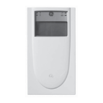
Figure 1. Unit front
Status LEDs
LCD screen
Keypad
Area LEDs
Cover
Alliance Arming Station • AL-1111, AL-1116
Installation Instructions
2.
The metal mounting plate at the back of the unit is held by a
locking screw (Figure 2). To remove the mounting plate,
loosen the screw by at least 0.3 in. (8 mm), slide the
mounting plate down, and then pull the bottom of the
mounting plate away from the body of the unit.
Figure 2. Unit back and mounting plate
Cable
entry
Terminals
DIP
switches
Cable
entry
Tamper
switch
3.
Attach the mounting plate to the mounting surface using the
three screws provided.
4.
Set the RAS address using DIP switches 1 though 4 (see
DIP switch settings
5.
Set the system bus termination switch using DIP switch 5, if
required.
6.
Wire the COMMS system bus cabling (see
page 2).
Note:
All power should be turned off to the control panel before
wiring the unit.
7.
Insert plastic cable entry blanking plugs (provided) into the
back of the unit to blank any unused cable entry channels
(Figure 2).
8.
Place the unit onto the mounting plate and move the unit
down about 0.3 in. (8 mm) to lock in place.
9.
Tighten the locking screw at the base of the unit until firm.
This will also ensure that the tamper switch (Figure 2) is
properly secured. Do not overtighten the screw.
1048520C • September 2006
Copyright © 2006, GE Security Inc.
Locking screw
on page 2).
Wiring
Mounting
plate
Mounting
holes
Cable
entry
on
Advertisement

Related Manuals for GE AL-1111


Summary of Contents for GE AL-1111
- Page 1 The metal mounting plate at the back of the unit is held by a locking screw (Figure 2). To remove the mounting plate, This is the GE Alliance Arming Station Installation Instructions loosen the screw by at least 0.3 in. (8 mm), slide the...
-
Page 2: Tamper Switch
Alliance Arming Station Installation Instructions Tamper switch Wiring The back tamper switch (Figure 2 on page 1) must be secured to Use the terminal block (Figure 5) on the back of the unit to wire work correctly. Make sure that the tamper switch remains the COMMS system bus connection. -
Page 3: Operating Features
Operating features Egress control and open connector (IN and OUT) You can optionally use the IN and OUT terminals for egress The unit includes the following features: control and door relay operation. Keyboard backlight and night light. By default the IN. - Page 4 5. Reserved The programming menu is structured in two sections: Menu 5 is reserved for future development. • Menus 1 to 6 are common to both AL-1111 and AL-1116 models. 6. Factory defaults • Menus 7 to 12 apply only to the AL-1116 model.
-
Page 5: Offline Mode
9. Protocol options Use this option to select the method the AL-1116 reader sends data to the panel. Wiegand. Smart Card data is transmitted in the Wiegand protocol (default). When user cards are programmed, the AL-1623 programmer sets the number of bits (26 or 27). -
Page 6: Specifications
Maximum operating current 270 to 300 mA Normal operating current This device may not cause harmful interference. AL-1111 26 mA at 13.8 VDC This device must accept any interference received, including AL-1116 35 mA at 13.8 VDC interference that may cause undesired operation.