Table of Contents
Advertisement
Advertisement
Table of Contents

Related Manuals for GE CS5500


Summary of Contents for GE CS5500
- Page 1 CS875-575-275-175 Alarm system CS5500 Programming Manual September 2003...
- Page 2 Aritech is a GE Interlogix brand. www.aritech.com Copyright (c) 2003 GE Interlogix B.V.. All rights reserved. GE Interlogix B.V. grants the right to reprint this manual for internal use only. GE Interlogix B.V. reserves the right to change information without notice. 1045335...
-
Page 3: Table Of Contents
Introducing the CSx75 system......................6 Getting Started ........................... 6 1.1.1 Welcome ........................6 1.1.2 Default codes....................... 6 LCD keypad (CS5500)........................ 7 Other methods of programming ....................8 Programming the system........................9 Powering up the system ......................9 Entering programming mode ...................... 9 2.2.1 Changing the user interface language ................. - Page 4 Programming the wireless modules ..................28 6.4.1 Defaulting the wireless modules ................28 6.4.2 Programming the wireless detectors................28 Reading the event log ........................29 Reference ............................30 Appendix 1: Reporting fixed codes in Contact ID or SIA ............30 Appendix 2: Overview of module numbers ................
- Page 5 IST OF TABLES Table 1 Default codes ............................. 6 Table 2 Required settings for up/downloading ....................17 Table 3 UDx75 menu paths .......................... 20 Table 4 A sample system..........................25 Table 5 Event description ..........................29 Table 6 Event codes ............................. 31 Table 7 Module numbers ..........................
-
Page 6: Introducing The Csx75 System
It can be expanded as required with additional boards. The new menu driven keypad, the CS5500, allows you to program the system easily using a menu structure. If you are using a different keypad, see the relevant manual for programming information. -
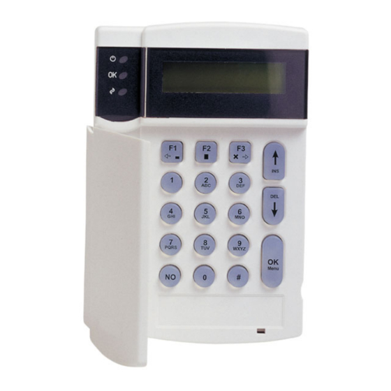
Page 7: Lcd Keypad (Cs5500)
The brackets contain the additional digits for 6-digit codes. LCD keypad (CS5500) The CS5500 LCD keypad allows you to program the CSx75 system using a menu structure. • Power (green) On if the system is connected to the mains and the battery is OK. -
Page 8: Other Methods Of Programming
• Press to delete text. Other methods of programming You can use the CS5500 keypad to program the system without the menu system. This mode uses devices, locations and segments. To program in this mode using the CS5500 keypad: •... -
Page 9: Programming The System
ROGRAMMING THE SYSTEM Powering up the system When the CS5500 if powered up for the first time, the language, keypad defaults, partition and keypad must be set. These options must also be set each time a keypad is defaulted. •... -
Page 10: Selecting A Menu Option
Press OK at the system prompt. Press the keys to enter and navigate the command menu. Selecting a menu option • Press OK to select a menu option and move forward in the menu structure. • Press NO to reject a menu option and move backwards in the menu structure. •... -
Page 11: Changing Phone Numbers And Phone Prefixes
• Press a number key to clear the current value and display the value of the key pressed. • Press to increase the current value by one. • Press to decrease the current value by one. • Press ## to clear the current value to 0. Press the number keys to enter the value. -
Page 12: Programming Map
Programming map The highest level of the menu structure is outlined below. The full menu structure can be found in the Menu Structure included in your language kit. It provides a complete overview of all modules and programming entries and should be used as a reference tool when programming the system. - Page 13 CS535 Voice Module Recording Playback Handshake Digit Kiss Off Digit Model Version Default Settings CS1700 Proximity Readers Prox Reader n CS7001 GSM Module Central Station Autotest GSM Options Model Version Default Settings Commands Alarm Memory Reset Smoke Detector Service Check Do Self Test Event Log Outputs...
-
Page 14: Editing Text
DITING TEXT Overview The CSx75 has a text editor that includes a word library. You can use this editor to change the text of certain programmable text options. Navigate with the keys to the relevant menu option and press OK. Press OK to select the language you want to edit. -
Page 15: Installer Message
• To accept a shortened version of the word, press F3 to accept the word. Then move the cursor to the unnecessary characters and press to delete them. • To reject the word, continue entering text as normal. • Press the keys to scroll through the list of word library words. -
Page 16: Programming With The Udx75 Software
SOFTWARE Other methods of programming You can program the system using the CS5500 keypad or the UDx75 software. This software allows you to download the programming information on the control panel to the computer running the UDx75 software, change it and upload the changes from the computer to the panel. -
Page 17: Programming With Up/Download Software
To use the UDx75 software with a modem connection: Follow steps 1 - 5 on page 16. Make sure that the modem settings are correct. For more information about modem settings, see the UDx75 Online Help. Select Download>Connect> Connect Using AMD. A message box opens saying Initializing modem. -
Page 18: Programming Tasks
4.3.1 Programming tasks You can perform all available programming tasks using the UDx75 software. Table 3 shows the UDx75 menu path for each task. Task UDx75 menu option Adding customer notes View>Customers>Notes Adding operators Program>Setup>Add/Change operators Backing up the database Tools>Backup database Changing a customer record View>Customers>Single customer... - Page 19 Task UDx75 menu option Importing a database Tools>Import database Loading the default settings Advanced>Default Control data Logging in Start>Programs>UDX75>UDX75 Printing a customer record list Program>Print preview>Customer list Printing a program log Program>Print preview>Program log Printing a programming worksheet Program>Print preview>Programming worksheet Printing an operator list Program>Print preview>Operator list Printing customer notes...
-
Page 20: Table 3 Udx75 Menu Paths
Task UDx75 menu option Setting the outputs Advanced>Auxiliary outputs Setting the TCP/IP settings Program>Setup>TCP/IP Settings Setting the timed functions Advanced>Timed functions Setting the zone type Advanced>Zone types Setting up a customer record View>Customers>Single customer Setting up a modem Program>Setup>Modem setup Setting up answering machine defeat Program>Setup>AMD setup Specifying the direct connect settings... -
Page 21: Advanced Programming
DVANCED PROGRAMMING Multi-area mode You can program a keypad to act as a single-area keypad or a multi-area keypad by default. A single-area keypad allows the user to arm one area only while a multi-area keypad allows the user to arm one or more areas. A user with rights can change a single- area keypad to a multi-area keypad and vice versa. -
Page 22: Setting Up A Communicator
Repeat these steps to set other languages. Setting up a communicator The CSx75 supports different modes of reporting events to multiple central stations. There are six phone numbers - each phone number has it own account code, protocol and events. The configured prefix is common to all six phone numbers. If a four-second delay is specified in the prefix, the panel does not look for a dial tone, but performs blind- dialling. -
Page 23: Dual Reporting
Level 1 Level 2 Value State Account Code Phone Number 1 445566 Phone Number 2 445566 Protocol Phone Number 1 Phone Number 2 Events Phone Number 1 – Alarms Enabled Phone Number 1 – Alarm Restores Enabled Phone Number 1 – Tampers and Restores Enabled Phone Number 2 –... -
Page 24: Split Reporting
5.5.4 Split reporting Split reporting configures the control panel to report to two different central stations. Some events must be reported to phone number 1 and others to phone number 2. The control panel dials the first number twice. If it cannot reach this number, it dials the second number twice. -
Page 25: Programming A Sample System
ROGRAMMING A SAMPLE SYSTEM The sample system This chapter explains how to program a basic system using the tasks and settings outlined in Table 4. More information on installing a basic system can be found in the Installation Manual. Enter 1122 to silence the keypad if it starts beeping during programming. -
Page 26: Setting The System Date And Time
Enter the partition number and press OK. In this case, enter 1. The keypad prompts you to enter the keypad number. Enter the keypad number and press OK. In this case, enter 1. The system prompt appears. Repeat the above steps for each keypad connected to the system. The partition number and keypad number prompts are displayed for the initial setting only. -
Page 27: Defining The Country Code
6.2.5 Defining the country code The control panel is shipped with software that contains different country default settings. Changing the value or selecting a country code configures the panel with the corresponding country defaults. Navigate with the keys to Country Code and press OK. The current country is displayed. -
Page 28: Programming The Wireless Modules
10. Press ## to leave the programming mode. The OK to Exit prompt is displayed. The system now functions as a normal alarm system. See the CS5500 LCD Keypad User Manual for information on arming and disarming the system. -
Page 29: Reading The Event Log
EADING THE EVENT LOG The event log displays the details of all the events that occur from when you turn the system on. A maximum of 512 events are held in the event log. For a list of all possible events, see page 46. -
Page 30: Reference
EFERENCE Appendix 1: Reporting fixed codes in Contact ID or SIA Table 6 lists the event codes sent for different reports (if enabled) when using Contact ID or SIA formats. The numbers in brackets following the event is the number that is reported as the zone number. -
Page 31: Table 6 Event Codes
Report Contact ID Report Contact ID Aux power over current Partial close (device number) Aux power restore Zone activity fault (device number) Low battery (device Zone activity restore number) Low battery restore Fail to close (device number) Mains fail (device RF jamming number) Mains restore (device... -
Page 32: Appendix 2: Overview Of Module Numbers
Appendix 2: Overview of module numbers Every keypad, expansion module and wireless receiver module has a module number. Module Module number CSx75 CS534 Two-way Listen-In CS535 CS7001 Table 7 Module numbers 8.2.1 CS1700 door swipe module Learn-in sequence Module number Learn-in sequence Module number Table 8 CS1700 module numbers... -
Page 33: Cs208/Cs216 Input Expander
8.2.3 CS208/CS216 input expander DIP switch setting Starting Module DIP switch setting Starting Module zone number zone number number number = ON = OFF Table 10 CS208/CS216 module numbers 8.2.4 CS208H input expander Starting Module DIP switch setting Starting Module zone number zone... -
Page 34: Cs507 Output Module
Starting Module DIP switch setting Starting Module zone number zone number switch setting number number = ON = OFF Table 11 CS208H module numbers 8.2.5 CS507 output module DIP switch setting Module number DIP switch setting Module number = ON = OFF Table 12 CS507 module numbers 8.2.6 CS320 power supply module... -
Page 35: Rf433 Receiver Module
DIP switches 1-3 set the address of the CS320. DIP switch 4 controls the tamper feature. On enables tamper. Off disables tamper. 8.2.7 RF433 receiver module Module Module DIP switch setting DIP switch setting receiver number receiver number (default) = ON = OFF DIP switch 4 is not used Table 14 RF433 module numbers... -
Page 36: Appendix 3: Output Events
Appendix 3: Output events The control panel, the CS507 output expander and the CS320 power module each have selectable output events that trigger the output. Table 15 to Table 17 list these events. Event Event Event Misc Keypads Alarms Any Bypass Keypad Fire Burglary Alarm Duress... -
Page 37: Table 17 Cs507 Output Expander Output Events
Events 49 and 50 require RX8w8, RX16w8, RX32w8, RX8i4, RX16i4, or RX48i4 wireless receivers to operate. If set to latched condition, these events are one second When Event 48 is programmed, it is possible to program a user code's authorization to select which output(s) a particular code activates. Always program Event 39, Fire alarm reset, to follow the event. -
Page 38: Table 18 Cs320 Power Module Output Events
See Schedule Times>Opening and Schedule Times>Closing/Autoarm. If set to latched condition, these events are one second Events 46 and 47 require RX8w8, RX16w8, RX32w8, RX8i4, RX16i4, or RX48i4 wireless receivers to operate. Events 48, 49 and 50 arm or disarm the CSx75 at the open (disarm) or close (arm) time for the appropriate schedule. -
Page 39: Appendix 4: Communicator Formats
Appendix 4: Communicator formats One of several communicator formats can be used to transmit to the receiver connected to phone number 1. Consult the instructions for your central station receiver to determine which format is compatible. Table 18 lists the selectable communication formats. Format Description Contact ID SIA with area modifiers... -
Page 40: Appendix 5: Service Messages
Appendix 5: Service messages The keypad displays service messages as a result of manual and automatic tests. Table 19 lists each message and outlines the action you should take to resolve the problem. Message Definition Action Control There has been interference with the Ensure that the casing is mounted correctly Box Tamper control panel casing. -
Page 41: Table 20 Service Messages
Message Definition Action Expansion The expansion module has detected an Check the module for wiring faults. Over-Current excessive amount of current being drawn from one of its outputs and has disabled the output as a means of protection. Expansion The mains power supply is not connected Reconnect the mains power supply and Power Trouble to an expansion module power supply. -
Page 42: Appendix 6: Tasks Summary
Appendix 6: Tasks summary Task Installer Master user User No code Condition* Adjusting the LCD contrast Answer an up/download call Arm and disarm the system If authority allows. Bypass a zone If authority allows. Configure home automation devices Control home automation devices Engineer tamper reset If enabled for... -
Page 43: Appendix 7: Event Log Events
Appendix 7: Event log events Event message Explanation Alarm An alarm has been tripped. Alarm Restore See Alarm event message. Autotest An autotest message was sent to the central station. B-Alarm A full alarm on a B zone type that is considered a burglary alarm. Box Tamper A box tamper. - Page 44 Event message Explanation Enrolled Modules are enrolled on the bus. The module numbers are recorded. Exit Error An exit door remained open after the exit delay expired. Expander Trouble A problem with an expander module. Expander Trouble See Expander Trouble event message. Restore Expansion Event A bus device generated an event to report conditions not described by other events.
- Page 45 Event message Explanation PA Panic Alarm A personal attack alarm has been tripped. Panic Keypad A panic alarm generated by pressing the keys 7 and 9 on the keypad. Partarm See Partial Arm event message. Partial Arm Part arm of the system by a specific user. Recent Closing An alarm occurred within five minutes of the panel being armed.
-
Page 46: Appendix 8: Word Library Words
Event message Explanation Zone Lost An RF transmitter has lost the supervision with the wireless receiver. This happens when the transmitter has not reported its supervision message to the RF receiver within the long supervision window. See appendix 5. Zone Lost Restore See Zone Lost event message. -
Page 47: Glossary
LOSSARY Term Definition Keypad Function A menu entry that groups keypad options that enable home automation commands. The commands activate the primary function of a keypad. These options are With PIN and Without PIN. 200Bd FSK Channel A menu option that sets the channel used by the selected zone, zone type or event for 200Bd FSK protocol. - Page 48 Term Definition Advanced Menu A menu option that activates certain options in the Installer menu structure. The following menus are enabled only if the Advanced Installer menu is enabled. (Installer) (i) Zone Types (ii) Communicator>Format Override (iii) This keypad>Zone Type Names (iv) Device/Location Programming (v) CS7001 GSM Module>Phone Line Cut (vi) CS7001 GSM Module...
- Page 49 Term Definition ARC (alarm report The place to which the control panel reports alarms and other events (such as, centre) system faults, opening/closing and diagnostic events). The ARC is also known as a control station or a central station. ARC Dial Attempts A menu option that specifies the number of dial attempts (1 to 15 attempts) that the communicator makes when reporting to the central station.
- Page 50 Term Definition Auto Bypass A menu option that automatically bypasses interior follower zones if no exit is detected during the exit delay time. The exit is detected by the opening and closing of an entry/exit zone. Autotest A menu entry that groups options that configure the automatic test run by the system.
- Page 51 Term Definition Batt Dynamic Test A menu option that sets the length of time that the control panel performs the Duration Dynamic Battery test. This can be between 0 to 255 minutes where 0 is no test. Batt Presence Test A menu option that enables a test to determine whether the battery is connected to the system.
- Page 52 Term Definition Bypassed zones Zones that are excluded when the rest of the system is armed. They can be entered without triggering an alarm. Call Back Code A menu option that specifies the code that starts a listen-in session when the panel is in call back mode.
- Page 53 Serial printer or Home Automation Protocol. Contact ID Code A menu option that specifies the contact ID code to be used when reporting the selected zone type. The Contact ID codes are listed in the CS5500 Programming Manual. Control Panel A menu entry that groups all options relating to the central processing unit of the alarm system.
- Page 54 Term Definition CS534 Listen-in Module A two-way audio voice communicator. If the control panel communicates an alarm, the audio module allows the central station to establish a two-way session or monitor the premises for listen-in purposes. CS535 Voice Module A module used to send pre-recorded voice messages when activated. CS586 Direct Connect A menu optional device used to interface the up/download software directly to the Module...
- Page 55 Term Definition Direct Connect Module See CS586 Direct Connect Module Disable on Listen-in A menu option that disables the selected output during listen-in time. This option is normally used to silence sirens during listen-in. After the listen-in session, the sirens are activated again. Disarm A menu option that enables the disarm function for the selected proximity reader action.
- Page 56 Term Definition Duress Code A code that disarms the system and activates a duress alarm. This is a silent alarm that sends a special report to the central station. Dynamic Batt Test at A menu option that enables a dynamic battery test at arming. This is an automatic Arming test carried out by the control panel at the moment of arming to ensure the battery is working properly.
- Page 57 Term Definition Exit Error A menu option that specifies that the control panel sends an exit error report if an entry/exit zone is faulted when the exit delay expires. This report is sent along with the user number that armed the system, if the panel is not disarmed before the entry delay expires.
- Page 58 Term Definition Factory defaults The default control panel values that are set in the factory. Each country has a country code and associated default values. To use these values, default the panel and then select the country code. The default values are filled into the control panel the moment the country code is selected.
- Page 59 Term Definition Fn Function A menu option that specifies the function of the selected function key. Possible functions are: • Arm Away (asks for code if quick arm disabled) • Arm Stay • Bypass Zones (asks for code if required for bypass) •...
- Page 60 Term Definition GSM Connection A menu entry that groups GSM connection settings. GSM Engine Info A menu entry that groups information that is returned from the on-board GSM module on the CS7001 GSM module. GSM Module See CS7001 GSM Module GSM Operator A menu entry that groups information on the current GSM operator and allows a specific GSM operator to be manually selected.
- Page 61 Term Definition Interface Configuration A menu option that enables interface configuration transition broadcasts. These broadcasts transmit changes to zones, partitions and so on to the home automation system. (Transition Broadcasts) A menu option that enables the control panel to respond to interface configuration requests sent by the home automation system.
- Page 62 An overview of the keypad numbers and their module numbers can found in appendix 2 of the CS5500 Programming Manual. Keypad Panic A menu entry that groups the report codes sent for the keypad panic event.
- Page 63 Term Definition Last Round Count A menu option that displays the number of rounds of RF data received during the last transmission. This information can provide an indication of the quality of data reception. To get an accurate count, the installer must cause a tamper and then wait 5 seconds before restoring the tamper to prevent additional signals being counted.
- Page 64 This can be either 500 ms or 50 ms. Lost Clock Indication A menu option that enables the service message ‘Control Loss of time'. See appendix 5 in the CS5500 Programming Manual for a list of all service messages.
- Page 65 Term Definition Low Battery A menu option that sounds keypad buzzers when a low battery event occurs. (Sound On) A menu option that enables low battery reporting on the control panel. (System Reports) A menu entry that groups report codes sent to the central station for a low battery event.
- Page 66 Term Definition Medical/Aux 2 (4+6) A menu option that activates keys 4 and 6 as the medical alarm combination keys. When this option is enabled and these keys are pressed at the same time, a medical alarm is generated. Mic A at Startup A menu option that activates microphone A when listen-in commences.
- Page 67 Term Definition Only if Open A menu option that causes an output to activate only if the programmed event occurs between the opening and closing time of a schedule. Open zone A detection area that is not secured. An open zone makes the system status ‘Not Ready’.
- Page 68 Term Definition Partarm A menu option that groups the report codes sent to the central station when the system is partarmed (Arm Stay). See also Arm Stay mode Partition A group of zones which operate as a unit and can be armed and disarmed independently of other partitions in the system.
- Page 69 Term Definition Phone Line Cut A menu option that sends a report is sent to the central station the moment the phone line cut is restored. If a CS7001 GSM module is installed, it may be configured to report the phone line cut straight away. (System Reports) A menu entry that groups options that activate the internal siren when a phone line is cut while armed or disarmed.
- Page 70 Term Definition Program/Download A menu option that reports programming and up/download events to the selected phone number. (Phone Number) A menu option that reports programming and up/download events to the central station depending on the condition of the panel dialler. (CS7001 GSM Module) See also Panel Dialler OK Events and Panel Dialler Not OK Events Programming A menu entry that groups home automation commands.
- Page 71 Term Definition Reporting A menu option that indicates that the CS7001 GSM module is currently reporting events to the panel via the GSM network. (CS7001 GSM Module) A menu entry that groups reporting options. (Communications) A menu entry that groups reporting options for the selected zone type. (Zone Types) Reports A menu entry that groups report options for the selected module.
- Page 72 Term Definition RF Sensor Lost and A menu option that sends a report to the selected phone number when an RF Restores sensor is missing. A restore report is sent to the central station when the receiver receives a valid signal from the lost transmitter. (Phone Number) A menu option that enables RF sensor lost and restores reporting on a CS7001 GSM module depending on the condition of the panel dialler.
- Page 73 If Master Code Resets Tamper Memory is enabled, a master user can reset the service message by entering a master user code. See appendix 5 in the CS5500 Programming Manual for more information on service messages. Service Message A menu option that enables or disables the service messages on the keypad.
- Page 74 Term Definition The Security Industry Association format. It is an FSK 300 baud format. SIA with Area Modifier is a version of the SIA format that sends partition information in addition to the event information. A special version of SIA, called XSIA, is used in Holland. XSIA combines user names and zone descriptors with the SIA codes when reporting events.
- Page 75 The CSx75 can be configured to report events to one or more phone numbers. Each phone number has an event selector to program which events are reported to each number. See Setting up a communicator in the CS5500 Programming Manual for more information. Start Learning A menu command that triggers the learn-in mode.
- Page 76 Term Definition Supervision A menu entry that groups wireless supervision options. There are three options: Short Window, Normal Window and Fire Window. PIR and door/window sensors follow short and normal windows. If a PIR or door/windows sensor does not report within the time specified in Short Window, the system does not allow the user to arm the system.
- Page 77 Term Definition Telephone line monitor A menu option that monitors the voltage and current of the telephone line to detect a faulted phone line. If a fault is found, the panel sends a report to the central station when the phone line fault is fixed and the phone line can be used again. TELIM Channel A menu option that specifies that the TELIM channel format is used to report the selected zone, zone type or event.
- Page 78 A menu option that sets the voice message to be reported for the selected zone type or event. The channel corresponds to one of the 15 pre-recorded voice messages. See the CS5500 Installer Manual for more information on the voice module. See also All in Sequence Voice Module...
- Page 79 Term Definition Word Library A menu option that enables the word library. This is a predefined collection of words that speed up text editing. As the user/installer types a character, the keypad automatically displays a matching word. The word library is enabled by default.
- Page 80 Term Definition Zone Inactivity Monitor A zone characteristic that sends a report to the central station when the zone does not change conditions within a specified time period. (Zone Types) A menu option that sends a report to the selected phone number when a zone inactivity event occurs.
- Page 81 Term Definition Zone/User A menu option that sets the zone/user number that is used to send an SIA message when a Bus communication error occurs. The parameters, SIA Code, Partition and Zone/User provide flexibility to define the SIA Code and partition and zone/user.
-
Page 82: Index
CS208H module numbers........34 Multi-area mode ..........21 CS275............6, 16 Navigating menus ..........9 CS507 module numbers ........34 Output events CS5500............6, 7, 16 Control panel ..........36 CS575............6, 16 CS320 power module ........38 CS586..............16 CS507 output expander......... 37 CS590 cable ............16 Phone settings .......... - Page 84 1045335...