Garmin G5 Installation Manual
Electronic flight instrument, part 23 aml stc
Hide thumbs
Also See for G5:
- Install manual & pilot's manual (238 pages) ,
- Installation manual (175 pages) ,
- User manual (168 pages)

Related Manuals for Garmin G5


Summary of Contents for Garmin G5
- Page 1 Garmin G5 Electronic Flight Instrument Part 23 AML STC Installation Manual 190-01112-10 December 2019 Revision 21 Page 1...
- Page 2 Garmin. Garmin hereby grants permission to download a single copy of this manual and of any revision to this manual onto a hard drive or other electronic storage medium to be viewed...
- Page 3 08/20/2019 Added Piper Altimatic IIIC Autopilot to approved interfaces. Various typographical errors corrected. 12/12/2019 Added GNC 355, Density Altitude annunciator. Various typographical errors corrected. Garmin G5 Electronic Flight Instrument Part 23 AML STC Installation Manual 190-01112-10 Rev. 21 Page 3...
- Page 4 California's Proposition 65. If you have any questions or would like additional information, please refer to our web site at www.garmin.com/prop65. WARNING Perchlorate Material – special handling may apply, See www.dtsc.ca.gov./hazardouswaste/ perchlorate. Garmin G5 Electronic Flight Instrument Part 23 AML STC Installation Manual 190-01112-10 Rev. 21 Page 4...
- Page 5 The G5 has an operating temperature range of -4˚F to 140˚F (-20˚C to +60˚C). The G5 will prevent operation from the battery when the battery is outside of this temperature range.
-
Page 6: Table Of Contents
5.3 G5 (ADI) with a GPS Antenna ..................... 109 5.4 G5 (ADI) with GPS Position Input ....................111 5.5 G5 (ADI) and GMU 11 with GPS Position Input ................115 5.6 G5 (ADI or DG), GMU 11 and GPS Antenna ................119 5.7 G5 (HSI) with VHF Navigator ....................... - Page 7 Figure 3-2 Correct CAN Bus Wiring Example and Node Connections ............33 Figure 3-3 Incorrect CAN Wiring Example ....................34 Figure 3-4 CAN Bus Termination (011-02887-00) for G5, GMU 11, and GAD 13 ........34 Figure 3-5 CAN Bus Termination for GAD 29/29B ..................35 Figure 3-6 CAN Bus Termination for G5 on M27500 Wire .................
- Page 8 Figure 4-30 Trimmed Adapter Plate ......................61 Figure 4-31 Adapter Plate Mounting Holes ....................62 Figure 4-32 Dual G5 Panel Cutout - Using Match Drilled Holes for Reference .......... 62 Figure 4-33 Instrument Panel After Cutout for Dual Vertical G5 Units ............63 Figure 4-34 Adapter Plate Installed ......................
- Page 9 Figure 5-3 G5 (ADI) with a GPS Antenna ....................109 Figure 5-4 G5 (ADI) with GPS Position Input .................... 111 Figure 5-5 G5 (ADI) and GMU 11 with GPS Position Input ..............115 Figure 5-6 G5 (ADI or DG), GMU 11 and GPS Antenna ................119 Figure 5-7 G5 (HSI) with VHF Navigator ....................
- Page 10 Figure 5-20 G5 (HSI) with GPS Navigator ....................164 Figure 5-21 Dual G5 with Two-Inch GPS Navigator ................. 168 Figure 5-22 Dual G5 with Two-Inch GPS Navigator Notes ............... 169 Figure 5-23 G5 (ADI) with Two-Inch GPS Navigator ................173 Figure 5-24 G5 (ADI) with Two-Inch GPS Navigator Notes ..............
- Page 11 Figure 6-42 Dual Vertical Stabilizer With Low Horizontal Stabilizer Zoning ..........283 Figure 6-43 Example Lightning Zoning for Single-Engine Aircraft ............284 Figure 6-44 Example Lightning Zoning for Twin-Engine Aircraft .............. 285 Garmin G5 Electronic Flight Instrument Part 23 AML STC Installation Manual 190-01112-10 Rev. 21...
- Page 12 Table 3-2: Contents of the GMU 11 Installation Kit (011-04349-90) ............27 Table 3-3: Contents of the G5, GMU 11, and GAD 13 Connector Kits (011-03002-00/10) ....... 28 Table 3-4: Contents of the GAD 29/29B Connector Kit (011-03271-00) ............ 28 Table 3-5: G5 Adapter Plate ........................
-
Page 13: General Description
G5(s) in the existing instrument panel. In the attitude application, the Garmin G5 indicator can serve as an attitude indicator or rate-of-turn indicator. The G5 can also serve as a DG or HSI, either standalone or in combination with a G5 attitude display. -
Page 14: Acronyms And Abbreviations
GNS 400W Series Installation Manual 190-00356-08 GNS 500W Series Installation Manual 190-00357-08 Garmin G5 Electronic Flight Instrument Part 23 AML STC Maintenance Manual 190-01112-11 including Instructions for Continued Airworthiness Pilots Guide, Garmin G5 Electronic Flight Instrument, Part 23 AML STC... -
Page 15: Stc Permission
Aviation /General Aviation/Flight Instruments & Indicators/G5 page. Select ‘Software” in the overview tab. ** The GAD 29B is only required in installations that utilize the G5 heading and course output to an autopilot, or interface with a Garmin navigator. -
Page 16: System Overview
G5 Attitude Indicator 1.6.1 The G5 Electronic Flight Instrument configured as an attitude indicator, is shown in Figure 1-1. The G5 is an electronic instrument display operating as a standalone flight display. It features a bright, sunlight readable, 3.5-inch color display which is sized to fit in a standard 3-1/8-inch instrument cutout. The G5 contains integrated attitude/air data sensors that provide display of attitude and secondary display of air data information. - Page 17 1.6.1.5 Air Data The G5 unit is connected to the aircraft Pitot / Static system and optionally connected to the GAD 13 for Outside Air Temperature (OAT) information. See section 4.1.2.4 for details. The G5 functions provided by the air data are shown below: •...
-
Page 18: Figure 1-2 G5 Standby Battery
1.6.1.6 Standby Battery The standby battery is required. The G5 has an externally mounted lithium – ion battery that sustains the G5 flight display with up to 4 hours of emergency power. Figure 1-2 G5 Standby Battery 1.6.1.7 G5 Attitude Interfaced to GMU 11 The GMU 11 magnetometer can be installed as an optional interface for a standalone G5 attitude display. -
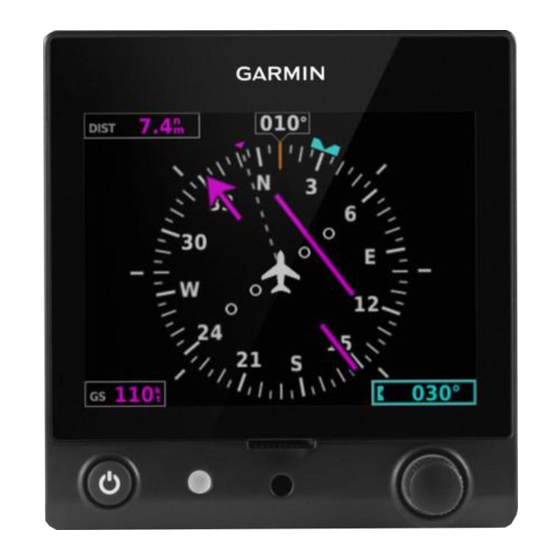
Page 19: Figure 1-3 G5 Electronic Flight Instrument (Dg/Hsi)
The G5 has battery backup and in the case of aircraft power loss will sustain G5 operation with up to 4 hours of emergency power. When the G5 is installed as a DG/HSI the battery backup is optional. - Page 20 The G5 DG can be used as a backup Attitude/Airspeed/Altitude Indicator. 1.6.2.2 G5 HSI VHF NAV For installations where the G5 HSI is being used for basic VHF NAV, the G5 HSI is installed with a GNC255 or SL30. •...
- Page 21 1.6.2.5 Backup Attitude Indicator All of the functions listed in 1.6.1 are also available by selecting the G5 HSI Menu via the knob and selecting PFD. 1.6.2.6 G5 DG/HSI Interface Summary • Aircraft Power and Ground • Aircraft Pitot/Static •...
-
Page 22: Figure 1-5 Gad 29/29B
*Excitation Pass Through *GAD29B only For the G5 Attitude and/or G5 DG/HSI installation the GAD 29/29B will receive ARINC 429 data from the navigators interfaced and transmit that information onto the CAN bus to be consumed by the G5. The GAD 29/29B can run on 14VDC or 28VDC. The GAD 29/29B can also receive OAT information over the CAN bus to be converted to ARINC 429 data and transmitted to the navigators. -
Page 23: Figure 1-6 - Glare Shield Mounted Gps Antenna
G5 which provides position, velocity, and time data to support various functions. This antenna requires Garmin part number 330-01754-00 to connect to the G5. If the primary G5 is installed as an ADI, HSI, or DG and not connected to a WAAS enabled GPS source, the G5 must be connected to this antenna. -
Page 24: Figure 1-8 - Gtp 59 (Temperature Probe)
GTP 59 1.6.7 The Garmin GTP 59 is an externally mounted temperature probe that provides raw outside air temperature data. The device is a three-wire temperature probe interface with a pre-installed wire lead that is 10 feet long. Figure 1-8 – GTP 59 (Temperature Probe) -
Page 25: Technical Specifications
GAD 13 (includes OAT Average/Max Current Draw @ 14 VDC .120 A probe) Average/Max Current Draw @ 28 VDC .050 A This area intentionally blank Garmin G5 Electronic Flight Instrument Part 23 AML STC Installation Manual 190-01112-10 Rev. 21 Page 25... -
Page 26: Limitations
VDC or 28 VDC • if a G5 is being installed as an attitude indicator and an existing attitude indicator is retained, the G5 pointer type must be configured to match the existing indicator pointer type o Fixed Pointer Type / G5 Config = Ground o Movable Pointer Type / G5 Config = Sky •... -
Page 27: Installation Overview
The connector kit P/N 011-03002-10 is required to be ordered separately for a GAD 13 installation. For the G5 and GMU 11, the connector kit P/N 011-03002-00 is part of the LRU’s associated installation kit. Garmin G5 Electronic Flight Instrument Part 23 AML STC Installation Manual 190-01112-10 Rev. -
Page 28: Table 3-3: Contents Of The G5, Gmu 11, And Gad 13 Connector Kits (011-03002-00/10)
Contact, Pin, Military Crimp, Size 20 336-00024-00 The item listed in Table 3-5 will be supplied when a G5 DG/HSI is ordered. The adapter plate is used whenever a G5 is installed and any instrument panel modification has taken place or a G5 is installed in an instrument hole with cutouts for instrument knobs. - Page 29 • Flat braid, 1/16” (AA59569F36T0062 or equivalent) • Tubing and fittings are required to connect pitot and static air to the G5. Pitot and Static plumbing parts are aircraft specific, see Section 4.1.5. • 120Ω CAN cable, see section 3.4.5 for more information. There are two options for this wire.
-
Page 30: Test Equipment
Aircraft grade fasteners e.g., AN525 screws, MS20426AD rivets, MS21059 rivet nut plates, MS21071 reduced rivet spacing nut plates. NAS1832, NAS1834, or NAS1836 potted inserts maybe required if honeycomb core panels are used to support the installation of G5 components. •... - Page 31 G5 DG/HSI over the CAN bus. If a GPS Navigator or a GTX 3x5 is used for a GPS signal, disable the internal GPS receiver of the G5. If the G5 is connected to the Glare Shield Mounted GPS Antenna, enable the internal GPS receiver. See Section 5 for configuration settings.
-
Page 32: Table 3-7: G5 And Supporting Lru Circuit Breaker Labels
Turn Coordinator position should be labelled #2 ATT. Alternate spellings of “ATT” is acceptable. [2] When a single G5 is installed, the GMU 11 is powered from the same breaker as the G5. When two G5s are installed, the GMU 11 is powered from the same breaker as the G5 in the DG/HSI position. -
Page 33: Figure 3-1 Can Bus Backbone
3.4.5.2 CAN Bus The primary digital interface used to exchange data between the G5 Electronic Flight Instrument, GMU 11, GAD 29/29B, and GAD 13 is the Controller Area Network, also known as the CAN bus. CAN was developed by Bosch GmbH in the 1980s, and its specifications are currently governed by ISO 11898-2. -
Page 34: Figure 3-3 Incorrect Can Wiring Example
Termination resistors are provided either via termination adapters that plug into an LRU’s CAN connection, a resistor internal to the LRU or a 120Ω resistor installed into the wiring harness at a G5 if the G5 is the end of the CAN bus backbone. -
Page 35: Figure 3-5 Can Bus Termination For Gad 29/29B
For excess coax cable, coil as necessary and use cable ties to secure coil. Do not attempt to shorten the pre-installed lead on the Glare Shield Mounted GPS Antenna. Garmin G5 Electronic Flight Instrument Part 23 AML STC Installation Manual 190-01112-10 Rev. - Page 36 Cooling Requirements 3.4.6 While no forced cooling air is required for the G5, GMU 11, GAD 29/29B, or GAD 13 it is highly recommended that the air behind the panel be kept moving (by ventilation or a fan). Units tightly packed in the avionics stack heat each other through radiation, convection, and sometimes by direct conduction.
-
Page 37: Figure 3-7 Gad 29B Inline Transformer Mounting Instructions
MIL-C-27500 installations that do not use the G5 as a CAN bus terminator, see Figure 3-8 and Figure 3-9. • Method B should be used for resistor installations that use the G5 as a terminator and are utilizing shielded twisted-pair cable, MIL-C-27500, see Figure 3-10 and Figure 3-11. •... -
Page 38: Figure 3-8 G5 Diode And Resistor Method A Buildup
Section 3.2.1. Figure 3-9 shows the placement requirements of the resistors on the CAN bus wiring. Figure 3-13 shows the placement requirements of the diode on the G5 power wire. See Section 5 for complete wiring interconnect details. -
Page 39: Figure 3-9 Method A Placement Of G5 Can Bus Resistors
Figure 3-9 Method A Placement of G5 CAN Bus Resistors Garmin G5 Electronic Flight Instrument Part 23 AML STC Installation Manual 190-01112-10 Rev. 21 Page 39... -
Page 40: Figure 3-10 Method B G5 Resistor Preparation
Note: The “-Y” character is for color of heat shrink, color of heat shrink is the installer’s choice. 3. Mark heatshrink with resistor value in permanent ink. Garmin G5 Electronic Flight Instrument Part 23 AML STC Installation Manual 190-01112-10 Rev. 21... -
Page 41: Figure 3-11 Method B Placement Of Can Bus Components
3. Secure the resistors together in the wire bundle as shown above. Note: The “-Z” character in the cable tie P/N is for color, color of cable tie is the installer’s choice. Garmin G5 Electronic Flight Instrument Part 23 AML STC Installation Manual 190-01112-10 Rev. 21... -
Page 42: Figure 3-13 Placement Of G5 Power Diode (Bothe Wire Types)
Figure 3-8 shows the installation procedure for the diode into the wiring harness. For part numbers of diode, see Section 3.2.1. Figure 3-13 shows the placement of the diode on each power input for the G5. See Section 5 for complete wiring interconnect details. Figure 3-13 Placement of G5 Power Diode (Bothe Wire Types) -
Page 43: Installation Procedures
Section 4.1.2.4 for more information. • Two Adapter Plates must be used if installing the G5 in an instrument hole with any cutout for instruments knobs. See Figure 4-10 and Figure 4-12 for more information. One or two G5s may be installed. See Figure 4-1 for typical installation configurations in an IFR approved aircraft. -
Page 44: Figure 4-1 Typical G5 Installations For Ifr Approved Aircraft
Figure 4-1 Typical G5 Installations for IFR Approved Aircraft A G5 can be installed in an instrument panel that does not have an existing attitude indicator or DG/HSI. In these cases, the G5 must be located on the Pilot’s instrument panel, and centered as nearly as practicable about the vertical plane of the pilot’s forward vision. -
Page 45: Figure 4-2 G5 Mounting Ring
Figure 4-2 G5 Mounting Ring Figure 4-3 Maximum Misalignment of the G5 in the Lateral Axis Garmin G5 Electronic Flight Instrument Part 23 AML STC Installation Manual 190-01112-10 Rev. 21 Page 45... -
Page 46: Figure 4-4 Maximum Misalignment Of The G5 In The Longitudinal Axis
Figure 4-4 Maximum Misalignment of the G5 in the Longitudinal Axis Figure 4-5 Maximum Misalignment of the G5 in the Vertical Axis Garmin G5 Electronic Flight Instrument Part 23 AML STC Installation Manual 190-01112-10 Rev. 21 Page 46... -
Page 47: Figure 4-6 G5 Alignment Pin
G5 Installation The G5 is installed by inserting the alignment pin located at the top of the unit into the mating hole in the mounting ring, pushing the unit flush with the instrument panel, and fastening the captive 3/32” hex socket head screw to the mounting ring as shown in Figure 4-6. -
Page 48: Figure 4-8 G5 Captive Mounting Screw Replacement
6-8 in-lb. of torque to the #4-40 mount plate screws. NOTE: Standard #6-32 hex socket head screws use a 7/64” hex drive feature. The access hole in the G5 bezel is large enough to accommodate this increase in hex tool size. -
Page 49: Figure 4-9 Required Vertical Spacing Between G5 Units
The panel may be modified by enlarging one hole or both, up to a maximum of 0.25 inch per instrument hole. The proposed positions must be such that neither G5 unit is obscured by the glareshield, control yoke or other object. -
Page 50: Figure 4-11 G5 Adapter Plate
The G5 Adapter Plate, (115-02642-00) is shown in Figure 4-11. Each installation of a G5 in a DG/HSI will include 2 adapter plates. Two G5 adapter plates must be installed as shown in Figure 4-12 when • any instrument panel modification has taken place •... -
Page 51: Figure 4-13, G5 Instrument Hole Dimensions
4.1.2.5 Cutting a New Instrument Hole for G5 Installation For G5 installations in aircraft approved for VFR-only operation, there may be the need to cut a new instrument hole. If it is desired to mount the G5 recessed, refer to Section 4.1.2.6 for instructions and limitations. -
Page 52: Figure 4-14, Clearance For Connections
4.1.2.6 G5 Recessed Mount Option The G5 unit may be recessed into the instrument panel which positions the display flush with the instrument panel. A full understanding of this modification is required before starting. A recessed adapter plate and modification of the instrument panel will be needed. Some instrument panels may not be capable of supporting this modification. -
Page 53: Figure 4-16 Recessed Adapter Plate Template Reference Holes
4.1.2.6.1 Recess Mounting Single G5 Install a single recessed G5 as illustrated by Figure 4-17 and Figure 4-18. A G5 installation in the attitude position is shown, but the same instructions can be used when installing a G5 in the DG or turn coordinator positions. -
Page 54: Figure 4-17 Single G5 Recessed Adapter Plate Installation
Figure 4-17 Single G5 Recessed Adapter Plate Installation Install G5 unit per section 4.1.2.2. Figure 4-18 Single G5 Recessed Installation Garmin G5 Electronic Flight Instrument Part 23 AML STC Installation Manual 190-01112-10 Rev. 21 Page 54... -
Page 55: Figure 4-19 Dual Vertical G5 Recessed Adapter Plate Installation
1.5D edge distance minimum. Figure 4-19 Dual Vertical G5 Recessed Adapter Plate Installation Install G5 units per section 4.1.2.2. Figure 4-20 Dual Vertical G5 Recessed Installation Garmin G5 Electronic Flight Instrument Part 23 AML STC Installation Manual 190-01112-10 Rev. 21 Page 55... -
Page 56: Figure 4-21 Dual Horizontal G5 Recessed Installation
4.1.2.6.3 Recess Mounting Dual G5 Horizontally In an installation where the G5 Attitude indicator is in the Turn Coordinator position and a G5 DG/HSI is installed as well (ref Figure 4-21), the dual G5s may be installed recessed horizontally in a similar manner to the dual vertical recessed installation. -
Page 57: Figure 4-22, Instrument Panel Limitations
4.1.2.6.4 Instrument Panel Modification Limitations The modification required for recess mounting a G5, whether it is single, dual vertical or dual horizontal must meet the following conditions: 1) The mounting location must satisfy the alignment requirements shown in Figure 4-3, Figure 4-4, Figure 4-5. -
Page 58: Figure 4-23 Instrument Panel - View Looking Forward
Figure 4-23 Instrument Panel - View Looking Forward Figure 4-24 Instrument Panel - View with Instruments Removed Temporarily remove instruments adjacent to proposed G5 location and/or as needed. Garmin G5 Electronic Flight Instrument Part 23 AML STC Installation Manual 190-01112-10 Rev. -
Page 59: Figure 4-25 Recessed Adapter Plate Located On Panel
Figure 4-26 Match Drilling Through Panel - Using Adapter Plate as Template When ready, mark adapter plate and match drill instrument panel 4x, .098 diameter through adapter plate reference holes Garmin G5 Electronic Flight Instrument Part 23 AML STC Installation Manual 190-01112-10 Rev. 21... -
Page 60: Figure 4-27 Preliminary Trimming Of Adapter Plate
Figure 4-27 Preliminary Trimming of Adapter Plate Figure 4-28 Adapter Plate Located on Far Side of Instrument Panel Use reference holes from adapter plate to align adapter plate behind panel. Garmin G5 Electronic Flight Instrument Part 23 AML STC Installation Manual 190-01112-10 Rev. 21... -
Page 61: Figure 4-29 Additional Trimming Of Adapter Plate Required
Figure 4-30 Trimmed Adapter Plate Trim adapter plate as needed; remove only enough material to allow adapter plate to fit without interference. Garmin G5 Electronic Flight Instrument Part 23 AML STC Installation Manual 190-01112-10 Rev. 21 Page 61... -
Page 62: Figure 4-31 Adapter Plate Mounting Holes
Drill 6 mounting holes through both adapter plate and panel; maintain minimum 1.5D edge distance for No. 6 hardware. Figure 4-32 Dual G5 Panel Cutout - Using Match Drilled Holes for Reference Garmin G5 Electronic Flight Instrument Part 23 AML STC Installation Manual 190-01112-10 Rev. -
Page 63: Figure 4-33 Instrument Panel After Cutout For Dual Vertical G5 Units
Figure 4-33 Instrument Panel After Cutout for Dual Vertical G5 Units Figure 4-34 Adapter Plate Installed Deburr and finish instrument panel and adapter plate as needed, then install adapter plate per Section 4.1.2.6.1 or 4.1.2.6.2. Garmin G5 Electronic Flight Instrument Part 23 AML STC Installation Manual 190-01112-10 Rev. -
Page 64: Figure 4-35 Dual Vertical G5 Units Installed
Figure 4-35 Dual Vertical G5 Units Installed Install G5 units per Section 4.1.2.2. This area intentionally blank Garmin G5 Electronic Flight Instrument Part 23 AML STC Installation Manual 190-01112-10 Rev. 21 Page 64... -
Page 65: Figure 4-36 G5 Flush Mount Adapter Plate Printable Template
The figure above may be photocopied and scaled as needed to match the full size part. This paper copy may be used along with the instructions on Section 4.1.2.6.5 to verify the proposed installation of the G5 units will meet the installation requirements. - Page 66 AMS-QQ-A-250/5. b) Material shall be minimum 0.032 inch thick. c) Material shall have some type of corrosion protection (primer, alodine, etc.) Garmin G5 Electronic Flight Instrument Part 23 AML STC Installation Manual 190-01112-10 Rev. 21 Page 66...
-
Page 67: Figure 4-37 Gmu 11 Pitch And Roll Requirements
The GMU 11 must be oriented with the mounting flanges facing down to within 3.0° of the aircraft pitch and roll axis as show in Figure 4-37. Figure 4-37 GMU 11 Pitch and Roll Requirements This area intentionally blank Garmin G5 Electronic Flight Instrument Part 23 AML STC Installation Manual 190-01112-10 Rev. 21 Page 67... -
Page 68: Figure 4-38 Gmu 11 Heading Alignment Requirements
If the magnetic interference cannot be remedied, another location should be chosen and tested. This area intentionally blank Garmin G5 Electronic Flight Instrument Part 23 AML STC Installation Manual 190-01112-10 Rev. 21... -
Page 69: Figure 4-39 Gmu 11 Mounting Hardware
APPENDIX D. Use the hardware called out in Figure 4-39 to mount the GMU 11. Figure 4-39 GMU 11 Mounting Hardware Garmin G5 Electronic Flight Instrument Part 23 AML STC Installation Manual 190-01112-10 Rev. 21 Page 69... -
Page 70: Table 4-2 Gad 29/29B, Gad 13 Supporting Hardware
Using the hardware called out in Figure 4-40 and Figure 4-41, mount the GAD 29/29B and GAD 13, respectively, to the chosen mounting location. Recommended torque of fasteners is 20-25 in-lbs. Garmin G5 Electronic Flight Instrument Part 23 AML STC Installation Manual 190-01112-10 Rev. -
Page 71: Figure 4-40 Gad 29/29B Mounting Hardware
Standard Part; Any MS (Mil-Spec) Part Number Nutplates Nuts MS21044N08 Rivets MS20426AD3-X Countersunk Screws #8 MS24693-XXX Washers NAS1149FN832P Nuts MS21044N08 Figure 4-40 GAD 29/29B Mounting Hardware Garmin G5 Electronic Flight Instrument Part 23 AML STC Installation Manual 190-01112-10 Rev. 21 Page 71... -
Page 72: Figure 4-41 Gad 13 Mounting Hardware
Pneumatic Connections 4.1.5 The G5 Attitude indicator and G5 DG/HSI use pitot and static pressure for the secondary display of altitude and airspeed. The installer must install the necessary hoses and fittings to interface to the existing aircraft pitot and static pressure source. Below are guidelines to use for this installation. - Page 73 Use appropriate tubing and fittings to connect the pitot and static lines to the unit. Avoid sharp bends in the tubing and route hoses clear of aircraft control cables. The G5 must not be at the low point of the pneumatic plumbing lines to avoid moisture or debris collecting at or near the unit.
-
Page 74: Figure 4-42 - Glare Shield Mounted Gps Antenna Dimensions
A TNC/BNC Adaptor (P/N 330-01754-00) is required to connect the GPS antenna to the G5. Figure 4-42 – Glare Shield Mounted GPS Antenna Dimensions... -
Page 75: Figure 4-43 - Glare Shield Mounted Gps Antenna (Screw-Mounted Installation Example)
Figure 4-43 – Glare Shield Mounted GPS Antenna (Screw-mounted Installation Example) Garmin G5 Electronic Flight Instrument Part 23 AML STC Installation Manual 190-01112-10 Rev. 21 Page 75... -
Page 76: Figure 4-44 - Glare Shield Mounted Gps Antenna (Hook & Loop Installation Example)
2.5 mΩ with the remote end connector disconnected. The GTP 59 can only be installed in lightning zones 2A or 3, per APPENDIX F. Garmin G5 Electronic Flight Instrument Part 23 AML STC Installation Manual 190-01112-10 Rev. -
Page 77: Figure 4-45 - Gtp 59 Oat Probe Dimensions
GTP 59 probe. The probe must be located no closer to the inlet edge than the width of its narrowest opening. Garmin G5 Electronic Flight Instrument Part 23 AML STC Installation Manual 190-01112-10 Rev. -
Page 78: Figure 4-46 - Gtp 59 Mounting (Aircraft With Metallic Skin Example)
0.5 inches of clearance maintained between the GTP 59 probe/terminal lug and any conductive element of aircraft structure. Typical installation examples are shown in Figure 4-47 and Figure 4-48. Garmin G5 Electronic Flight Instrument Part 23 AML STC Installation Manual 190-01112-10 Rev. 21... -
Page 79: Figure 4-47 - Gtp 59 Mounting - Composite Aircraft (Non-Conductive Access Panel)
(e.g., engine exhaust, direct sunlight, cabin exhaust, etc.) to provide an accurate air temperature measurement. Figure 4-47 – GTP 59 Mounting - Composite Aircraft (Non-conductive Access Panel) Garmin G5 Electronic Flight Instrument Part 23 AML STC Installation Manual 190-01112-10 Rev. 21... -
Page 80: Figure 4-48 - Gtp 59 Mounting - Composite Aircraft (Conductive Access Panel)
Figure 4-48 – GTP 59 Mounting - Composite Aircraft (Conductive Access Panel) Garmin G5 Electronic Flight Instrument Part 23 AML STC Installation Manual 190-01112-10 Rev. 21 Page 80... -
Page 81: Electrical Installation
See Section 3.2.1 for required circuit breaker part numbers. Use the following guidance for which electrical bus the G5 needs to be connected (Note: some aircraft manufacturers may label the battery bus as “essential bus” or “main bus”): •... - Page 82 Chapter 11 Section 17. Route and secure the wiring harness away from sources of electrical interference. The tables below list the parts required to complete the assembly of the G5, GMU 11, GAD 29/29B, and GAD 13 wiring harness connectors. Some of the parts required for this installation are included in the connector kit, and some are to be provided by the installer.
-
Page 83: Table 4-4: G5 (1P51, 2P51), Gmu 11 (P111), And Gad 13 (P131) Connector Parts
Table 4-4: G5 (1P51, 2P51), GMU 11 (P111), and GAD 13 (P131) Connector Parts Item Description Part Number Notes Shield Termination, Solder Style, Insulated, Heat-Shrinkable, AS83519/1-X Environment Resistant (X = size) (SAE-AS83519) Contact, Socket, MIL Crimp, Size 20 M39029/63-368, or... -
Page 84: Table 4-5: Gad 29/29B 9-Pin (P291) Connector Parts
1. AS83519/1-X and braid are the preferred method for shield termination. Alternately, AS83519/2- X with pre-installed shield drain may be used. 2. Garmin Part Number. Included in kit p/n 011-03271-00. This area intentionally blank Garmin G5 Electronic Flight Instrument Part 23 AML STC Installation Manual 190-01112-10 Rev. 21 Page 84... -
Page 85: Table 4-6: Gad 29/29B 25-Pin (P292) Connector Parts
1. AS83519/1-X and braid are the preferred method for shield termination. Alternately, AS83519/2- X with pre-installed shield drain may be used. 2. Garmin Part Number. Included in kit p/n 011-03271-00. This area intentionally blank Garmin G5 Electronic Flight Instrument Part 23 AML STC Installation Manual 190-01112-10 Rev. 21 Page 85... -
Page 86: Figure 4-49 Wiring Harness Connector Assembly
Figure 4-49 Wiring Harness Connector Assembly This area intentionally blank Garmin G5 Electronic Flight Instrument Part 23 AML STC Installation Manual 190-01112-10 Rev. 21 Page 86... -
Page 87: Figure 4-50 Shield Termination Methods
4. Slide a shield terminator (1) onto the exposed shield braid and insert shield braid drain (14) into shield terminator. Secure the shield terminator and braid drain to the shield using a heat gun approved for use with solder sleeves. Garmin G5 Electronic Flight Instrument Part 23 AML STC Installation Manual 190-01112-10 Rev. 21... - Page 88 13. Install the connector backshell cover (9) using the supplied screws (10). This area intentionally blank Garmin G5 Electronic Flight Instrument Part 23 AML STC Installation Manual 190-01112-10 Rev. 21...
-
Page 89: Weight And Balance
4.4 Electrical Load Analysis If the current draw of the G5 unit(s), GMU 11, GAD 29/29B, or GAD 13 is less than the removed equipment, then the aircraft’s electrical load capacity can be shown to be adequate by analysis. If it is... -
Page 90: Table 4-8: Sample Net Electrical Load Change Calculation
This assumes the electrical system was within all limits prior to the G5, GMU 11, GAD 29/29B, or GAD 13 installation. Record the new electrical load calculations. Table 4-8: Sample Net Electrical Load Change Calculation... - Page 91 5. Identify whether each load is used in a particular phase of flight for emergency operation. As a minimum, these systems generally include: o COM Radio #1 o NAV Radio #1 o Transponder and associated altitude source Garmin G5 Electronic Flight Instrument Part 23 AML STC Installation Manual 190-01112-10 Rev. 21 Page 91...
-
Page 92: Figure 4-51 Ammeter Placement For Current Measurements
10. Set the lighting as described below. These settings will be used for every current measurement which follows: o Set instrument panel and flood lights to maximum brightness. o Set displays with a backlight to 50% brightness Garmin G5 Electronic Flight Instrument Part 23 AML STC Installation Manual 190-01112-10 Rev. 21 Page 92... - Page 93 Electrical loads in excess of 80% but not greater than 95% of electrical system capacity are permitted during the takeoff/landing phase of flight when landing light(s) are switched on. This area intentionally blank Garmin G5 Electronic Flight Instrument Part 23 AML STC Installation Manual 190-01112-10 Rev. 21...
-
Page 94: Figure 4-52 Blank Electrical Load Tabulation Form, Sheet 1 Of 2
Figure 4-52 Blank Electrical Load Tabulation Form, Sheet 1 of 2 Garmin G5 Electronic Flight Instrument Part 23 AML STC Installation Manual 190-01112-10 Rev. 21 Page 94... -
Page 95: Figure 4-53 Blank Electrical Load Tabulation Form, Sheet 2 Of 2
Figure 4-53 Blank Electrical Load Tabulation Form, Sheet 2 of 2 Garmin G5 Electronic Flight Instrument Part 23 AML STC Installation Manual 190-01112-10 Rev. 21 Page 95... -
Page 96: Figure 4-54 Sample Completed Electrical Load Tabulation Form, Sheet 1 Of 2
Figure 4-54 Sample Completed Electrical Load Tabulation Form, Sheet 1 of 2 Garmin G5 Electronic Flight Instrument Part 23 AML STC Installation Manual 190-01112-10 Rev. 21 Page 96... -
Page 97: Figure 4-55 Sample Completed Electrical Load Tabulation Form, Sheet 2 Of 2
Figure 4-55 Sample Completed Electrical Load Tabulation Form, Sheet 2 of 2 Garmin G5 Electronic Flight Instrument Part 23 AML STC Installation Manual 190-01112-10 Rev. 21 Page 97... -
Page 98: Electrical Bonding
The GAD 29/29B and GAD 13 are the LRUs installed by this STC that require chassis bonding. Sections 4.5, 4.5.1, 4.5.2, 4.5.3 present data on acceptable methods of electrical bonding for the GAD 29/29B and GAD 13. For G5 and GMU 11 bonding strap requirements and associated installations, refer to section 4.5.4 and 4.5.5. - Page 99 The instrument panel must be of metal construction so that remotely mounted units have a metal ground reference back to the other G5 interfacing equipment mounted on the instrument panel. For metal aircraft the latter is achieved inherently through the metallic aircraft structure. For composite aircraft a ground plane (or reference) may need to be created to achieve a comparable ground.
-
Page 100: Figure 4-58 Fiberglass Insulation For Carbon Fiber Material
Figure 4-60. Apply 3” wide tape over the seam as shown. 9. The tape shall not have any tears in the joint or along the length of the tape as tears will degrade the bonding performance. Garmin G5 Electronic Flight Instrument Part 23 AML STC Installation Manual 190-01112-10 Rev. 21... -
Page 101: Figure 4-60 Aluminum Tape Ground Termination
4-61. 16. Verify that the resistance between tape and the local grounding location does not exceed 2.5 mΩ. Figure 4-60 Aluminum Tape Ground Termination Garmin G5 Electronic Flight Instrument Part 23 AML STC Installation Manual 190-01112-10 Rev. 21 Page 101... -
Page 102: Figure 4-61 Gad 29/29B Aluminum Tape Installation (Gad 13 Similar)
Bonding Strap for G5 and GMU 11 4.5.4 A bonding strap is required for the G5. A bonding strap is optionally required for a GMU 11 mounted in a non-metallic wingtip (see APPENDIX D for specific requirements); and is required for a GMU 11 mounted in any other aircraft location. - Page 103 #10 terminal to the LRU backshell, create the following hardware buildup as shown below in Figure 4-62. 7. Torque backshell hardware buildup to 11-17 in-lb. Garmin G5 Electronic Flight Instrument Part 23 AML STC Installation Manual 190-01112-10 Rev. 21...
-
Page 104: Figure 4-62 #10 Terminal Installation On Garmin Backshell
Figure 4-62 #10 Terminal Installation on Garmin Backshell Garmin G5 Electronic Flight Instrument Part 23 AML STC Installation Manual 190-01112-10 Rev. 21 Page 104... -
Page 105: Figure 4-63 - Pan Head Screw Ground Stud Buildup
Ground Stud Build Up 4.5.5 New ground studs for equipment grounding may be required for the G5 installation. See Figure 4-63 for the parts required and the buildup sequence for ground stud installation. Clean and prepare one side of the sheet metal surface in accordance with section 4.5. -
Page 106: System Interconnects
This section will provide the specific wiring interconnects for the various configuration possibilities for the G5 Attitude indicator and G5 DG/HSI installations. Each installation contains the specific G5 and or GPS/VHF Navigator configuration table. Power and Ground wiring is identical for each installation and is only shown in Figure 5-2. -
Page 107: G5 Interconnect Notes
5.1 G5 Interconnect Notes Figure 5-1 G5 Interconnect Notes Garmin G5 Electronic Flight Instrument Part 23 AML STC Installation Manual 190-01112-10 Rev. 21 Page 107... -
Page 108: Power And Ground
Check wiring connections for errors before connecting the wiring harness to the LRUs. Incorrect wiring could cause component damage. 5.2 Power and Ground Figure 5-2 Power and Ground Garmin G5 Electronic Flight Instrument Part 23 AML STC Installation Manual 190-01112-10 Rev. 21 Page 108... -
Page 109: G5 (Adi) With A Gps Antenna
Power Up Page Battery Show Battery Status When Using Battery Automatic Power Off On Ground Only Internal GPS Receiver Enabled GPS Data Field Show Garmin G5 Electronic Flight Instrument Part 23 AML STC Installation Manual 190-01112-10 Rev. 21 Page 109... - Page 110 Note 3: Existing placards related to airspeed limitations must be retained. Note 4: Setting can remain at default setting, not supported in this configuration. This area intentionally blank Garmin G5 Electronic Flight Instrument Part 23 AML STC Installation Manual 190-01112-10 Rev. 21...
-
Page 111: G5 (Adi) With Gps Position Input
5.4 G5 (ADI) with GPS Position Input Figure 5-4 G5 (ADI) with GPS Position Input Garmin G5 Electronic Flight Instrument Part 23 AML STC Installation Manual 190-01112-10 Rev. 21 Page 111... - Page 112 Altitude (1)(2) Distance (1)(2) Airspeed (1)(2)(3) Ground Speed (1)(2) Ground Track Magnetic Vertical Speed (1)(2) Pressure (1)(2) RS-232 Input Format MapMx Output Format None Garmin G5 Electronic Flight Instrument Part 23 AML STC Installation Manual 190-01112-10 Rev. 21 Page 112...
- Page 113 Config Page Config Option Configuration Setting Interfaces – RS-232 Port (x) MapMX (Format 1) (x represents RS-232 Port 1 or 2) This area intentionally blank Garmin G5 Electronic Flight Instrument Part 23 AML STC Installation Manual 190-01112-10 Rev. 21 Page 113...
- Page 114 Note 3: Existing placards related to airspeed limitations must be retained. Note 4: Setting can remain at default setting, not supported in this configuration. This area intentionally blank Garmin G5 Electronic Flight Instrument Part 23 AML STC Installation Manual 190-01112-10 Rev. 21...
-
Page 115: G5 (Adi) And Gmu 11 With Gps Position Input
5.5 G5 (ADI) and GMU 11 with GPS Position Input Figure 5-5 G5 (ADI) and GMU 11 with GPS Position Input Garmin G5 Electronic Flight Instrument Part 23 AML STC Installation Manual 190-01112-10 Rev. 21 Page 115... - Page 116 Internal GPS Receiver Disabled Show Data Fields Show Navigation Navigation Data Disabled Selected Course VNAV Deviation Scale Units Altitude (1)(2) Distance (1)(2) Airspeed (1)(2)(3) Garmin G5 Electronic Flight Instrument Part 23 AML STC Installation Manual 190-01112-10 Rev. 21 Page 116...
- Page 117 GPS 175 Configuration 5.5.6 Config Page Config Option Configuration Setting Interfaced Equipment – RS 232 Port (x) MapMX (x represents any available RS-232 Port) Garmin G5 Electronic Flight Instrument Part 23 AML STC Installation Manual 190-01112-10 Rev. 21 Page 117...
- Page 118 Note 3: Existing placards related to airspeed limitations must be retained. Note 4: Setting can remain at default setting, not supported in this configuration. This area intentionally blank Garmin G5 Electronic Flight Instrument Part 23 AML STC Installation Manual 190-01112-10 Rev. 21...
-
Page 119: G5 (Adi Or Dg), Gmu 11 And Gps Antenna
5.6 G5 (ADI or DG), GMU 11 and GPS Antenna Figure 5-6 G5 (ADI or DG), GMU 11 and GPS Antenna ADI or DG Configuration 5.6.1 Config Page Config Option Configuration Setting Device Information Installation Type Certified Instrument Diagnostics/Data Log... - Page 120 ENABLED by default. Selected Course VNAV Deviation Scale Units Altitude (1)(2) Distance (1)(2) Airspeed (1)(2)(3) Ground Speed (1)(2) Ground Track Magnetic Vertical Speed (1)(2) Pressure (1)(2) Garmin G5 Electronic Flight Instrument Part 23 AML STC Installation Manual 190-01112-10 Rev. 21 Page 120...
- Page 121 Note 3: Existing placards related to airspeed limitations must be retained. Note 4: Setting can remain at default setting, not supported in this configuration. This area intentionally blank Garmin G5 Electronic Flight Instrument Part 23 AML STC Installation Manual 190-01112-10 Rev. 21...
-
Page 122: G5 (Hsi) With Vhf Navigator
5.7 G5 (HSI) with VHF Navigator Figure 5-7 G5 (HSI) with VHF Navigator Garmin G5 Electronic Flight Instrument Part 23 AML STC Installation Manual 190-01112-10 Rev. 21 Page 122... - Page 123 Power Up Page Battery Show Battery Status When Using Battery Automatic Power Off On Ground Only Internal GPS Receiver Enabled GPS Data Fields Show Garmin G5 Electronic Flight Instrument Part 23 AML STC Installation Manual 190-01112-10 Rev. 21 Page 123...
- Page 124 Note 4: Setting can remain at default setting, not supported in this configuration. Note 5: The “Selected Course” will display when only one navigator is interfaced to the G5. Note 6: “Selected Course 1” and “Selected Course 2” will display when dual navigators are interfaced. If GNC255/SL30 is navigator #1, “Selected Course 1”...
-
Page 125: G5 (Hsi) With Gps/Vhf Navigator
5.8 G5 (HSI) with GPS/VHF Navigator Figure 5-8 G5 (HSI) with GPS/VHF Navigator Garmin G5 Electronic Flight Instrument Part 23 AML STC Installation Manual 190-01112-10 Rev. 21 Page 125... -
Page 126: Figure 5-9 G5 (Hsi) With Gps/Vhf Navigator Notes
Air Data Air Data Sensors Enabled Vertical Speed Indicator (1)(2) Airspeed (1)(2)(3) (1)(2)(3) Note: Configure Units prior to (1)(2)(3) setting airspeeds. (1)(2)(3) (1)(2)(3) (1)(2)(3) (1)(2)(3) Garmin G5 Electronic Flight Instrument Part 23 AML STC Installation Manual 190-01112-10 Rev. 21 Page 126... - Page 127 EFIS / AIRDATA 2 (SDI 1) (Always used with GNS 480 and GTN 6XX / 7XX and GNS 4XX(W) / 5XX(W) when Non-Garmin Autopilot is interfaced) Garmin G5 Electronic Flight Instrument Part 23 AML STC Installation Manual 190-01112-10 Rev. 21 Page 127...
- Page 128 6.50 or later) Main System Heading Source Input Not Connected This selection is made only if the GTN being interfaced to has no other Heading input. Garmin G5 Electronic Flight Instrument Part 23 AML STC Installation Manual 190-01112-10 Rev. 21 Page 128...
- Page 129 Note 2: If the aircraft has no AFM set the values as determined by the existing placards, instrument bugs or instrument markings. Note 3: Existing placards related to airspeed limitations must be retained. Garmin G5 Electronic Flight Instrument Part 23 AML STC Installation Manual 190-01112-10 Rev. 21...
- Page 130 Note 5: Setting can remain at default setting, not supported in this configuration. Note 5: The “Selected Course” will display when only one navigator is interfaced to the G5. Note 6: “Selected Course 1” and “Selected Course 2” will display when dual navigators are interfaced. If GTN/GNS is navigator #1, “Selected Course 1”...
-
Page 131: Dual G5 Without Navigator
5.9.1 Config Page Config Option Configuration Setting Device Information Installation Type Certified Instrument Diagnostics/Data Log Enabled Attitude Configuration Indicator Type Normal Pitch Display Normal Garmin G5 Electronic Flight Instrument Part 23 AML STC Installation Manual 190-01112-10 Rev. 21 Page 131... - Page 132 ENABLED by default. Selected Course VNAV Deviation Scale Units Altitude (1)(2) Distance (1)(2) Airspeed (1)(2)(3) Ground Speed (1)(2) Ground Track Magnetic Vertical Speed (1)(2) Pressure (1)(2) Garmin G5 Electronic Flight Instrument Part 23 AML STC Installation Manual 190-01112-10 Rev. 21 Page 132...
- Page 133 Note 3: Existing placards related to airspeed limitations must be retained. Note 4: Setting can remain at default setting, not supported in this configuration. This area intentionally blank Garmin G5 Electronic Flight Instrument Part 23 AML STC Installation Manual 190-01112-10 Rev. 21...
-
Page 134: Dual G5 With Vhf Navigator
5.10 Dual G5 with VHF Navigator Figure 5-11 Dual G5 with VHF Navigator Garmin G5 Electronic Flight Instrument Part 23 AML STC Installation Manual 190-01112-10 Rev. 21 Page 134... - Page 135 Power Up Page Battery Show Battery Status When Using Battery Automatic Power Off On Ground Only Internal GPS Receiver Enabled GPS Data Fields Show Garmin G5 Electronic Flight Instrument Part 23 AML STC Installation Manual 190-01112-10 Rev. 21 Page 135...
- Page 136 Automatic Power Off On Ground Only Internal GPS Receiver Disabled RS-232 Input Format Garmin VHF NAV Radio Output Format Garmin VHF NAV Radio Exit Configuration Mode Garmin G5 Electronic Flight Instrument Part 23 AML STC Installation Manual 190-01112-10 Rev. 21 Page 136...
- Page 137 Note 4: Setting can remain at default setting, not supported in this configuration. Note 5: The “Selected Course” will display when only one navigator is interfaced to the G5. Note 6: “Selected Course 1” and “Selected Course 2” will display when dual navigators are interfaced. If GNC255/SL30 is navigator #1, “Selected Course 1”...
-
Page 138: Dual G5 With Gps/Vhf Navigator
5.11 Dual G5 with GPS/VHF Navigator Figure 5-12 Dual G5 with GPS/VHF Navigator Garmin G5 Electronic Flight Instrument Part 23 AML STC Installation Manual 190-01112-10 Rev. 21 Page 138... -
Page 139: Figure 5-13 Dual G5 With Gps/Vhf Navigator Notes
Air Data Air Data Sensors Enabled Vertical Speed Indicator (1)(2) Airspeed (1)(2)(3) (1)(2)(3) Note: Configure Units prior to setting (1)(2)(3) airspeeds. (1)(2)(3) (1)(2)(3) (1)(2)(3) Garmin G5 Electronic Flight Instrument Part 23 AML STC Installation Manual 190-01112-10 Rev. 21 Page 139... - Page 140 EFIS / AIRDATA 2 (SDI 1) (Always used with GNS 480 and GTN 6XX / 7XX and GNS 4XX(W) / 5XX(W) when Non-Garmin Autopilot is interfaced) Garmin G5 Electronic Flight Instrument Part 23 AML STC Installation Manual 190-01112-10 Rev. 21 Page 140...
- Page 141 (Only used when Non-Garmin Interfaced and installed GTN software version is Autopilot is interfaced and installed GTN prior to V6.60) software version is prior to V6.60) Garmin G5 Electronic Flight Instrument Part 23 AML STC Installation Manual 190-01112-10 Rev. 21 Page 141...
- Page 142 SPEED RX = Low Page TX = Low VOR/ILS 1 (If GNS is #1 navigator) (4) VOR/ILS 2 (If GNS is #2 navigator) (4) Garmin G5 Electronic Flight Instrument Part 23 AML STC Installation Manual 190-01112-10 Rev. 21 Page 142...
- Page 143 Note 4: Setting can remain at default setting, not supported in this configuration. Note 5: The “Selected Course” will display when only one navigator is interfaced to the G5. Note 6: “Selected Course 1” and “Selected Course 2” will display when dual navigators are interfaced. If GTN/GNS is navigator #1, “Selected Course 1”...
-
Page 144: G5 (Adi) With Gps/Vhf Navigator
5.12 G5 (ADI) with GPS/VHF Navigator Figure 5-14 G5(ADI) with GPS/VHF Navigator Garmin G5 Electronic Flight Instrument Part 23 AML STC Installation Manual 190-01112-10 Rev. 21 Page 144... -
Page 145: Figure 5-15 G5 (Adi) With Gps/Vhf Navigator Notes
Air Data Air Data Sensors Enabled Vertical Speed Indicator (1)(2) Airspeed (1)(2)(3) (1)(2)(3) Note: Configure Units prior to setting (1)(2)(3) airspeeds. (1)(2)(3) (1)(2)(3) (1)(2)(3) (1)(2)(3) Garmin G5 Electronic Flight Instrument Part 23 AML STC Installation Manual 190-01112-10 Rev. 21 Page 145... - Page 146 EFIS / AIRDATA 2 (SDI 1) (Always used with GNS 480 and GTN 6XX / 7XX and GNS 4XX(W) / 5XX(W) when Non-Garmin Autopilot is interfaced) Garmin G5 Electronic Flight Instrument Part 23 AML STC Installation Manual 190-01112-10 Rev. 21 Page 146...
- Page 147 6.50 or later) Main System Heading Source Input Not Connected This selection is made only if the GTN being interfaced to has no other Heading input. Garmin G5 Electronic Flight Instrument Part 23 AML STC Installation Manual 190-01112-10 Rev. 21 Page 147...
- Page 148 Note 2: If the aircraft has no AFM set the values as determined by the existing placards, instrument bugs or instrument markings. Garmin G5 Electronic Flight Instrument Part 23 AML STC Installation Manual 190-01112-10 Rev. 21...
- Page 149 Note 4: Setting can remain at default setting, not supported in this configuration. Note 5: The “Selected Course” will display when only one navigator is interfaced to the G5. Note 6: “Selected Course 1” and “Selected Course 2” will display when dual navigators are interfaced. If GTN/GNS is navigator #1, “Selected Course 1”...
-
Page 150: G5 (Adi) With Vhf Navigator
5.13 G5 (ADI) with VHF Navigator Figure 5-16 G5 (ADI) with VHF Navigator Garmin G5 Electronic Flight Instrument Part 23 AML STC Installation Manual 190-01112-10 Rev. 21 Page 150... - Page 151 Power Up Page Battery Show Battery Status When Using Battery Automatic Power Off On Ground Only Internal GPS Receiver Enabled GPS Data Fields Show Garmin G5 Electronic Flight Instrument Part 23 AML STC Installation Manual 190-01112-10 Rev. 21 Page 151...
- Page 152 Note 4: Setting can remain at default setting, not supported in this configuration. Note 5: The “Selected Course” will display when only one navigator is interfaced to the G5. Garmin G5 Electronic Flight Instrument Part 23 AML STC Installation Manual 190-01112-10 Rev.
- Page 153 GNC255/SL30 is navigator #1, “Selected Course 1” is set to “Enabled”. If GNC255/SL30 is navigator #2, set “Selected Course 2” to “Not Enabled”. This area intentionally blank Garmin G5 Electronic Flight Instrument Part 23 AML STC Installation Manual 190-01112-10 Rev. 21...
-
Page 154: G5 (Hsi) With Gps Navigator
5.14 G5 (HSI) with GPS Navigator Figure 5-17 G5 (HSI) with GPS Navigator Garmin G5 Electronic Flight Instrument Part 23 AML STC Installation Manual 190-01112-10 Rev. 21 Page 154... - Page 155 Power Up Page Battery Show Battery Status When Using Battery Automatic Power Off On Ground Only Internal GPS Receiver Enabled GPS Data Fields Show Garmin G5 Electronic Flight Instrument Part 23 AML STC Installation Manual 190-01112-10 Rev. 21 Page 155...
- Page 156 Note 4: Setting can remain at default setting, not supported in this configuration. Note 5: The “Selected Course” will display when only one navigator is interfaced to the G5. Note 6: “Selected Course 1” and “Selected Course 2” will display when dual navigators are interfaced. If GNC300XL/GPS155XL is navigator #1, “Selected Course 1”...
-
Page 157: Dual G5 With Gps Navigator
5.15 Dual G5 with GPS Navigator Figure 5-18 Dual G5 with GPS Navigator Garmin G5 Electronic Flight Instrument Part 23 AML STC Installation Manual 190-01112-10 Rev. 21 Page 157... - Page 158 Power Up Page Battery Show Battery Status When Using Battery Automatic Power Off On Ground Only Internal GPS Receiver Enabled GPS Data Fields Show Garmin G5 Electronic Flight Instrument Part 23 AML STC Installation Manual 190-01112-10 Rev. 21 Page 158...
- Page 159 Show Battery Status When Using Battery Automatic Power Off On Ground Only Internal GPS Receiver Disabled RS-232 Input Format AVIATION Output Format None Exit Configuration Mode Garmin G5 Electronic Flight Instrument Part 23 AML STC Installation Manual 190-01112-10 Rev. 21 Page 159...
- Page 160 Note 4: Setting can remain at default setting, not supported in this configuration. Note 5: The “Selected Course” will display when only one navigator is interfaced to the G5. Note 6: “Selected Course 1” and “Selected Course 2” will display when dual navigators are interfaced. If GNC300XL/GPS155XL is navigator #1, “Selected Course 1”...
-
Page 161: G5 (Adi) With Gps Navigator
5.16 G5 (ADI) with GPS Navigator Figure 5-19 G5 (ADI) with GPS Navigator Garmin G5 Electronic Flight Instrument Part 23 AML STC Installation Manual 190-01112-10 Rev. 21 Page 161... - Page 162 Power Up Page Battery Show Battery Status When Using Battery Automatic Power Off On Ground Only Internal GPS Receiver Enabled GPS Data Fields Show Garmin G5 Electronic Flight Instrument Part 23 AML STC Installation Manual 190-01112-10 Rev. 21 Page 162...
- Page 163 Note 4: Setting can remain at default setting, not supported in this configuration. Note 5: The “Selected Course” will display when only one navigator is interfaced to the G5. Note 6: “Selected Course 1” and “Selected Course 2” will display when dual navigators are interfaced. If GNC300XL/GPS155XL is navigator #1, “Selected Course 1”...
-
Page 164: G5 (Hsi) With Two-Inch Gps Navigator
5.17 G5 (HSI) with Two-Inch GPS Navigator Figure 5-20 G5 (HSI) with GPS Navigator Garmin G5 Electronic Flight Instrument Part 23 AML STC Installation Manual 190-01112-10 Rev. 21 Page 164... - Page 165 Power Up Page Battery Show Battery Status When Using Battery Automatic Power Off On Ground Only Internal GPS Receiver Disabled GPS Data Fields Show Garmin G5 Electronic Flight Instrument Part 23 AML STC Installation Manual 190-01112-10 Rev. 21 Page 165...
- Page 166 Speed = Low (x represents any available ARINC 429 Port) Format = EFIS/Air Data ARINC TX Port 1 Speed = Low Format = GAMA Format 1 Garmin G5 Electronic Flight Instrument Part 23 AML STC Installation Manual 190-01112-10 Rev. 21 Page 166...
- Page 167 Note 4: Setting can remain at default setting, not supported in this configuration. Note 5: The “Selected Course” will display when only one navigator is interfaced to the G5. Note 6: “Selected Course 1” and “Selected Course 2” will display when dual navigators are interfaced. If GPS175/GNX375/GNC355 is navigator #1, “Selected Course 1”...
-
Page 168: Dual G5 With Two-Inch Gps Navigator
5.18 Dual G5 with Two-Inch GPS Navigator Figure 5-21 Dual G5 with Two-Inch GPS Navigator Garmin G5 Electronic Flight Instrument Part 23 AML STC Installation Manual 190-01112-10 Rev. 21 Page 168... -
Page 169: Figure 5-22 Dual G5 With Two-Inch Gps Navigator Notes
Note: Configure Units prior to setting (1)(2)(3) airspeeds. (1)(2)(3) (1)(2)(3) (1)(2)(3) (1)(2)(3) (1)(2)(3) (1)(2)(3) (1)(2)(3) (1)(2)(3) VYSE (1)(2)(3) Magnetometer Magnetometer Enabled Orientation Connector Aft Connector Forward Garmin G5 Electronic Flight Instrument Part 23 AML STC Installation Manual 190-01112-10 Rev. 21 Page 169... - Page 170 (If GPS/GNX is #1 navigator) Input 2 None Input 3 Garmin GPS (SDI 2) (If GPS/GNX is #2 navigator) Input 4 None Exit Configuration Mode Garmin G5 Electronic Flight Instrument Part 23 AML STC Installation Manual 190-01112-10 Rev. 21 Page 170...
- Page 171 LNAV1 (If GNX is #1 navigator) LNAV2 (If GNX is #2 navigator) Interfaces – RS-232 Port (x) MapMX (Format 1) (x represents RS-232 Port 1 or 2) Garmin G5 Electronic Flight Instrument Part 23 AML STC Installation Manual 190-01112-10 Rev. 21 Page 171...
- Page 172 Note 4: Setting can remain at default setting, not supported in this configuration. Note 5: The “Selected Course” will display when only one navigator is interfaced to the G5. Note 6: “Selected Course 1” and “Selected Course 2” will display when dual navigators are interfaced. If GPS175/GNX375/GNC355 is navigator #1, “Selected Course 1”...
-
Page 173: G5 (Adi) With Two-Inch Gps Navigator
5.19 G5 (ADI) with Two-Inch GPS Navigator Figure 5-23 G5 (ADI) with Two-Inch GPS Navigator This area intentionally blank Garmin G5 Electronic Flight Instrument Part 23 AML STC Installation Manual 190-01112-10 Rev. 21 Page 173... -
Page 174: Figure 5-24 G5 (Adi) With Two-Inch Gps Navigator Notes
Note: Configure Units prior to setting (1)(2)(3) airspeeds. (1)(2)(3) (1)(2)(3) (1)(2)(3) (1)(2)(3) (1)(2)(3) (1)(2)(3) (1)(2)(3) (1)(2)(3) VYSE (1)(2)(3) Magnetometer Magnetometer Enabled Orientation Connector Aft Connector Forward Garmin G5 Electronic Flight Instrument Part 23 AML STC Installation Manual 190-01112-10 Rev. 21 Page 174... - Page 175 (If GPS/GNX is #1 navigator) Input 2 None Input 3 Garmin GPS (SDI 2) (If GPS/GNX is #2 navigator) Input 4 None Exit Configuration Mode Garmin G5 Electronic Flight Instrument Part 23 AML STC Installation Manual 190-01112-10 Rev. 21 Page 175...
- Page 176 Note 4: Setting can remain at default setting, not supported in this configuration. Note 5: The “Selected Course” will display when only one navigator is interfaced to the G5. Note 6: “Selected Course 1” and “Selected Course 2” will display when dual navigators are interfaced. If GPS175/GNX375/GNC355 is navigator #1, “Selected Course 1”...
-
Page 177: G5 Portable Avionics Unit Interface
5.20 G5 Portable Avionics Unit Interface Figure 5-25 G5 Portable Avionics Unit Interface Garmin G5 Electronic Flight Instrument Part 23 AML STC Installation Manual 190-01112-10 Rev. 21 Page 177... - Page 178 Power Up Page Battery Show Battery Status When Using Battery Automatic Power Off On Ground Only Internal GPS Receiver Disabled GPS Data Fields Show Garmin G5 Electronic Flight Instrument Part 23 AML STC Installation Manual 190-01112-10 Rev. 21 Page 178...
- Page 179 Note 3: Existing placards related to airspeed limitations must be retained. Note 4: Setting can remain at default setting, not supported in this configuration. This area intentionally blank Garmin G5 Electronic Flight Instrument Part 23 AML STC Installation Manual 190-01112-10 Rev. 21...
-
Page 180: Gad 13 Interface
Outside Air Temperature Sensor Enabled Units Temperature Set configuration units to match the values indicated in the appropriate AFM or POH. Exit Configuration Mode Garmin G5 Electronic Flight Instrument Part 23 AML STC Installation Manual 190-01112-10 Rev. 21 Page 180... -
Page 181: Gad 29B Interface To Garmin Autopilots
5.22 GAD 29B Interface to Garmin Autopilots GAD 29B Interface to Garmin GFC 600 Autopilot 5.22.1 For configuration of a G5 when interfaced to a Garmin GFC 600 autopilot, see GFC 600 AFCS Installation Manual, 190-01937-00. 5.22.1.1 G5 Configuration GFC 600 Autopilots For configuration of a G5 when interfaced to a Garmin GFC 600 autopilot, see GFC 600 AFCS Installation Manual, 190-01937-00. -
Page 182: Gad 29B Interface To Non-Garmin Autopilots
S-TEC System 65 Piper Piper Altimatic III Piper Altimatic IIIB Piper Altimatic IIIC Piper Autocontrol III Piper Autocontrol IIIB-1 Piper Autocontrol IIIC This area intentionally blank Garmin G5 Electronic Flight Instrument Part 23 AML STC Installation Manual 190-01112-10 Rev. 21 Page 182... -
Page 183: Figure 5-27 Gad 29B Interface To Century Autopilots, Sheet 1 Of 2
GAD 29B Interface to Century Autopilots 5.23.1 Figure 5-27 GAD 29B Interface to Century Autopilots, Sheet 1 of 2 Garmin G5 Electronic Flight Instrument Part 23 AML STC Installation Manual 190-01112-10 Rev. 21 Page 183... -
Page 184: Figure 5-28 Gad 29B Interface To Century Autopilots, Sheet 2 Of 2
Figure 5-28 GAD 29B Interface to Century Autopilots, Sheet 2 of 2 Garmin G5 Electronic Flight Instrument Part 23 AML STC Installation Manual 190-01112-10 Rev. 21 Page 184... - Page 185 G5 Configuration Century Autopilots Note: The Flight Controls Configuration shown below only needs to be set on the master G5. In a single installation the master must be the G5 DG/HSI. In a dual installation the master is the G5 Attitude indicator.
-
Page 186: Figure 5-29 Gad 29B Interface To Cessna Autopilots, Sheet 1 Of 2
GAD 29B Interface to Cessna Autopilots 5.23.2 Figure 5-29 GAD 29B Interface to Cessna Autopilots, Sheet 1 of 2 Garmin G5 Electronic Flight Instrument Part 23 AML STC Installation Manual 190-01112-10 Rev. 21 Page 186... -
Page 187: Figure 5-30 Gad 29B Interface To Cessna Autopilots, Sheet 2 Of 2
5.23.2.1 G5 Configuration Cessna Autopilots Note: The Flight Controls Configuration shown below only needs to be set on the master G5. In a single installation the master is the only G5 indicator installed. In a dual installation the master is the G5 Attitude indicator. -
Page 188: Figure 5-31 Gad 29B Interface To Honeywell Autopilots
GAD 29B Interface to Honeywell Autopilots 5.23.3 Figure 5-31 GAD 29B Interface to Honeywell Autopilots Garmin G5 Electronic Flight Instrument Part 23 AML STC Installation Manual 190-01112-10 Rev. 21 Page 188... - Page 189 5.23.3.1 G5 Configuration Honeywell (Bendix King) Autopilots Note: The Flight Controls Configuration shown below only needs to be set on the master G5. In a single installation the master is the only G5 indicator installed. In a dual installation the master is the G5 Attitude indicator.
-
Page 190: Figure 5-32 Gad 29B Interface To S-Tec Autopilots
GAD 29B Interface to S-TEC Autopilots 5.23.4 Figure 5-32 GAD 29B Interface to S-TEC Autopilots Garmin G5 Electronic Flight Instrument Part 23 AML STC Installation Manual 190-01112-10 Rev. 21 Page 190... - Page 191 5.23.4.1 G5 Configuration S-TEC Autopilots Note: The Flight Controls Configuration shown below only needs to be set on the master G5. In a single installation the master is the only G5 indicator installed. In a dual installation the master is the G5 Attitude indicator.
-
Page 192: Figure 5-33 Gad 29B Interface To Piper Autopilots
GAD 29B Interface to Piper Autopilots 5.23.5 Figure 5-33 GAD 29B Interface To Piper Autopilots Garmin G5 Electronic Flight Instrument Part 23 AML STC Installation Manual 190-01112-10 Rev. 21 Page 192... - Page 193 5.23.5.1 G5 Configuration Piper Autopilots Note: The Flight Controls Configuration shown below only needs to be set on the master G5. In a single installation the master must be the G5 DG/HSI. In a dual installation the master is the G5 Attitude Indicator.
-
Page 194: System Configuration And Checkout Procedures
This section contains instructions for configuration and checkout of the G5 Electronic Flight Instrument, GMU 11, GAD 29/29B, and GAD 13. The steps which are not applicable to a particular installation may be skipped. A summary of the steps required for checkout of the G5 is as follows: •... - Page 195 All of the configuration and calibration procedures in this section are performed in configuration mode. To enter configuration mode, hold down the knob while powering on the G5. Configuration selections are made by rotating and pressing the knob on the face of the G5 as necessary to select the correct configurations.
- Page 196 6.3.4 1. Apply power to the G5 unit(s). 2. On the G5 attitude indicator, verify the attitude is displayed and there are no invalid parameters (no red-X shown). 3. On the G5 HSI/DG , verify heading information is displayed and there are no invalid parameters (no red-X shown).
- Page 197 Attitude – used to configure Indicator Type, Pitch Display preferences, and User Pitch offset. • Air Data – used to enable/ disable the G5 Air Data Sensors and configure the Vertical Speed rate. • Airspeed – allows for configuration of the reference speeds.
-
Page 198: Figure 1-7 - Gad 13
G5 Interface to Non-Garmin Autopilots Section - 5.23 G5 POST-INSTALLATION CALIBRATION PROCEDURES 6.3.7 After mechanical and electrical installation of the G5 has been completed, prior to operation, a set of post-installation calibration procedures must be carried out. Table 6-1 describes the required and optional calibration procedures. - Page 199 In the Figure 6-1, the aircraft is sitting 5.2° nose up and 1.4° left wing up, (both negative number). Also, the G5 is mounted in the pilot’s panel, which has an 8° forward tilt. After completing the Calibration Garmin G5 Electronic Flight Instrument Part 23 AML STC Installation Manual 190-01112-10 Rev.
-
Page 200: Figure 6-1, Attitude Calibration Example
Procedure in Step 7, the value in the Pitch Calibration field on the G5 is 2.8° and -1.4° in the Roll Calibration field. See Figure 6-2 for the completed equations. Figure 6-1, Attitude Calibration Example Figure 6-2, Example of Calibration Equations... - Page 201 (Section 6.3.7.4.1). NOTE If two G5’s are installed, this procedure must be done on both and can be done concurrently. Conduct the Engine Run-Up Vibration Test. The test is intended to help discover mounting issues and does not account for all possible vibration profiles that may be encountered during normal aircraft operation.
-
Page 202: Figure 6-3 Engine Vibration Test Failure Indication
Excessive flexing of the G5 mechanical mounting with respect to airframe b. Vibration or motion of the G5 caused by neighboring equipment and/or supports. c. Mounting of the G5 in a location that is subject to severe vibrations (e.g. close to an engine mount). - Page 203 6.3.7.4 CALIBRATION PROCEDURE D: GMU 11 Magnetometer Calibration NOTE All selections made in configuration mode in this section are made on the G5 ID strapped as #1. Refer to APPENDIX A for details on ID strapping. CAUTION This magnetometer calibration procedure should be carried out on a compass rose to guarantee measurements free of environmental magnetic disturbances.
- Page 204 3. At the compass rose, align the aircraft to a heading of magnetic north (+/- 10°). 4. Restart the G5 in configuration mode. 5. If the G5 installation being calibrated does not utilize a GPS input, go to the “GPS” page group and “Enable” the Internal GPS Receiver.
-
Page 205: Table 6-2: Heading Verification
±10° of the actual heading no further adjustments are necessary. 1. With the G5(or G5 #1 and G5 #2 for a dual G5 installation) in normal mode, all of the aircraft and avionics systems powered and operating normally, position the aircraft on a known compass rose at a heading 360°... - Page 206 To avoid damaging the G5 pressure sensors, both the pitot and static ports must be connected to the air data test set. 6.3.8.2 Altimeter System Check For aircraft that are IFR certified, perform an altimeter system test of the G5 in accordance with 14 CFR Part 43 Appendix E. 6.3.8.3 Magnetometer Interference Check...
- Page 207 7. When the test sequence is completed, wait approximately five seconds and then select “Done” to complete the test. The G5 informs the operator if the installation has passed or failed the magnetometer interference test. The results displayed indicate the worst case percentage of limit and the time at which it occurred. If the test passes, no further action is required.
- Page 208 1. Apply power to the aircraft and aircraft systems and allow the aircraft systems to initialize and the G5(s) to acquire sufficient satellites for a GPS solution. 2. Enter configuration mode on the G5 Attitude indicator and the G5 HSI if the optional GPS antenna is interfaced, and navigate to the GPS Configuration Page.
- Page 209 1. Apply power to the aircraft and aircraft systems and allow the aircraft systems to initialize. 2. Tune the VHF NAV to the NAV/COM Test Set frequency for VOR operation. 3. If installed with two VHF navigation sources, on the G5 HSI select VOR1, VLOC1, or LOC1 as the navigation source.
- Page 210 4. Verify the G5 HSI CDI displays centered deviation for both LOC and GS. 5. On the NAV ramp tester simulate one dot left for LOC and one dot down for GS. 6. Verify G5 HSI CDI deviation bar is one dot left and the GS vertical deviation indicates one dot down.
- Page 211 For G5’s interfaced to a GPS navigator for position source access to the G5(s) configuration page is not necessary. Monitoring the G5 Attitude and/or G5 HSI for a loss of GPS information or amber LOI on the HSI is sufficient.
-
Page 212: Figure 6-4 Adi Display Of Oat And Tas (Typical Values Shown)
OAT Test (GAD 13) 6.3.9 This test is required when a GAD 13 has been installed with the G5, perform only applicable steps to the G5 installation. 1. Apply power to the aircraft and aircraft systems and allow the aircraft systems to initialize. -
Page 213: Figure 6-5 Hsi Display Of Crosswind (Typical Values Shown)
Verify crosswind information box is displayed on the HSI. Note: If crosswinds display as NO WIND DATA this is acceptable. c. If only a G5 HSI is installed, verify the OAT is shown and valid in the bottom left hand corner of the G5 HSI. -
Page 214: Figure 6-6 Example Emc Source/Victim Matrix
Gov RPM Incr / Decr Eng Deicing Hyd System Radar Altimeter TAS/TCAS Transponder Audio Panel GTX 3X5 <add equipment here> Figure 6-6 Example EMC Source/Victim Matrix Garmin G5 Electronic Flight Instrument Part 23 AML STC Installation Manual 190-01112-10 Rev. 21 Page 214... - Page 215 G5 has been configured for the installed autopilot, if applicable, as defined in Section 5.23. Only those interfaces which are directly affected by the G5 AML STC are covered by this manual; if any other autopilot modifications were performed they are outside the scope of this STC and must be checked in accordance with the autopilot installation manual.
- Page 216 2. Tune the VHF NAV to the NAV/COM Test Set frequency for VOR operation. 3. Set the Course pointer on the G5 HSI 15 degrees to the left of aircraft heading and ensure that the G5 HSI CDI is displaying VOR navigation information.
-
Page 217: Documentation Checks
Weight and Balance 6.4.2 Addition of the G5(s) and supporting equipment must allow the empty weight center of gravity (CG) to fall within the aircraft’s acceptable range (refer to the aircraft’s POH or AFM). Perform a weight and balance computation and update the aircraft records. - Page 218 1. Fill in the required airplane information on the AFMS cover sheet. 2. In AFMS Section 4.4 (Autopilot Operations with the G5 HSI), fill in all applicable checkboxes corresponding to the interfaces to the autopilot. More than one box may be checked, depending upon the installation.
-
Page 219: Figure 6-7 J51 On The G5
AIRCRAFT POWER 2 POWER GROUND A.1.2 Aircraft Power The G5 operates using power from one 14 / 28 VDC input. Pin 8 (AIRCRAFT POWER 2) is not used as a part of this STC. NOTE AIRCRAFT POWER 2 is for connecting to an alternate power source, such as on aircraft with two electrical buses. -
Page 220: Figure 6-8 J111 On The Gmu 11
For specific wiring information, refer to Section 5. A.1.5 Unit ID The G5 detects its assigned unit type at startup by checking the UNIT ID pin. This pin can be strapped into the following configurations. A maximum of two G5 units may be used in a single installation. - Page 221 Unit ID Comment GMU 11 #1 Pin 3 No Connection GMU 11 #2 (Not Used) Ground pin 3 (Not Used) This area intentionally blank Garmin G5 Electronic Flight Instrument Part 23 AML STC Installation Manual 190-01112-10 Rev. 21 Page 221...
-
Page 222: Figure 6-9 J291 On The Gad 29/29B
(GAD 29B ONLY) AC REFERENCE LO (GAD 29B ONLY) HDG/CRS VALID (GAD 29B ONLY) ARINC 429 RX 4B ARINC 429 RX 3B ARINC 429 TX 2B Garmin G5 Electronic Flight Instrument Part 23 AML STC Installation Manual 190-01112-10 Rev. 21 Page 222... - Page 223 The ARINC 429 outputs conform to ARINC 429 electrical specifications when loaded with up to 5 standard ARINC 429 receivers. The G5 in conjunction with the GAD 29/29B can receive GPS and VHF navigation data and send selected course when connected to a GPS or GPS/VHF navigator.
-
Page 224: Figure 6-11 J131 On The Gad 13
The GAD 13 has three pins for interface to a passive (RTD type) and two pins for interface to an active OAT probe. This interface provides excitation voltage/current, and temperature sensing capabilities for a OAT probe. For specific wiring information, refer to Section 5. Garmin G5 Electronic Flight Instrument Part 23 AML STC Installation Manual 190-01112-10 Rev. 21... -
Page 225: Figure 6-12 Gtp 59
GAD 13, crimp splices can be used to extend the lead wire to the GAD 13. The pre-installed lead wires are ten feet in length. For specific wiring information, refer to Section 5. This area intentionally blank Garmin G5 Electronic Flight Instrument Part 23 AML STC Installation Manual 190-01112-10 Rev. 21 Page 225... -
Page 226: Figure 6-13 G5 Outline Drawing
- OUTLINE AND INSTALLATION DRAWINGS B.1 G5 Figure 6-13 G5 Outline Drawing Garmin G5 Electronic Flight Instrument Part 23 AML STC Installation Manual 190-01112-10 Rev. 21 Page 226... -
Page 227: Figure 6-14 G5 Installation Drawing
Figure 6-14 G5 Installation Drawing Garmin G5 Electronic Flight Instrument Part 23 AML STC Installation Manual 190-01112-10 Rev. 21 Page 227... -
Page 228: Figure 6-15 G5 Panel Cutout Measurements (Not To Scale)
Figure 6-15 G5 Panel Cutout Measurements (Not to Scale) This area intentionally blank Garmin G5 Electronic Flight Instrument Part 23 AML STC Installation Manual 190-01112-10 Rev. 21 Page 228... -
Page 229: Figure 6-16 Gad 29/29B Outline Drawing
B.2 GAD 29/29B Figure 6-16 GAD 29/29B Outline Drawing Garmin G5 Electronic Flight Instrument Part 23 AML STC Installation Manual 190-01112-10 Rev. 21 Page 229... -
Page 230: Figure 6-17 Gad 29/29B Install Breakdown
Figure 6-17 GAD 29/29B Install Breakdown Garmin G5 Electronic Flight Instrument Part 23 AML STC Installation Manual 190-01112-10 Rev. 21 Page 230... -
Page 231: Figure 6-18 Gmu 11 Outline Drawing
B.3 GMU 11 Figure 6-18 GMU 11 Outline Drawing Garmin G5 Electronic Flight Instrument Part 23 AML STC Installation Manual 190-01112-10 Rev. 21 Page 231... -
Page 232: Figure 6-19 Gmu 11 Install Breakdown
Figure 6-19 GMU 11 Install Breakdown Garmin G5 Electronic Flight Instrument Part 23 AML STC Installation Manual 190-01112-10 Rev. 21 Page 232... -
Page 233: Figure 6-20 Gad 13 Outline Drawing
B.4 GAD 13 Figure 6-20 GAD 13 Outline Drawing Garmin G5 Electronic Flight Instrument Part 23 AML STC Installation Manual 190-01112-10 Rev. 21 Page 233... -
Page 234: Figure 6-21 Gad 13 Install Breakdown
Figure 6-21 GAD 13 Install Breakdown Garmin G5 Electronic Flight Instrument Part 23 AML STC Installation Manual 190-01112-10 Rev. 21 Page 234... -
Page 235: Figure 6-22 Gtp 59 Outline Drawing
B.5 GTP 59 Figure 6-22 GTP 59 Outline Drawing Garmin G5 Electronic Flight Instrument Part 23 AML STC Installation Manual 190-01112-10 Rev. 21 Page 235... -
Page 236: Figure 6-23 Gtp 59 Install Breakdown
Figure 6-23 GTP 59 Install Breakdown Garmin G5 Electronic Flight Instrument Part 23 AML STC Installation Manual 190-01112-10 Rev. 21 Page 236... -
Page 237: Magnetic Interference Survey
8-36 VDC/350 mA to the G5 and GMU 11 magnetometer for test purposes. It is required to use a G5 to run the magnetic interference survey. If a G5 with charged battery attached is used, the G5 does not need to be powered from the DC Power Source. -
Page 238: Figure 6-24 Magnetic Interference Test Harness
2. Position the aircraft in a magnetically quiet area. This step may involve repositioning large metal objects including aircraft and ground support equipment away from the survey area. 3. Position the GMU 11 in the aircraft location to be surveyed. Garmin G5 Electronic Flight Instrument Part 23 AML STC Installation Manual 190-01112-10 Rev. 21... - Page 239 Autopilot engaged in a pitch and roll made (to engage servo clutches) 6:40 Autopilot disengaged 6:50 Pitot heat on 7:00 Pitot heat off 7:10 End of test Garmin G5 Electronic Flight Instrument Part 23 AML STC Installation Manual 190-01112-10 Rev. 21 Page 239...
- Page 240 C.4 G5 Data Analysis The G5 status page will display a “Test status:” of either “Pass” or “Fail” and the worst case percentage of magnetic interference and the time stamp at which it occurred. Use this time stamp in conjunction with the completed survey sequence to conclude which item created the highest magnetic interference.
-
Page 241: Gmu 11 Mounting In Nonmetallic Wingtip
Section D.3.1 using a #10 terminal lug. 7. Secure the overbraid pigtail to a #10 terminal stud. Refer to Section D.3.2 for stud location instructions. Garmin G5 Electronic Flight Instrument Part 23 AML STC Installation Manual 190-01112-10 Rev. 21... -
Page 242: Figure 6-25 Gmu 11 Overbraid Installation
Resistance should be less than 2.5 mΩ. For installations with overbraid length in excess of 10- inches refer to Section 4.5 for electrical bonding requirements. Figure 6-25 GMU 11 Overbraid Installation Garmin G5 Electronic Flight Instrument Part 23 AML STC Installation Manual 190-01112-10 Rev. 21... -
Page 243: Figure 6-26 Gmu 11 Overbraid Termination
If wiring is not over braided, a bonding strap will need to be installed as described in section 4.5. Figure 6-26 GMU 11 Overbraid Termination Garmin G5 Electronic Flight Instrument Part 23 AML STC Installation Manual 190-01112-10 Rev. 21... -
Page 244: Model Specific Data
NOTE Any aircraft model listed in Table 6-3 and not explicitly called out as nonmetallic by an end note should be considered an all-metal aircraft. Garmin G5 Electronic Flight Instrument Part 23 AML STC Installation Manual 190-01112-10 Rev. 21 Page 244... -
Page 245: Table 6-3: Aircraft Model-Specific Data
Bolkow Jr. Figure 6-27, Figure 6-30 Figure 6-40 Zone 3, Space GMBH (Airbus Figure 6-29 Zone 2A [5][7] Defense and Space [1][2] GMBH) [Bolkow] Garmin G5 Electronic Flight Instrument Part 23 AML STC Installation Manual 190-01112-10 Rev. 21 Page 245... - Page 246 [1][2] Bellanca (Bellanca 14-13-2, 14-13-3W, Not Allowed Figure 6-30 Figure 6-40 Zone 3, All (except Aircraft Corporation) 14-13-3, 14-13 Zone 2A wing) [5] [1][3] Garmin G5 Electronic Flight Instrument Part 23 AML STC Installation Manual 190-01112-10 Rev. 21 Page 246...
- Page 247 [1][2] retained. The G5 can be Aeronautiche Tecnam installed as a secondary S.P.A.) [Tecnam] Attitude indicator. The G5 cannot be installed as an HSI Garmin G5 Electronic Flight Instrument Part 23 AML STC Installation Manual 190-01112-10 Rev. 21 Page 247...
- Page 248 Figure 6-27, Figure 6-30 Figure 6-40 Zone 3 Zone 3 Must have Diamond SB Aircraft Industries, Inc) 40 NG Figure 6-29 OSB 40-004/3 incorporated. [8][10] Garmin G5 Electronic Flight Instrument Part 23 AML STC Installation Manual 190-01112-10 Rev. 21 Page 248...
- Page 249 FS 2002 Corp. (FS 2002 PA-14 Figure 6-28, Figure 6-30 Figure 6-40 All (except Corporation.) [The New Figure 6-29 Allowed wing) Piper Aircraft, Inc.] Garmin G5 Electronic Flight Instrument Part 23 AML STC Installation Manual 190-01112-10 Rev. 21 Page 249...
- Page 250 8A, 8B, 8C, 8D, 8E, Figure 6-27, Figure 6-30 Figure 6-40 Zone 3, Earthkeeping 8F, 8, T-8F Figure 6-29 Zone 2A [5][7] Organization Inc) [1][2] Garmin G5 Electronic Flight Instrument Part 23 AML STC Installation Manual 190-01112-10 Rev. 21 Page 250...
- Page 251 [1][2] Lovaux Ltd (FLS OA7 Optica Series Figure 6-27, Zone 3, All (wing Aerospace (Lovaux) Ltd.) Figure 6-29 Allowed Allowed Zone 2A only) [1][2] Garmin G5 Electronic Flight Instrument Part 23 AML STC Installation Manual 190-01112-10 Rev. 21 Page 251...
- Page 252 MAC-125C, MAC- Figure 6-27, Figure 6-30 Figure 6-40 Zone 3, Inc. (MICCO Aircraft 145, MAC-145A, Figure 6-29 Zone 2A [5][7] Company, Inc.) [Meyers] MAC-145B [1][2] Garmin G5 Electronic Flight Instrument Part 23 AML STC Installation Manual 190-01112-10 Rev. 21 Page 252...
- Page 253 Zone 2A [5][7] [1][2] Piper Aircraft, Inc. PA-16, PA-16S Figure 6-27, Figure 6-30 Zone 3, (Piper Aircraft, Inc.) Figure 6-29 Allowed Zone 2A [1][3] Garmin G5 Electronic Flight Instrument Part 23 AML STC Installation Manual 190-01112-10 Rev. 21 Page 253...
- Page 254 Piper Aircraft, Inc. PA-24, PA-24-250, Figure 6-27, Figure 6-34 Figure 6-40 Zone 3, (Piper Aircraft, Inc.) PA-24-260, PA-24- Figure 6-29 Zone 2A [5][7] [1][2] Garmin G5 Electronic Flight Instrument Part 23 AML STC Installation Manual 190-01112-10 Rev. 21 Page 254...
- Page 255 300, PA-32S-300, Figure 6-29 Zone 2A [5][7] PA-32R-300, PA- [1][2] 32RT-300, PA-32RT- 300T, PA-32R- 301(SP), PA-32R- 301(HP), PA-32R- 301T, PA-32-301, PA-32-301T, PA-32- 301FT, PA32- 301XTC Garmin G5 Electronic Flight Instrument Part 23 AML STC Installation Manual 190-01112-10 Rev. 21 Page 255...
- Page 256 G5 is allowed to be HSI GmbH (SST Figure 6-29 Zone 2A and emp.), only. FLUGTECHNIK GmbH) Zone 3 [8][10] [Extra (wing) [6] Flugzeugproduktions- und Vertriebs- GmbH] Garmin G5 Electronic Flight Instrument Part 23 AML STC Installation Manual 190-01112-10 Rev. 21 Page 256...
- Page 257 Figure 6-40 Zone 3, (Textron Aviation Inc.) A23, A23A, A23-19, Figure 6-29 Zone 2A [5][7] [Beechcraft] A23-24, B23, C23, [1][2] A24, A24R, B24R, C24R Garmin G5 Electronic Flight Instrument Part 23 AML STC Installation Manual 190-01112-10 Rev. 21 Page 257...
- Page 258 B55B (T-42), 95- C55, 95-C55A Textron Aviation Figure 6-27, Figure 6-34 Figure 6-40 Zone 3, (Textron Aviation Inc.) Figure 6-29 Zone 2A [5][7] [Beechcraft] [1][2] Garmin G5 Electronic Flight Instrument Part 23 AML STC Installation Manual 190-01112-10 Rev. 21 Page 258...
- Page 259 Textron Aviation Inc. 170, 170A, 170B Figure 6-27, Figure 6-30 Figure 6-40 Zone 3, (Textron Aviation Inc.) Figure 6-29 Zone 2A [5][7] [Cessna Aircraft [1][2] Company] Garmin G5 Electronic Flight Instrument Part 23 AML STC Installation Manual 190-01112-10 Rev. 21 Page 259...
- Page 260 Textron Aviation Inc. 177, 177A, 177B Figure 6-27, Figure 6-30 Figure 6-40 Zone 3, (Textron Aviation Inc.) Figure 6-29 Zone 2A [5][7] [Cessna Aircraft [1][2] Company] Garmin G5 Electronic Flight Instrument Part 23 AML STC Installation Manual 190-01112-10 Rev. 21 Page 260...
- Page 261 190, 195 (LC- Figure 6-27, Figure 6-30 Figure 6-40 Zone 3, (Textron Aviation Inc.) 126A,B,C), 195A, Figure 6-29 Zone 2A [5][7] [Cessna Aircraft 195B [1][2] Company] Garmin G5 Electronic Flight Instrument Part 23 AML STC Installation Manual 190-01112-10 Rev. 21 Page 261...
- Page 262 Textron Aviation Inc. T303 Figure 6-27, Figure 6-34 Figure 6-40 Zone 3, (Textron Aviation Inc.) Figure 6-29 Zone 2A [5][7] [Cessna Aircraft [1][2] Company] Garmin G5 Electronic Flight Instrument Part 23 AML STC Installation Manual 190-01112-10 Rev. 21 Page 262...
- Page 263 Figure 6-30 Figure 6-40 Zone 3, (Thrust Aircraft Inc.) T34, S2R-T15, S2R- Figure 6-29 Zone 2A [5][7] [Snow, Rockwell, Ayres] T11, S2R-R3S, [1][2] S2R-R1340 Garmin G5 Electronic Flight Instrument Part 23 AML STC Installation Manual 190-01112-10 Rev. 21 Page 263...
- Page 264 Zone 2A [5][7] [1][2] Varga (Augustair, Inc) 2150, 2150A, 2180 Figure 6-27, Figure 6-30 Figure 6-40 Zone 3, Figure 6-29 Zone 2A [5][7] [1][2] Garmin G5 Electronic Flight Instrument Part 23 AML STC Installation Manual 190-01112-10 Rev. 21 Page 264...
- Page 265 [5][7] MIELEC and OBR SK [1][2] MIELEC) [PZL] XtremeAir (XtremeAir XA42 Figure 6-28, Figure 6-30 Figure 6-40 Zone 3 Zone 3 GmbH) Figure 6-29 Garmin G5 Electronic Flight Instrument Part 23 AML STC Installation Manual 190-01112-10 Rev. 21 Page 265...
- Page 266 (i.e., routed behind instrument panel/pedestal/circuit breaker panel, along lightning ground bar/strip, inside lightning ground tube, or along other airframe ground plane). [11] Only for aluminum wings. Not allowed for wooden wings. Garmin G5 Electronic Flight Instrument Part 23 AML STC Installation Manual 190-01112-10 Rev. 21...
-
Page 267: Table 6-4: Lightning Zoning Legend
Figure 6-27D shows zoning for tip tanks. The rule that applies to tip tanks is very similar to that of the curved wing. The main difference is that Zone 1 extends 0.5 meters past the inboard edge of the tip tank. Garmin G5 Electronic Flight Instrument Part 23 AML STC Installation Manual 190-01112-10 Rev. -
Page 268: Figure 6-27 Zoning For Wingtips On Aircraft Not Limited To Vfr Operation
A (STRAIGHT WINGTIP) B (CURVED WINGTIP) C (WINGLET) D (TIP TANKS) Figure 6-27 Zoning for Wingtips on Aircraft Not Limited to VFR Operation Garmin G5 Electronic Flight Instrument Part 23 AML STC Installation Manual 190-01112-10 Rev. 21 Page 268... - Page 269 Zone 3 extends inboard of Zone 2A/2B from the wing tip and stops at another Zone 1A/1B or 2A/2B determined from other areas of Appendix Section F.1.2 Garmin G5 Electronic Flight Instrument Part 23 AML STC Installation Manual 190-01112-10 Rev. 21...
-
Page 270: Figure 6-28 Zoning For Wingtips On Aircraft Limited To Vfr Operations
A (STRAIGHT WINGTIP) B (CURVED WINGTIP) C (WINGLET) D (TIP TANKS) Figure 6-28 Zoning for Wingtips on Aircraft Limited to VFR Operations Garmin G5 Electronic Flight Instrument Part 23 AML STC Installation Manual 190-01112-10 Rev. 21 Page 270... -
Page 271: Figure 6-29 Zoning For Wings Affected By Landing Gear
Although all diagrams show low wing aircraft, the same zoning can be applied to high wing aircraft. The values d1 and d2 are defined as follows: d1 = 1.3m (51.2”) d2 = 2.6m (102.4”) Garmin G5 Electronic Flight Instrument Part 23 AML STC Installation Manual 190-01112-10 Rev. 21 Page 271... -
Page 272: Figure 6-30 Zoning For A Single Propeller (Low- Or High-Wing)
Zone 1C. However, the bottom centerline is Zone 2A, and it is acceptable to mount the GTP 59 there. Figure 6-30 Zoning for a Single Propeller (Low- or High-Wing) Garmin G5 Electronic Flight Instrument Part 23 AML STC Installation Manual 190-01112-10 Rev. 21... -
Page 273: Figure 6-31 Zoning For A Low- Or High-Wing Canard With A Rear-Mounted Propeller
Figure 6-31 Zoning for a Low- or High-Wing Canard with a Rear-Mounted Propeller Garmin G5 Electronic Flight Instrument Part 23 AML STC Installation Manual 190-01112-10 Rev. 21 Page 273... -
Page 274: Figure 6-32 Zoning For A Low- Or High-Wing Aircraft With A Curved Lower Fuselage
The bottom centerline is Zone 2A, and it is acceptable to mount the GTP 59 there. Figure 6-32 Zoning for a Low- or High-Wing Aircraft with a Curved Lower Fuselage Garmin G5 Electronic Flight Instrument Part 23 AML STC Installation Manual 190-01112-10 Rev. -
Page 275: Figure 6-33 Zoning For A Single, Rear-Mounted Prop Above Fuselage
Figure 6-33 Zoning for a Single, Rear-Mounted Prop above Fuselage Garmin G5 Electronic Flight Instrument Part 23 AML STC Installation Manual 190-01112-10 Rev. 21 Page 275... -
Page 276: Figure 6-34 Zoning For Front-Mounted Twin Propellers (Low- Or High-Wing)
Zone 3 or Zone 2A on the bottom of the fuselage and wings. Figure 6-34 Zoning for Front-Mounted Twin Propellers (Low- or High-Wing) Garmin G5 Electronic Flight Instrument Part 23 AML STC Installation Manual 190-01112-10 Rev. -
Page 277: Figure 6-35 Zoning For Rear-Mounted Twin Propellers (Low- Or High-Wing)
Although the engine nacelles are shown as Zone 3, they may be Zone 2A if the engine falls within the Zone 2 area of the wing (within 0.6 meters outboard from fuselage edge). Figure 6-35 Zoning for Rear-Mounted Twin Propellers (Low- or High-Wing) Garmin G5 Electronic Flight Instrument Part 23 AML STC Installation Manual 190-01112-10 Rev. 21... -
Page 278: Figure 6-36 Zoning For Front- And Rear-Mounted Propellers (Low- Or High-Wing)
NOTE Nothing can be mounted in the tail boom of the aircraft. Figure 6-36 Zoning for Front- and Rear-Mounted Propellers (Low- or High-Wing) Garmin G5 Electronic Flight Instrument Part 23 AML STC Installation Manual 190-01112-10 Rev. 21 Page 278... -
Page 279: Figure 6-37 Zoning For High-Wing With Front And Rear Propellers Mounted Above Fuselage
Figure 6-37 Zoning for High-Wing with Front and Rear Propellers Mounted Above Fuselage Garmin G5 Electronic Flight Instrument Part 23 AML STC Installation Manual 190-01112-10 Rev. 21 Page 279... -
Page 280: Figure 6-38 Zoning For Low Or High Wing Canard With Twin Rear-Facing Props
Figure 6-38 Zoning for Low or High Wing Canard with Twin Rear-Facing Props Garmin G5 Electronic Flight Instrument Part 23 AML STC Installation Manual 190-01112-10 Rev. 21 Page 280... -
Page 281: Figure 6-39 Zoning For Single-Propeller Biplane
Figure 6-28, while the fuselage and the mid-sections of the wing can be zoned using Figure 6-30. Figure 6-39 Zoning for Single-Propeller Biplane Garmin G5 Electronic Flight Instrument Part 23 AML STC Installation Manual 190-01112-10 Rev. 21... -
Page 282: Figure 6-40 Zoning For Empennage
6-41. The GTP 59 cannot be located in the horizontal stabilizer of the empennage. Neither the GTP 59 nor the GMU 11 can be mounted in the tail of a composite empennage. Figure 6-40 Zoning for Empennage Garmin G5 Electronic Flight Instrument Part 23 AML STC Installation Manual 190-01112-10 Rev. 21... -
Page 283: Figure 6-41 V-Tail Empennage Zoning
Figure 6-41 V-tail Empennage Zoning Figure 6-42 Dual Vertical Stabilizer With Low Horizontal Stabilizer Zoning Garmin G5 Electronic Flight Instrument Part 23 AML STC Installation Manual 190-01112-10 Rev. 21 Page 283... -
Page 284: Figure 6-43 Example Lightning Zoning For Single-Engine Aircraft
F.2 Example Lightning Zoning Diagrams Figure 6-43 Example Lightning Zoning for Single-Engine Aircraft Garmin G5 Electronic Flight Instrument Part 23 AML STC Installation Manual 190-01112-10 Rev. 21 Page 284... -
Page 285: Figure 6-44 Example Lightning Zoning For Twin-Engine Aircraft
Figure 6-44 Example Lightning Zoning for Twin-Engine Aircraft Garmin G5 Electronic Flight Instrument Part 23 AML STC Installation Manual 190-01112-10 Rev. 21 Page 285...