Table of Contents
Advertisement
Advertisement
Table of Contents
Troubleshooting

Related Manuals for Sharp TMV Series


Summary of Contents for Sharp TMV Series
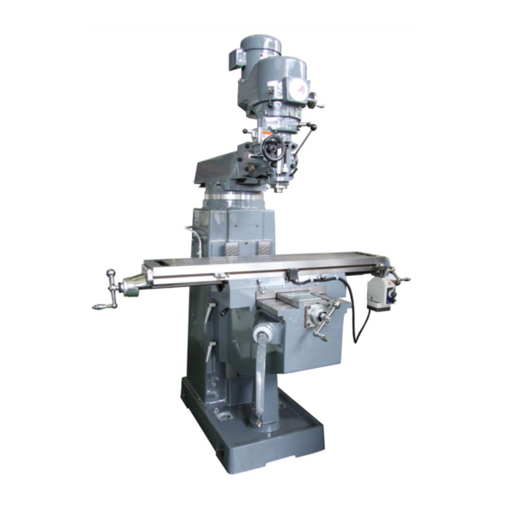
- Page 1 Sharp Precision Machine Tools SERVICE AND PARTS MANUAL Vertical Mill...
- Page 2 SHARP's all new design of 3 HP vari-speed head, just lubricate the van-disc every three months, keep the head running smoothly.
- Page 3 WIRING 440V TO 220V COOLING FANS Warning: Disconnect power source before starting installation. Caution: Follow wiring instruction carefully. For trouble shooting, use a meter to check the current. Do not use the 440V current to check the fan individually. This method of connecting the fans in series to run on 440V current is only applicable to the Twin Fan Model.
- Page 4 After power source has been disconnected, remove the cove, the motor, and make sure that a diagram as shown below is available; if not, please consult a qualified electrician from Sharp Industries Inc. Make proper connection according to the following diagram.
-
Page 5: Table Of Contents
CONTENTS 1. Forward ......................2 2. Safety Rules and Regulations ................2 3. Capacity ......................2 4. Headstock ......................3 (A)195VS ......................3 (a) Name of Machine Parts ............3 (b) Headstock Lubrication .............. 5 (c) Operations ................6 (d) Trouble Shootings ..............10 (B) 195TM ..................... -
Page 6: Forward
1. Forward: LONG CHANG TMV-185 AND TMV-195 OF MILLING MACHINES are designed and manufactured to meet the demands by most of our customers. All parts and materials have been placed under strict quality control to ensure the machine quality superiority and permanent service life. This manual shall give a detailed account of the structure, mechanism, methods of operation, maintenance, etc. -
Page 7: Headstock
4. Headstock (A) Stepless Speed Headstock (195VS) (a) Names of machine parts:... - Page 8 Emergency Stop Speed Meter Forward/Reverse Switch Speed Knob Brake...
-
Page 9: (B) Headstock Lubrication
(b) Headstock lubrication: Adopted with dripping lubricant in the headstock, it is to reassure driving mechanism and smooth sliding. Please refer to the chart as hereunder specified. Item Position Lubricant Time(s) Q’th Headstock matching Quill Holes SHELL TONNA 68 Twice Daily Full... -
Page 10: (C) Operations
(c) Operations: 1. Spindle brake: brake lever (E) When arrow marks in (D) position, spindle motor power is on. When arrow marks in (C) position, spindle motor power off through the engagement of micro switch. When arrow marks in (B) position, make spindle brake. - Page 11 3. Quill feed: a. Manual feed: Turn the feed rate selector to any of the two "DUMMY" positions. Engage feed trip lever from (B) to (B') The quill is now under hand wheel (G) control b. Automatic feed: Ensure quill lock is off (C) Set micrometer dial to required depth, (D) Engage Feed Clutch Selector (E) Select feed rate, (A)
- Page 12 Note: 2. Maximum drilling capacity in automatic feed is 3/4" (19mm). 3. The power feed transmission engagement crank shall be placed at "OUT" position when the automatic feed is not in operation. DO NOT move the power feed transmission engagement crank when the spindle is in revolution. 4.
- Page 13 5 Tilting of headstock Cross tilting (Figure 6) a. Draw out 2 zero position securing taper pins. b. Loosen 4 lock nuts (A) c. Turn the worm shaft (B) so as to tilt the headstock to the desired position. d. Lock up 4 lock nuts (A) evenly.
-
Page 14: (D) Trouble Shootings
6 Headstock Tilting: In-and-Out Tilting (Figure 8): Turn loose evenly the eight adapter locking bolt (P Both sides) and turn the vertical adjusting worm shaft (Q) until the angle desired is obtained. Lock up the bolts (P Both sides) tightly. Note: Do not loosen all the headstock bolts totally. - Page 16 Replacement of speed change belt(R) (Figure 10): Please refer to Step a to e on motor dismantling on P.15. Pull out drawbar (1). Take off three concave hexagonal bolts (1) and use two of them to push up the bearing cover (K).
- Page 18 3 Replacement of brake block (Figure 11, 12): a. Refer to Step a to e on P.14 on motor dismantling. b. Refer to Step b to g on P.13 on replacement of speed change belt to dismantle the upper belt housing.
-
Page 19: (A) Name Of Machine Parts
(B) Headstock (195TM) (a) Names of machine parts:... -
Page 20: (B) Operations
(b) Operation: 1. FINE HAND FEED a. Turn the feed rate selector to any of the two "DUMMY" positions. b. Engage feed trip lever from (B) to (B') c. The quill is now under handwheel (G) control 2. POWER FEED a. - Page 21 4. SPINDLE BRAKE a. When arrow marks in (D) position, spindle motor power is on. b. When arrow marks in (C) position, spindle motor power off through the engagement of micro switch. c. When arrow marks in (B) position, make spindle braked. The lever is cam operated and will never return back until you push it.
-
Page 22: (A) Name Of Machine Parts
5. PARTS REPLACEMENT (a) Names of machine parts: Step speed Headstock:(TMV-185TM) - Page 23 Emergency Stop Speed Meter Forward/Reverse Switch Speed Knob Brake...
-
Page 24: (B) Headstock Lubrication
(b) Headstock Lubrication: 1. TMV-185VS Headstock Item Lubricants Qty. Time Position Head Stock Matching SHELL TONNA 68 Full Twice Daily Quill Holes SHELL TONNA 68 Full Twice Daily Bull Gear Bearing Sleeve Counter Shaft Gear SHELL TONNA 68 Full Twice Daily Worm Gear Cradle... -
Page 25: (C) Operations
(c) Operations: Reversing Switch: Motor turning is controlled by the reversing switch (Vide the Figure in the right). When the high-low speed change lever (Vide P21, 22) is placed at the high gear position and the switch is on FOR, the motor turns clockwise. - Page 26 Cross Tilting Loosen evenly the four lock nuts (R) and turn the worm shaft (S) until the desired angle is secured. Then lock up the lock nuts (R) evenly. Note: 1. Do not loosen the lock nuts (R) totally during the adjustment.
- Page 27 Manual Feed (2) Manual Micromotion Feed: To effectuate the manual micromotion feed, the 1) The manual feed lever is installed on the- power-feed transmission engagement crank (J) right side of headstock (Figure 13, H). The (Fig.13) shall be placed at "OUT" position, and spindle will travel vertically when the lever is feed reverse knob (D) at the neutral position.
- Page 28 5 Automatic Feed: For automatic feeding, please take the following steps (Vide P.21 P22): Loosen the quill lock (L). Turn the power feed transmission engagement crank (j) from "OUT" to "IN" position. 'Make certain to engage the worm gear cradle with the spindle gear hub so that the driving will be directed from the spindle worm and worm gear before it is passed to the speed change gears.
- Page 29 Spindle speed change (a) TMV-185VS By means of the variation of one set of sliding belt pulley and counter shaft gear (high or low speed), the spindle revolution speed is changed accordingly. (1) Change of High and Low Speeds: The speed change may be effectuated by the chosen high and low speed lever (figure 15 (J)). When (J) is engaged in the right front, it is for the high speed and the spindle may rotate as high as 500 to 3,000RPM.
-
Page 30: (D) Trouble Shootings
(d) Trouble Shootings: (A) TMV-185VS Head Stock (1) Dismantling of TMV-185VS Motor (as shown in Figure 17): Start the motor and turn the speed change handvvheel (A) to the position of 60RPM appeared on the indicator to lower down the stationary motor van-disc to the lowest position. Cut off the motor power source and take off wire pressboard and reversing switch. - Page 32 (2) Replacement of Speed Change Belt (as shown in Figure 18): Refer to Step a to e of motor dismantling on P. 31. Take off draw bar (I). Dismantle the three hexagonal concave bolts (j) and use two of them (j) to life the bearing housing (K).
- Page 34 (3) Replacement of Brake Block (Figure 19): a. Refer to Step a to f on P.31 on motor dismantling. Refer to step b to g on P.33 on replacement of speed change belt to dismantle the upper belt housing. As shown in Figure 20, take off the connected gear housing (R) and the four hexagonal concave bolts (V) bottom belt housing (T1).
- Page 35 (4) Replacement of Timing Belt: a. Refer to Step a to e of motor dismantling on P.24. b. Refer to Step b to g speed change belt replacement on P.26 to take off the upper belt housing. c. Refer to Step c to d on P.28 replacement of brake block for the dismantling of bottom belt housing and change the timing belt as shown in Figure 28.
-
Page 36: Machine Body
5. Machine Body (A) Names of machine parts: (a) Column, Turret and Ram: (185 TM/VS) - Page 37 (b) Column, Turret and Ram: (195 TM/VS)
- Page 38 (c) Work Table, Saddle and Knee:( TMV-185/LC -19 5)
-
Page 39: (B) Machine Lubrication
(B) Machine lubrication Lubrication of work table, saddle, knee, sliding surface and leadscrews may be Position effectuated by means of the hand crank pump on the left side of knee. Method 3 to 5 times daily by pulling twice each time. Lubricant SHELL TONNA 68... -
Page 40: (C) Operations
(C) Operations: (a) Ram Movement and Swiveling: Movement: Loosen the two Ram lock levers (A). Swivel the Ram pinion handle (B), and the Ram can be moved. When it moves to the desired position, lock up (A). Ram Swiveling: Loosen the four locking bolts (C), and force the cross arm to turn until the desired angle is obtained. - Page 41 (b) Zero Positioning (as shown in Figure 23) of Dial Ring of Table Feed. 1. Loosen the nut (D) of dial ring. 2. Turn the dial right (E) to zero position. 3. Lock the nut (D) of dial ring. (c) Setting of Sliding Surfaces of Work Table, Saddle and Knee: All non-feed sliding Surfaces shall be secured and set to prevent slipping and increase machine body's rigidity.
-
Page 42: (D) Adjustment
(D) Adjustment: (a) Adjustment of Backlash of Leadscrew: After a certain period of time, a clearance is developed between the leadscrew and its nut due to frictions. Positioning accuracy will become impossible. Therefore, the nut must be adjusted so as to keep a proper tension between itself and the leadscrew. 1. - Page 43 2. Adjustment of Backlash of Longitudinal Leadscrew: Move the work table to the center of saddle. Insert the large end of backlash adjustment tool into the left side of saddle. Turn the locking nut (J) counterclockwise one round. Reverse the end of adjustment tool and insert the small end into same position and turn the leadscrew adjusting nut (K) clockwise.
- Page 44 3. Adjustment of Work Table Gib (Figure 27): Work table gib (C) is attached between saddle and work table dovetail. Loosen the setting lever (A) (Vide Figure 27). Clean the slideway and add the lubricant Use a screwdriver to adjust the big bolts (B) on left and right sides of the saddle. Method of Adjustment.
- Page 45 4. Adjustment of Saddle Gib (Figure 28): Saddle gib is attached to the position between the left side of saddle and the knee. Loosen the saddle lock lever (A) (Vide Figure 28). Move the saddle to the front part of the knee. Take off the front and rear wiper holders (B) of saddles.
- Page 46 5. Adjustment of Knee Glb on Machine Body (Vide Figure 29): Knee gib is attached to the position between the side of knee and the column slideway. a. Loosen the lock bolt (A) by using hexagonal spanner. b. Take off the wiper holder (B). Clean the slideway and add the lubricant.
- Page 47 6. Adjustment of Ram Gib (Vide Figure 30): Ram gib is attached to the position between the ram and the turret dovetail. Tightness of ram can be adjusted properly by gib bolts. a. Loosen the ram lock bolts (A). b. Clean the slideway and add the lubricant c.
-
Page 48: Maintenance
6. Maintenance: "Maintenance is more important than repair, shall be moved to the proper position. and repair is better than purchase". Then cutter must be dismantled. (6) At the close of each day, the headstock Under long-term operations, if the machine has must be restored to its normal position if not been properly maintained and operated, its it is tilted. - Page 49 TROUBLE CAUSE CORRECTION SPINDLE POWER FEED The two M4 set screws on disengage lever DISENGAGEMENT NOT Tighten set screws loosed WORK WELL 1. Power feed rates selecting knob set on Rotate this knob to one of HAND MICRO-FEED NOT one of the three feed the two "DUMMY"...
- Page 50 1. Peripheral relief too great. 1. Use recommended angle. CUTTING "HOGSIN" 2. Rake, angle too large 2. Decrease rake angle. 3. Improper speed 3. Check and adjust. 1. Use recommended clearance angle 1. Insufficient clearance rubbing VIBRATION 2. Check machine, be sure 2.
-
Page 51: Chart Of Feed And Cutting Speed
7. Cutting Condition Chart FEED- (in mm) PER TOOTH FOR HIGH SPEED STEEL AND HARD METAL CUTTERS, MILLING IN CONVENTIONAL FEED DIRECTION FORM TIPPED CUTTER HEADS PLAIN FACE ULTIMATE SLOTTING RELIEVED SLITTING WORKPIECE HARDNESS MILLING MILLING END MILLS HIGH SPEEED HARD STRENGTH CUTTERS... - Page 52 CUTTING SPEEDS (IN m/min.) OF HIGH SPEED STEEL AND METAL CUTTERS, MILLING IN CONVENTIONAL FEED DIRECTION FORM TIPPED CUTTER HEADS PLAIN FACE ULTIMATE SLOTTING RELIEVED SLITTING WORKPIECE HARDNESS MILLING MILLING END MILLS HIGH SPEEED HARD STRENGTH CUTTERS PROFILE SAWS CUTTERS CUTTERS STEEL METAL...
-
Page 54: Cautions
8. Cautions (1) Machine Operations: (2) Machine operator: Check and ensure if the machine bottom The machine is to be started or operated and ground base are properly contacted by an authorized operator only. before the anchor bolts are locked up. Immediate stop and repair are needed in The machine must be installed upon a case of troubles in operations. -
Page 55: Remarks
PARTS LIST... - Page 56 Inverter Head Controls Emergency Forward/Neutral/Reverse Control Speed Control RPM Indicator...
- Page 57 DVS HEAD PARTS 1 PART NUMBER DESCRIPTION QUANTITY H-014 SHIFT CRANK H-097 GEARSHIFT PLUNGER H-262 COMPRESSION SPRING H-284 BLACK PLASTIC BALL H-502 GEAR HOUSING H-504 BELT HOUSING (BOTTOM) H-505 BELT HOUSING (UPPER) H-727 RPM DISPLAY HOUSING H-728 SWITCH HOUSING H-729 HOUSING PLATE E-22S38B-EVS FORWARD REVERSE...
- Page 58 DVS HEAD PARTS 1...
- Page 59 DVS HEAD PARTS 2 PART NUMBER DESCRIPTION QUANTITY H-149 DRAW BAR WASHER H-250 SOCKET SET SCREW 1/2” x 5/16” H-290 BEARING LOCK NUT H-291 LOCK WASHER H-505 BELT HOUSING (UPPER) H-515 TOP BEARING CAP H-516 WAVE WASHER H-517 BALL BEARING 6007ZZ H-522 BALL BEARING...
- Page 60 DVS HEAD PARTS 2...
- Page 61 DVS Parameters Initial Setting Current Setting Initial Setting Current Setting 102.0 1.03...
- Page 63 PARTS NO. DESCRIPTION REMARKS VH-H594 PIVOT SLEEVE VH-H596 SPEED CHANGE PLATE VH-H607 WORM GEAR SHAFT SUPPORTER VH-H613 SPEED CHANGE HOUSING VH-H616 WORM VH-H617 SPEED CONTROL SHAFT VH-H621 BRONZE BEARING VH-H622 SPEED CHANGE HAND WHEEL VH-H623 SPEED CHANGE WARING PLATE VH-H624 HANDLE VH-H666 DRAWBAR...
- Page 64 PARTS NO. DESCRIPTION REMARKS TM-H001 QUILL HOUSING TM-H002 GEAR HOUSING TM-H003 GEAR HOUSING COVER TM-H004 BELT HOUSING TM-H005 SPINDLE PULLEY TM-H006 MOTOR PULLEY TM-H007 TIMING BELT PULLEY TM-H008 TIMING BELT PULLEY FLANGE TM-H012 BACK GEAR SHIFTER FORK TM-H013 SPINDLE PULLEY BEARING SLEEVE TM-H019 MOTOR PULLEY WASHER TM-H030...
- Page 65 PARTS NO. DESCRIPTION REMARKS TM-H131 MOTOR LOCK NUT TM-H132 MOTOR LOCK NUT HANDLE TM-H133 MOTOR MOUNTING STUDS TM-H134 MOTOR MOUNTING STUDS WASHER TM-H149 DRAWBAR WASHER (R8) TM-H150 SOCKET SET SCREW TM-H157 QUILL MICRO STOP NUT (IN) TM-H165 SPINDLE (NT30) TM-H166 SPINDLE (R8) TM-H167 QUILL (R8 NT30)
- Page 66 PARTS NO. DESCRIPTION REMARKS 18VH-H090 QUILL (NT40) 18VH-H094 DRAWBAR KNOW NUT (NT40) 18VH-H096 DRAWBAR (NT40) 18VH-H097 DRAWBAR (NT40) FILE NAME: TM-03...
- Page 68 PARTS NO. DESCRIPTION REMARKS TM-H004 BELT HOUSING TM-H013 SPINDLE PULLEY BEARING SLEEVE TM-H084 CAM RING TM-H086 SPINDLE CLUTCH CAM RING PIN TM-H087 BRAKE BLOCK TM-H088 BRAKE RING SCREW TM-H089 BRAKE LOCK STUD TM-H091 BRAKE LOCK WASHER TM-H092 BRAKE LOCK HANDLE TM-H093 BRAKE LOCK PIN TM-H284...
- Page 70 PARTS NO. DESCRIPTION REMARKS TM-H002 GEAR HOUSING TM-H003 GEAR HOUSING COVER TM-H004 BELT HOUSING TM-H012 BLACK GEAR SHIFTER FORK TM-H014 SHIFT CRANK TM-H095 COUNTER SHAFT TM-H096 COUNTER SHAFT GEAR TM-H097 GEAR SHAFT PLUNGER TM-H152 BACK GEAR SHAFT BUSHING TM-H153 BACK GEAR SHAFT CRANK TM-H284 BLACK PLASTIC BALL TM-H334...
- Page 71 PARTS NO. DESCRIPTION REMARKS TM-H001 QUILL LOCK SLEEVE TM-H010 QUILL LOCK SLEEVE TM-H011 QUILL LOCK BOLT TM-H014 WORM GEAR TM-H015 WORM SHAFT TM-H016 SOCKET SET SCREW TM-H017 GEAR FILE NAME: TM/VS-08...
- Page 73 PARTS NO. DESCRIPTION REMARKS TM-H001 QUILL HOUSING TM-H008 TIMING BELT PUULEY FLANGE TM-H035 QUILL SKIRT TM-H036 QUILL STOP KNOB TM-H037 QUILL STOP MICRO SCREW (IN) TM-H038 MICROMETER NUT (IN) TM-H071 VERTICAL TEE BOLT WASHER TM-H126 FEED DRIVE WORM GEAR TM-H149 DRAWER WASHER (R8) TM-H150 SOCKET SET SCREW...
- Page 74 PARTS NO. DESCRIPTION REMARKS VH-H503 GEAR HOUSING PLATE VH-H504 BELT HOUSING (BOTTOM) VH-H505 BELT HOUSING (UP) VH-H056 STUDS VH-H057 GEAR HOUSING VH-H515 TOP BEARING CAP VH-H520 VH-H521 ADJ DRIVEN BARI-DISC ASSEMBLY VH-H523 SLIDING HOUSING VH-H525 STATIONARY DRIVEN VARI-DISC VH-H526 STATIONARY MOTOR VARI-DISC VH-H531 SLIDING KEY VH-H533...
- Page 75 PARTS NO. DESCRIPTION REMARKS VH-H589 GEAR HOUSING PLATE VH-H596 BELT HOUSING (BOTTOM) VH-H597 BELT HOUSING (UP) VH-H099 STUDS VH-H601 GEAR HOUSING VH-H602 TOP BEARING CAP VH-H605 VH-H607 ADJ DRIVEN BARI-DISC ASSEMBLY VH-H609 SLIDING HOUSING VH-H610 STATIONARY DRIVEN VARI-DISC VH-H611 STATIONARY MOTOR VARI-DISC VH-H613 SLIDING KEY VH-H614...
- Page 77 PARTS NO. DESCRIPTION REMARKS VH-H503 GEAR HOUSING PLATE VH-H504 BELT HOUSING (BOTTOM) VH-H505 BELT HOUSING (UP) VH-H507 GEAR HOUSING VH-H510 OIL PLUG VH-H515 TOP BEARING CAP VH-H521 ADJ DRIVEN BARI-DISC ASSEMBLY VH-H523 SLIDING HOUSING VH-H525 STATIONARY DRIVEN VARI-DISC VH-H541 DRAWBAR (R8 6/17” x 20UNF) VH-H542 DRAWBAR (NT30 1/2”...
- Page 79 PARTS NO. DESCRIPTION REMARKS TM-C222 UPPER WORM SPACER 18VS-C002 TM-C225 RAM ADAPTER TM-C226 VERTICAL ADJUSTING WORM TM-C227 VERTICAL ADJUSTING WORM SHAFT TM-C232 WORM THRUST WASHER TM-C007 TURRET TM-H144 GEAR FILE NAME: 195-01 (TM/VS HEAD)
- Page 81 PARTS NO. DESCRIPTION REMARKS 18VH-C021 OVERARM-TURRET GIB 195-C007 TURRET 18VH-C023 GIB STATIONARY BOLT 18VH-C025 OVERARM LOCK PLUNGER 18VH-C026 OVERARM LOCK BOLT 18VH-C028 PINION BUSHING TM-C473 T-BOLT TM-H091 BRAKE LOCK WASHER 18VH-C178 OVERARM RACK TM-C219 HEAD ROTATION STOP PIN TM-C228 ADAPTER PIVOT STUD TM-C236 SCALE TM-C225...
- Page 83 PARTS NO. DESCRIPTION REMARKS 18VH-C021 OVERARM-TURRET GIB 195-C007 TURRET 18VH-C023 GIB STATIONARY BOLT 18VH-C025 OVERARM LOCK PLUNGER 18VH-C026 OVERARM LOCK BOLT 18VH-C028 PINION BUSHING 18VH-C034 T-BOLT 18VH-C035 FALT WASHER 18VH-C178 OVERARM RACK 18VH-C247 HEAD ROTATION STOP PIN 18VH-C249 ADAPTER PIVOT STUD 18VH-C250 SCALE 18VH-C251...
- Page 85 PARTS NO. DESCRIPTION REMARKS 18VS-H274 T-BOLT 18VS-C COVER 18VS-C OVERARM 18VS-C SCALE 18VH-C OVERARM-TURRET GIB 195-C007 TURRET 18VH-C GIB STATIONARY BOLT 18VH-C OVERARM LOCK PLUNGER 18VH-C OVERARM LOCK BOLT 18VH-C PINION BUSHING 18VH-C OVERARM MOVING RACK 2G-C016 OVERARM MOVING PINION 18VS-H QUILL HOUSING TM-H144...
- Page 87 PARTS NO. DESCRIPTION REMARKS TM-C069 DIAL LOCK NUT TM-C074 DIAL HOLDER TM-C338 DIAL WITH 200 GRADUATION TM-C079 DIAL HOLDER TM-C080 HAND WHEEL TM-C108 LOCK SCREW TM-C109 SCREW ADJUSTING NUT TM-C110 FEED NUT BRACKET TM-C340 LONGITUDINAL FEED NUT TM-C115 LEFT BEARING BRACKET TM-C117 BEARING SPACER TM-C118...
- Page 89 PARTS NO. DESCRIPTION REMARKS TM-C121 TABLE LOCK BOLT TM-C122 TABLE LOCK BOLT HANDLE TM-C123 TABLE STOP BRACKET TM-C125 TABLE STOP PIECE TM-C126 STOP PIECE T-BOLT TM-C230 RAM LOCK BOLT 185-C002 KNEE 185-C006 SADDLE 185-C008 TABLE 185-C009 SADDLE KNEE GIB 185-C014 SADDLE KNEE WIPER 185-C025 SADDLE KNEE GIB...
- Page 91 PARTS NO. DESCRIPTION REMARKS TM-C334 ELEVATING SCREW HOUSING TM-C057 WASHER TM-C059 BEVEL GEAR TM-C069 DIAL LOCK NUT TM-C074 DIAL HOLDER TM-C077 CROSS FEED BEARING BRACKET TM-C338 DIAL WITH 200 GRADUATIONS TM-C080 HAND WHEEL TM-C339 CROSS FEED NUT TM-C108 LOCK SCREW TM-C109 SCREW ADJUSTING NUT TM-C110...
- Page 93 PARTS NO. DESCRIPTION REMARKS TM-C028 HANDLE TM-C057 WASHER TM-C059 BEVEL GEAR TM-C060 BEVEL PINION TM-C064 BEARING CUP TM-C065 BEARING RETAINING RING TM-C038 DIAL HOLDER TM-C069 DIAL LOCK NUT TM-C070 GEAR SHAFT CLUTCH INSERT TM-C071 ELEVATING CRANK TM-C336 DIAL WITH 100 GRADUATIONS 195-C032 GEAR SHAFT FOR KNEE 195-C010...
- Page 95 PARTS NO. DESCRIPTION REMARKS VH-H515 BEARING HOUSING VH-H520 SLIDING KEY VH-H521 ADJ DRIVEN VARI-DISC VH-H523 BEARING BRACKET VH-H526 MOTOR STATIONARY VARI-DISC VH-H528 MOTOR VH-H531 SLIDING KEY VH-H533 ADJ MOTOR VARI-DISC VH-H534 SPRING VH-H535 SPRING-WASHER VH-H539 BOTTOM BEARING CAP VH-H596 SPEED CHANGE PLATE VH-H597 SPEED CHANGE PLATE PIVOT STUD VH-H601...
- Page 96 PARTS NO. DESCRIPTION REMARKS 18VS-H028 SPINDLE CLUTCH 18VS-H032 SPEED CHANGE GEAR 18VS-H034 SPEED CHANGE GEAR SHAFT 18VS-H036 BACK GEAR 18VS-H041 BEARING BRACKET 18VS-H045 BEARING SPACER 18VS-H163 QUILL STOP KNOB 18VS-H188 BRAKE SHOE 18VS-H210 SPINDLE PULLEY HUB 18VS-H211 SPACER 18VS-H212 STATIONARY DRIVEN VARI-DISC 18VS-H230 BELT HOUSING 18VS-H233...
- Page 100 PARTS NO. DESCRIPTION REMARKS 18VS-H001E QUILL HOUSING -H090 DOWN FEED WORM -H093 BEARING SPACER -H103B BEARING PLUNGER -H104B BEARING PLUNGER -H106A DIAL SCREW -H295B PLATE 2GH-033 GRIP -169 UP FEED WORM GEAR -171 SPEED CHANGE GEAR CLUSTER SHAFT -173 SPEED CHANGE CLUSTER -177 BEARING SPACER -178...
- Page 102 PARTS NO. DESCRIPTION REMARKS 18VS-H001E QUILL HOUSING -H041B BEARING BRACKET -H186A BRAKE LOCK STUD -H188 BRAKE SHOE -H190B LIMIT SWITCH HOLDER -H193A SHIFTER PLATE -H230B BELT HOUSING -H255B SPEED CHANGE HOUSING -H266A HI-LOW SPEED PLATE -H267A WORM SHAFT SLEEVE -H268 SPEED CHANGE WORM SHAFT -H270A SPEED CHANGE HANDWHEEL...
- Page 104 PARTS NO. DESCRIPTION REMARKS 18VH-C022 TURRET 18VH-C029 TURRET ROTARY RING 18VH-C248 WORM SHAFT 18VH-C251 RAM ADAPTER 18VH-C252 OVERARM TM-H144 HORIZONTAL ADJUSTING WORM TM-C222 WORM SPACER TM-C226 VERTICAL ADJUSTING WORM TM-C232 WORM THRUST WASHER A-27 C-18...