
Related Manuals for Motorola ASTRO 25 GTR 8000


Summary of Contents for Motorola ASTRO 25 GTR 8000
- Page 1 ® ASTRO INTEGRATED VOICE AND DATA GTR 8000 Base Radio FEBRUARY 2020 MN003286A01-E © 2020 Motorola Solutions, Inc. All rights reserved...
-
Page 2: Declaration Of Conformity
This device must accept any interference received, including interference that may cause unde- sired operation. • Changes or modifications made to this device, not expressly approved by Motorola Solutions, could void the authority of the user to operate this equipment. -
Page 3: Copyrights
Motorola Solutions, Inc. Furthermore, the purchase of Motorola Solutions products shall not be deemed to grant either directly or by implication, estoppel or otherwise, any license under the copyrights, patents or patent applications of Motorola Solutions, except for the normal non-exclusive, royalty-free license to use that arises by operation of law in the sale of a product. -
Page 4: Contact Us
Your organization received support phone numbers and other contact information appropriate for your geographic region and service agreement. Use that contact information for the most efficient response. However, if needed, you can also find general support contact information on the Motorola Solutions website, by following these steps: 1 Enter motorolasolutions.com... -
Page 5: Document History
MN003286A01-E Document History Document History Version Description Date MN003286A01-A Original release of the GTR 8000 Base Radio November 2016 manual MN003286A01-B Updated the following sections: November 2016 • CSS Initial Device Configuration on page 134 • GTR 8000 Base Radio General Troubleshoot- ing on page 212 MN003286A010-C Updated the following sections:... - Page 6 MN003286A01-E Document History Version Description Date MHz) on page 45 – GTR 8000 Base Radio FCC Identification for IV&D UHF R1 (380–435 MHz) • GTR 8000 Base Radio Industry Canada for In- tegrated Voice and Data UHF R1 (380–435 MHz) on page 48 •...
-
Page 7: Table Of Contents
MN003286A01-E Contents Contents Declaration of Conformity..................2 Copyrights........................3 Contact Us........................4 Document History....................... 5 List of Figures......................16 List of Tables......................20 List of Processes...................... 23 List of Procedures.....................24 About GTR 8000 Base Radio..................27 What Is Covered In This Manual?....................27 Helpful Background Information.................... - Page 8 MN003286A01-E Contents 1.12.2.1 GTR 8000 Base Radio Industry Canada for Integrated Voice and Data UHF R1 (380–435 MHz)................48 1.12.3 GTR 8000 Base Radio Specifications for Integrated Voice and Data UHF R2 (435–524 MHz) ......................49 1.12.3.1 GTR 8000 Base Radio Industry Canada for Integrated Voice and Data UHF R2 (435–524 MHz)................52 1.12.4 GTR 8000 Base Radio Specifications for Integrated Voice and Data VHF (136–174 MHz) ......................
- Page 9 MN003286A01-E Contents 2.3.10 RFDS - External Dual Circulator/Isolator Tray (VHF)..........76 2.3.11 Antenna Relay Module...................76 2.3.11.1 Mounting Locations.................. 77 2.3.11.2 Functional Operation................79 Chapter 3: GTR 8000 Base Radio Installation............82 3.1 Pre-Installation Tasks......................82 3.1.1 Equipment Installation Process Overview..............82 3.2 General Safety Precautions....................83 3.2.1 GTR 8000 Base Radio Supplemental Safety Installation Requirements....
- Page 10 MN003286A01-E Contents 3.4.2.1 Floor Mounting the Cabinet Version of the GTR 8000 Base Radio... 95 3.4.2.2 Physical Dimensions and Clearances of the Cabinet Version of the GTR 8000 Base Radio..................96 3.4.2.3 Cabinet Mounting Rails................97 3.4.2.4 Vertical Lifting of Cabinets................. 97 3.4.2.5 Removing/Replacing a Cabinet Door............98 3.4.3 Rack Mounting The GTR 8000 Base Radio............100 3.4.3.1 Mounting the GTR 8000 Base Radio............
- Page 11 MN003286A01-E Contents 4.2 Discovering a Device in the UNC..................132 4.3 Security/Authentication Services..................133 4.4 Device Configuration in CSS....................134 4.4.1 CSS Initial Device Configuration................134 4.4.2 Connecting Through a Serial Port Link..............135 4.4.3 Serial Connection Configurations................137 4.4.3.1 Setting the Device IP Address and Pairing Number in CSS....137 4.4.3.2 Pairing To a Comparator................137 4.4.3.3 Serial Security Services in CSS...............
- Page 12 MN003286A01-E Contents 5.9 Tuning a Preselector......................159 5.9.1 VHF Tuning Procedures..................160 5.9.1.1 Calculating Proper VHF Alignment Frequency........160 5.9.1.2 Preparing the Equipment for VHF Alignment........... 161 5.9.1.3 Tuning The VHF Preselector..............161 5.9.2 UHF Tuning Procedures..................162 5.9.2.1 Calculating Proper UHF Alignment Frequency........163 5.9.2.2 Preparing the Equipment for UHF Alignment...........164 5.9.2.3 Tuning The UHF Preselector..............
- Page 13 8.4 Conventional Site Controller Failure - Impact on GTR 8000 Base Radio for Conventional Operation......................219 8.5 Motorola Solutions Support Center..................219 8.5.1 Information Necessary to Contact Motorola Solutions Support Center....219 8.5.2 Where to Call for Service..................220 8.5.2.1 Motorola Solutions Support Center............220...
- Page 14 MN003286A01-E Contents 8.5.3 Subcontractors.......................221 Chapter 9: GTR 8000 Base Radio FRU Procedures..........222 9.1 Field Replaceable Units (FRUs) and Parts................222 9.2 Transceiver Hardware Generations..................226 9.2.1 Transceiver Software and Feature Compatibilities..........226 9.2.2 Identifying Transceiver Hardware Generation............227 9.2.3 Transceiver FRU Number Mappings..............228 9.3 Power Amplifier Hardware Generations................
- Page 15 MN003286A01-E Contents 10.2.4 Preselector Filter Specifications (VHF)..............271 10.2.5 Duplexer Specifications (700/800 MHz)...............272 10.2.6 Duplexer Specifications (UHF)................272 10.2.7 Duplexer Specifications (VHF)................273 10.2.8 External Dual Circulator Specifications (700/800 MHz)........273 10.2.9 External Dual Circulator Specifications (UHF)............. 274 10.2.10 External Dual Circulator Specifications (VHF)........... 274 10.2.11 Antenna Relay Specifications................
-
Page 16: List Of Figures
MN003286A01-E List of Figures List of Figures Figure 1: GTR 8000 Base Radio......................29 Figure 2: Single-Site Repeater Configuration 1..................33 Figure 3: Single Site Repeater Configuration 2..................33 Figure 4: GTR 8000 Base Radios in HPD Remote Site................. 35 Figure 5: Transceiver Module (Front View).................... 61 Figure 6: Transceiver Control Board Information Flow................62 Figure 7: Transceiver RESET Switch (viewable through the drop-down door)........ - Page 17 MN003286A01-E List of Figures Figure 36: Cabinet Door Removal......................99 Figure 37: Cabinet Door Replacement....................99 Figure 38: Base Radio Mounted in Rack .....................100 Figure 39: Battery Temperature Sensor Example 1................103 Figure 40: Battery Temperature Sensor Example 2................104 Figure 41: Rack Grounding........................
- Page 18 MN003286A01-E List of Figures Figure 75: Verifying UHF Duplexer Insertion Loss — Connecting Test Equipment......181 Figure 76: Verify UHF Duplexer Insertion Loss — Connecting Duplexer Cable Assembly....181 Figure 77: Verifying UHF Duplexer Isolation — Connecting Test Equipment........182 Figure 78: Verifying UHF Duplexer Isolation — Connecting Duplexer Cable Assembly ..... 183 Figure 79: Metering Screen Window....................
- Page 19 MN003286A01-E List of Figures Figure 110: External Dual Circulator/Isolator Tray (700/800 MHz)............254 Figure 111: External Dual Circulator/Isolator Tray (UHF)..............255 Figure 112: Duplexer Module (700/800 MHz)..................258 Figure 113: Duplexer Module (UHF)....................259 Figure 114: Duplexer Module for IVD (VHF)..................261 Figure 115: Transceiver LEDs (viewable through a drop-down door)..........
-
Page 20: List Of Tables
MN003286A01-E List of Tables List of Tables Table 1: Base Radio Modules and Function...................30 Table 2: Standby Power Consumption....................39 Table 3: GTR 8000 Base Radio General Specifications IV&D (700/800 MHz) ........40 Table 4: GTR 8000 Base Radio Transmitter Specifications for IV&D (700/800 MHz) ......42 Table 5: GTR 8000 Base Radio Specifications for IV&D (700/800 MHz) ..........43 Table 6: GTR 8000 Base Radio FCC Identification for IV&D (700/800 MHz) ........ - Page 21 MN003286A01-E List of Tables Table 37: Base Radio Backplane Connections for HPD..............109 Table 38: Transceiver Connections - Front..................111 Table 39: 50–Pin System Connector Pin-Outs (Conventional)............112 Table 40: 50–Pin System Connector Pin-Outs (Trunked 3600)............115 Table 41: Wireline Port Pin-Outs......................117 Table 42: Microphone Port Pin-Outs....................
- Page 22 MN003286A01-E List of Tables Table 76: External Dual Circulator Specifications (VHF)..............274 Table 77: Antenna Relay Specifications....................275 Table 78: T2-2R Receiver Mute Option Kit Parts List................282 Table 79: T3-3R Receiver Mute Option Kit Parts List................284 Table 80: T4-4R Receiver Mute Option Kit Parts List................287 Table 81: Total Transmit and Receive Attenuation for T2-2R, T3-3R, and T4-4R Receiver Mute..
-
Page 23: List Of Processes
MN003286A01-E List of Processes List of Processes Equipment Installation Process Overview ..................... 82 Installing Device Software Prerequisites ..................... 121 Installing Devices in the UNC ......................124 Discovering a Device in the UNC ......................132 CSS Initial Device Configuration ......................134 Setting CSS Configuration Parameters for the GTR 8000 Base Radio (Trunked Simulcast) ..... -
Page 24: List Of Procedures
MN003286A01-E List of Procedures List of Procedures Configuring The Ethernet LAN Switch ....................34 Mounting Cabinets or Racks to a Floor ....................88 Lifting Cabinets Vertically ........................97 Removing/Replacing a Cabinet Door ....................98 Mounting the GTR 8000 Base Radio ....................100 Grounding the GTR 8000 Base Radio ....................105 Discovering a Device in the UNC ...................... - Page 25 MN003286A01-E List of Procedures Tuning VHF Duplexer Low Pass Resonators ..................168 Tuning VHF Duplexer High Pass Resonators ..................169 Tuning VHF Duplexer High Notch Loop Assemblies ................170 Tuning VHF Duplexer Low Notch Loop Assemblies ................171 Verifying VHF Duplexer Insertion Loss ....................173 Verifying VHF Duplexer Isolation ......................175 Checking VHF Duplexer After Tuning ....................
- Page 26 MN003286A01-E List of Procedures Replacing a Duplexer (VHF) ........................261 Replacing an Antenna Relay ....................... 262 Performing a Site Download With PSC 9600 Site Controllers .............276 Performing a Site Software Download With GCP 8000 Site Controllers ..........278 Installing the T2-2R, T3-3R, and T4-4R Receiver Mute Option Kits ............291 Configuring the T2-2R, T3-3R, and T4-4R Receiver Mute Option Kits ..........
-
Page 27: About Gtr 8000 Base Radio
GTR 8000 Base Radio. Helpful Background Information Motorola Solutions offers various courses designed to assist in learning about the system. For information, go to http://www.motorolasolutions.com/training to view the current course offerings and... -
Page 28: Related Information
Standards and Guidelines for Communi- Provides standards and guidelines that should be followed when cation Sites setting up a Motorola Solutions communications site. This may be purchased on CD 9880384V83, by calling the North America Parts Organization at 800–422–4210 or the international number at 302–444–9842. -
Page 29: Chapter 1: Gtr 8000 Base Radio Description
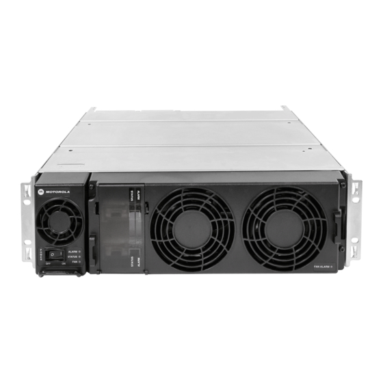
MN003286A01-E GTR 8000 Base Radio Description Chapter 1 GTR 8000 Base Radio Description This chapter provides a high-level description of the GTR 8000 Base Radio and the function it serves in your system. Introduction Figure 1: GTR 8000 Base Radio This manual provides information on the standalone GTR 8000 Base Radio and associated applications. -
Page 30: Gtr 8000 Base Radio Components
MN003286A01-E Chapter 1: GTR 8000 Base Radio Description GTR 8000 Base Radio Components Table 1: Base Radio Modules and Function Base Radio Description Power Supply Operates from either an AC or DC input and provides the DC operating voltage for the base radio. May also provide a separate battery charger to maintain the charge on a 48 VDC nominal system, positive or negative ground. -
Page 31: Supported Frequencies For Trunked Iv And D And Conventional Architectures
• VHF (136–174 MHz) NOTICE: RF Distribution Functionality (RFDS) information provided in this documentation pertains to the RFDS equipment supplied by Motorola Solutions. 1.3.2 Supported Frequencies for HPD The GTR 8000 Base Radio is available for 25 kHz operation in the following frequency bands: •... -
Page 32: Overview For A Gtr 8000 Base Radio In A Trunked Single-Site Repeater Configuration
MN003286A01-E Chapter 1: GTR 8000 Base Radio Description A maximum of 28 base radios can be installed at the site. Each base radio has either an Ethernet connection to a site LAN switch or an Ethernet connection to both site controllers at the site, depending on the site configuration. -
Page 33: Figure 2: Single-Site Repeater Configuration 1
MN003286A01-E Chapter 1: GTR 8000 Base Radio Description Figure 2: Single-Site Repeater Configuration 1 If the distance between the first non-colocated base radio and subsequent non-colocated base radios is less than 328 ft (100 m), a single Ethernet LAN switch can be used to distribute the site controllers call control signaling to those non-colocated base radios. -
Page 34: Configuring The Ethernet Lan Switch
MN003286A01-E Chapter 1: GTR 8000 Base Radio Description Each non-colocated base radio is equipped with a transceiver option card, which provides an internal 10 MHz frequency reference. See the “Reference Oscillator Alignment Procedures” of the base radio Alignment Screens in the Configuration/Service Software (CSS) Online Help for alignment details. The base radios that are colocated with the site controllers do not require the transceiver option card. -
Page 35: Overview For A Gtr 8000 Base Radio In Conventional Architectures
MN003286A01-E Chapter 1: GTR 8000 Base Radio Description The HPD base radio provides a full-duplex RF interface to HPD Mobile Subscriber Units (MSUs). The HPD base radios are available for 25 kHz HPD operation in the 700 MHz or 800 MHz bands. Up to five HPD base radios may be installed at the site. -
Page 36: Astro 25 Conventional Base Radio
MN003286A01-E Chapter 1: GTR 8000 Base Radio Description • A Centralized or Distributed Conventional Architecture, or ® • An ASTRO 3.1 Conventional System. Each conventional base radio uses either: • A 2- or 4-wire TRC or 4-wire E&M interface in an analog infrastructure •... -
Page 37: Analog Conventional Base Radio
MN003286A01-E Chapter 1: GTR 8000 Base Radio Description • ASTRO ® 3.1 Conventional Systems • Centralized Conventional Architectures Zone Core with Colocated Conventional Channels Trunked IP Simulcast Remote Site with Conventional Channels Dispatch Console Site with Colocated Conventional Channels Conventional-Only Remote Site HPD Site with Conventional Channels •... -
Page 38: Overview Of A Gtr 8000 Base Radio In A Trunked 3600 System
MN003286A01-E Chapter 1: GTR 8000 Base Radio Description • Simulcast • Console Control Monitor Mode Repeat Control Frequency Select * For detailed information on the differences between the automatic Fallback In-Cabinet Repeat and the externally wired In-Cabinet Repeat functions, see the Conventional Operations manual. An analog conventional base radio can be used in the following architectures: •... -
Page 39: License Auditing
MN003286A01-E Chapter 1: GTR 8000 Base Radio Description The Power Efficiency Package hardware includes a modified transceiver, power amplifier, power supply, fan, and optional transceiver option card (internal reference) along with additional software configurations through Configuration/Service Software (CSS). The following conditions must be met to obtain a power consumption of less than or equal to 35 W: •... -
Page 40: Gtr 8000 Base Radio Specifications
MN003286A01-E Chapter 1: GTR 8000 Base Radio Description • Vote audio • Implement site control functions; such as assigning channels or calls. Any issues with an existing site license are sent to the UEM without system functionality being restricted. 1.12 GTR 8000 Base Radio Specifications The following G-Series Product Specifications... - Page 41 MN003286A01-E Chapter 1: GTR 8000 Base Radio Description General Specifications Above 3000 meters (9800 ft), the peak power derating for the Tx filter is 1 dB/1km (0.3 dB/ 1000 ft) Maximum operational altitude is 5000 meters (16900 ft) Power Requirements AC: 90-264 VAC, 47-63 Hz DC: 43.2-60 VDC Power Consumption Transmitting –...
-
Page 42: Table 4: Gtr 8000 Base Radio Transmitter Specifications For Iv&D (700/800 Mhz)
MN003286A01-E Chapter 1: GTR 8000 Base Radio Description General Specifications Frequency Generation Synthesized Table 4: GTR 8000 Base Radio Transmitter Specifications for IV&D (700/800 MHz) Transmitter Specifications Frequency Range 769-775, 775-776, 851–870 MHz Power Output* (Low-Power, 700/800 MHz) 2-30 W Power Output* (Mid-Power, 700/800 MHz) 2-100 W Power Output* (High-Power, 800 MHz) -
Page 43: Table 5: Gtr 8000 Base Radio Specifications For Iv&D (700/800 Mhz)
MN003286A01-E Chapter 1: GTR 8000 Base Radio Description Transmitter Specifications Intermodulation Attenuation (High-Power, 800 55 dB MHz) Intermodulation Attenuation (Mid-Power, 80 dB 700/800 MHz) *Full transmitter output power is available during battery revert. NOTICE: The output power reference plane is the output connector of the power amplifier. The loss of the transmitter output cable (PA output to back of base radio) is 4% at 800 MHz. -
Page 44: Gtr 8000 Base Radio Industry Canada For Integrated Voice And Date (700/800 Mhz)
MN003286A01-E Chapter 1: GTR 8000 Base Radio Description Receiver Specifications Signal Displacement Bandwidth 1 kHz Intermediate Frequencies 1st: 73.35 MHz 2nd: 2.16 MHz Electronic Bandwidth Full Bandwidth Blocking Immunity 100 dB Conducted Spurious -57 dBm Bit Error Rate Floor 0.01% Table 6: GTR 8000 Base Radio FCC Identification for IV&D (700/800 MHz) FCC Identification Frequency Range... -
Page 45: Gtr 8000 Base Radio Specifications For Integrated Voice And Data Uhf R1 (380-435 Mhz)
MN003286A01-E Chapter 1: GTR 8000 Base Radio Description IC Approval IC Model Frequency Range Type Power Output Number Number 109AB-5829 Tx 851–869 MHz, Rx 806–824 C4FM, FM Variable 2-30W GTR8000-80 030W 109AB-5831 Tx 768–776 MHz, Rx 798– Variable 2-30W GTR8000-70 806MHz 030W 109AB-5831... -
Page 46: Table 9: Gtr 8000 Base Radio Transmitter Specifications For Iv&D Uhf R1 (380-435 Mhz)
MN003286A01-E Chapter 1: GTR 8000 Base Radio Description General Specifications 70 W 35 W Channel Spacing 12.5/25 kHz Power Supply Type Switching Battery Revert Included Input/Output Impedance 50 Ohms Antenna Connector Types N female BNC female without preselector N female with preselector Frequency Stability Aging: Internal Reference (OCXO transceiver... -
Page 47: Table 10: Gtr 8000 Base Radio Specifications For Iv&D Uhf R1 (380-435 Mhz)
MN003286A01-E Chapter 1: GTR 8000 Base Radio Description Transmitter Specifications 9K80D7D, 16K0F3E, 11K0F3E, 16K0F1D, 10K0F1D Adjacent Channel Power Ratio 12.5 kHz offset, 6 kHz BW: 67 dB Tx Noise in Rx Band 142 dBc/Hz Intermodulation Attenuation 65 dB * Full transmitter output power is available during battery revert. NOTICE: The output power reference plane is the output connector of the power amplifier. -
Page 48: Gtr 8000 Base Radio Industry Canada For Integrated Voice And Data Uhf R1 (380-435 Mhz)
MN003286A01-E Chapter 1: GTR 8000 Base Radio Description Receiver Specifications 12.5 kHz: 45 dB 25 kHz: 50 dB Signal Displacement Bandwidth 1 kHz Intermediate Frequencies 1st: 73.35 MHz 2nd: 2.16 MHz Electronic Bandwidth Full Bandwidth Blocking Immunity 100 dB Conducted Spurious -57 dBm Bit Error Rate Floor 0.01%... -
Page 49: Gtr 8000 Base Radio Specifications For Integrated Voice And Data Uhf R2 (435-524 Mhz)
MN003286A01-E Chapter 1: GTR 8000 Base Radio Description 1.12.3 GTR 8000 Base Radio Specifications for Integrated Voice and Data UHF R2 (435–524 MHz) Table 13: GTR 8000 Base Radio General Specifications for IV&D UHF R2 (435–524 MHz) General Specifications Model Number T7039A Number of Channels (trunked) Number of Channels (conventional) -
Page 50: Table 14: Gtr 8000 Base Radio Transmitter Specifications For Iv&D Uhf R2 (435-524 Mhz)
MN003286A01-E Chapter 1: GTR 8000 Base Radio Description General Specifications N female BNC female without preselector N female with preselector Frequency Stability Aging: Internal Reference (OCXO transceiver 30 ppb/yr option card) 100 ppb/5yr Temperature: 40 ppb Frequency Stability Aging: Internal Reference (TCXO transceiver 1000 ppb/yr option card) Temperature: 500 ppb... -
Page 51: Table 15: Gtr 8000 Base Radio Specifications For Iv&D Uhf R2 (435-524 Mhz)
MN003286A01-E Chapter 1: GTR 8000 Base Radio Description NOTICE: The output power reference plane is the output connector of the power amplifier. The loss of the transmitter output cable (PA output to back of base radio) 3% at 450 MHz. However, the base radio software allows the transmitter output power to be set at 10% above rated value. -
Page 52: Gtr 8000 Base Radio Industry Canada For Integrated Voice And Data Uhf R2 (435-524 Mhz)
MN003286A01-E Chapter 1: GTR 8000 Base Radio Description Receiver Specifications Conducted Spurious -57 dBm Bit Error Rate Floor 0.01% Table 16: GTR 8000 Base Radio FCC Identification for IV&D UHF R2 (435–524 MHz) FCC Identification Type Acceptance Num- Frequency Range Type Power Output 435–512 MHz... - Page 53 MN003286A01-E Chapter 1: GTR 8000 Base Radio Description General Specifications Weight 21 kg (46 lbs) Temperature Range Operating: -30 to 60 °C (-22 to 140 °F) Storage: -40 to 85 °C (-40 to 185 °F) Operating Altitude Up to 1800 meters (5900 ft) above mean sea level Above 1800 meters (5900 ft), the derating is 1.5 °C/km (0.8 °F/1000 ft)
-
Page 54: Table 19: Gtr 8000 Base Radio Transmitter Specifications For Iv&D Vhf (136-174 Mhz)
MN003286A01-E Chapter 1: GTR 8000 Base Radio Description General Specifications Frequency Stability TRAK External Reference Frequency Generation Synthesized Table 19: GTR 8000 Base Radio Transmitter Specifications for IV&D VHF (136–174 MHz) Transmitter Specifications Frequency Range 136–174 MHz Power Output* (Mid-Power) 2-100 W C4FM, FM 2-60 W LSM, H-DQPSK Power Output* (High-Power) -
Page 55: Table 20: Gtr 8000 Base Radio Specifications For Iv&D Vhf (136-174 Mhz)
MN003286A01-E Chapter 1: GTR 8000 Base Radio Description Table 20: GTR 8000 Base Radio Specifications for IV&D VHF (136–174 MHz) Receiver Specifications Frequency Range 136–174 MHz Modulation C4FM, H-CPM, FM Analog Sensitivity (12 dB SINAD) 12.5 kHz: -119 dBm 25/30 kHz: -118 dBm Digital Sensitivity 5% Bit Error Rate Static (BER) -
Page 56: Gtr 8000 Base Radio Industry Canada For Integrated Voice And Data Vhf (136-174 Mhz)
MN003286A01-E Chapter 1: GTR 8000 Base Radio Description Table 21: GTR 8000 Base Radio FCC Identification for IV&D VHF (136–174 MHz) FCC Identification Type Acceptance Frequency Range Type Power Output Number 136–174 MHz Transmitter 2-100 W C4FM, FM ABZ89FC3790B 2-60 W LSM, H-DQPSK 136–174 MHz Transmitter 2-100 W C4FM, FM, LSM, H-... -
Page 57: Table 24: Transmitter Specifications For Gtr 8000 Base Radio For Hpd (700/800 Mhz)
MN003286A01-E Chapter 1: GTR 8000 Base Radio Description General Specifications DC: 410 W Channel Spacing 25 kHz Modulation 64 QAM, 16 QAM, QPSK Power Supply Type Switching Battery Revert Included Input/Output Impedance 50 Ohms Antenna Connector Types N female BNC female Frequency Stability External Reference (TRAK) Frequency Generation... -
Page 58: Table 26: Fcc Identification For Gtr 8000 Base Radio For Hpd (700/800 Mhz)
MN003286A01-E Chapter 1: GTR 8000 Base Radio Description Receiver Specifications 16 QAM: -104 dBm QPSK: -111dBm Faded Sensitivity 1% Bit Error Rate TU50 (BER) 64 QAM: -90 dBm 16 QAM: -96 dBm QPSK: -101 dBm Faded Sensitivity 5% Bit Error Rate HT200 (BER) 64 QAM: -90 dBm... -
Page 59: Gtr 8000 Base Radio Industry Canada For High Performance Data (700/800 Mhz)
MN003286A01-E Chapter 1: GTR 8000 Base Radio Description 1.12.5.1 GTR 8000 Base Radio Industry Canada for High Performance Data (700/800 MHz) Table 27: GTR 8000 Base Radio Industry Canada for HPD (700/800 MHz) IC Approval IC Model Frequency Range Type Power Output Number Number... - Page 60 MN003286A01-E Chapter 1: GTR 8000 Base Radio Description General Specifications Temperature Range, Storage -40 to 185 °F (-40 to 85 °C) Maximum Recommended Ambient with # of Base Radios** 31 in. 15 RU Cabinet 47 in. 24 RU Cabinet Operating Altitude Up to 1800 meters (5900 ft) above mean sea level Above 1800 meters (5900 ft), the derating is 1.5 °C/km (0.8 °F/1000 feet)
-
Page 61: Chapter 2: Gtr 8000 Base Radio Theory Of Operation
MN003286A01-E GTR 8000 Base Radio Theory of Operation Chapter 2 GTR 8000 Base Radio Theory of Operation For an understanding of the GTR 8000 Base Radio components, review the modules that provide the base radio functionality, the modules that provide RF distribution functionality (RFDS), and the backplane that connects to other modules within the site. -
Page 62: Transceiver Control Board
MN003286A01-E Chapter 2: GTR 8000 Base Radio Theory of Operation Transceiver Option Card An optional board that attaches to the control board. Provides an internal 10 MHz frequency reference. For conventional operation, it also provides the analog interfaces and WildCard I/Os. The transceiver option card requires an internal frequency reference oscillator alignment at different intervals mandated by its category and frequency band. -
Page 63: Transceiver External Interfaces
MN003286A01-E Chapter 2: GTR 8000 Base Radio Theory of Operation 2.1.1.2.1 Exciter The exciter on the XCVR RF board provides the transmitter functions for the base radio. The exciter circuitry generates a low-level, modulated RF signal that passes to the power amplifier. It supports various modulation types as well as bandwidths up to 25 kHz, through software programming. -
Page 64: Function Of The Power Amplifier Module
MN003286A01-E Chapter 2: GTR 8000 Base Radio Theory of Operation 2.1.1.3.2 Transceiver Option Card Intercom Button The intercom button on the front of the transceiver option card is accessible behind the fan module. Pressing the intercom button toggles the intercom function between the ON and OFF states. Figure 8: Transceiver Option Card Intercom Button (behind the fan module) 2.1.1.3.3 Transceiver Ports (Rear) -
Page 65: Power Amplifier Input/Output Connections
MN003286A01-E Chapter 2: GTR 8000 Base Radio Theory of Operation The power amplifier also performs functions related to the fan module, including reporting of the fan module status and supplying power to the fan power bus. Figure 10: Power Amplifier Module The power amplifier is comprised of six internal modules: •... -
Page 66: Function Of The Fan Module
MN003286A01-E Chapter 2: GTR 8000 Base Radio Theory of Operation Figure 11: Power Amplifier (Backplane Connections) 2.1.3 Function of the Fan Module The fan module provides intermittent forced-air cooling for the power amplifier and transceiver modules. The fan module houses two 119 mm axial fans which deliver a total of approximately 160 cubic feet per minute of airflow. -
Page 67: Function Of The Power Supply
MN003286A01-E Chapter 2: GTR 8000 Base Radio Theory of Operation 2.1.4 Function of the Power Supply The power supply, with front-to-rear airflow, operates from either an AC or DC input and provides the DC operating voltage for the base radio. However the power supply prioritizes an AC source (if present) over a DC source. -
Page 68: Ac/Dc Power Distribution - Base Radio
MN003286A01-E Chapter 2: GTR 8000 Base Radio Theory of Operation NOTICE: If the power supply module is used for the Power Efficiency Package, the power supply fan does not run below a 40 °C air inlet temperature in DC mode with the transmitter in a de-keyed state. -
Page 69: Battery Temperature Sensor Cable
MN003286A01-E Chapter 2: GTR 8000 Base Radio Theory of Operation Configuration/Service Software (CSS) and Unified Network Configurator (UNC), or through alarms to Unified Event Manager (UEM). The maximum charging current available from the integrated charger is 3 A (48 VDC nominal system). A battery with capacity no larger than 60 Ah should be connected to a single charger to ensure that the charger maintains an adequate state-of-charge on the backup battery, and the backup battery is restored to full capacity within a reasonable amount of time following operation on battery backup... -
Page 70: Power Supply Module Backplane Connections
MN003286A01-E Chapter 2: GTR 8000 Base Radio Theory of Operation 2.1.4.5 Power Supply Module Backplane Connections This table provides descriptions and functions of the power supply backplane connections. Table 31: Power Supply Module Backplane Connections Port/Type Description Input only Battery / DC 48 VDC: Power and •... -
Page 71: Rfds Modules
RFDS Modules The Radio Frequency Distribution System (RFDS) equipment included in your system depends on which options were purchased from Motorola Solutions. The following are some examples of the RFDS equipment available for your system. NOTICE: If the RTTE option was selected, a duplexer is required for applicable applications. -
Page 72: Rfds Preselector (Vhf)
MN003286A01-E Chapter 2: GTR 8000 Base Radio Theory of Operation Figure 17: Preselector (UHF) 2.3.3 RFDS Preselector (VHF) The preselector rejects unwanted signals including the transmitter signals from overloading the receiver. This filter must be included to fulfill TIA102-CAAB Class A spurious response rejection (90 dB). -
Page 73: Rfds - Duplexer (700/800 Mhz)
MN003286A01-E Chapter 2: GTR 8000 Base Radio Theory of Operation Figure 19: Transmit Filter (700/800 MHz) 2.3.5 RFDS - Duplexer (700/800 MHz) This optional filter provides the capability to use a single antenna for both transmitter and receiver. Only one transmitter and receiver can be combined. Figure 20: Duplexer (700/800 MHz) 2.3.6 RFDS - Duplexer (UHF) -
Page 74: Rfds - Duplexer (Vhf)
MN003286A01-E Chapter 2: GTR 8000 Base Radio Theory of Operation Figure 21: Duplexer (UHF) 2.3.7 RFDS - Duplexer (VHF) This optional filter provides the capability to use a single antenna for both transmit and receiver. Only one transmitter and receiver can be combined. Figure 22: Duplexer (VHF) -
Page 75: Rfds - External Dual Circulator/Isolator Tray (700/800 Mhz)
MN003286A01-E Chapter 2: GTR 8000 Base Radio Theory of Operation 2.3.8 RFDS - External Dual Circulator/Isolator Tray (700/800 MHz) An option for the GTR 8000 Base Radio is an External Dual Circulator module which isolates the base radio from the antenna, thus preventing the transmitter from generating intermodulation. The circulator load dissipates reflected power. -
Page 76: Rfds - External Dual Circulator/Isolator Tray (Vhf)
MN003286A01-E Chapter 2: GTR 8000 Base Radio Theory of Operation Figure 24: External Dual Circulator/Isolator Tray (UHF) 2.3.10 RFDS - External Dual Circulator/Isolator Tray (VHF) An option for the GTR 8000 Base Radio is an External Dual Circulator module which isolates the base radio from the antenna, thus preventing the transmitter from generating intermodulation. -
Page 77: Mounting Locations
MN003286A01-E Chapter 2: GTR 8000 Base Radio Theory of Operation Figure 25: Antenna Relay Module Connections 2.3.11.1 Mounting Locations The antenna relay module may be installed in either of two locations. On base radios not equipped with the peripheral tray, the antenna relay is mounted on the backplane cover. -
Page 78: Figure 27: Antenna Relay Module Mounted On Backplane Cover
MN003286A01-E Chapter 2: GTR 8000 Base Radio Theory of Operation Figure 27: Antenna Relay Module Mounted on Backplane Cover On base radios equipped with the peripheral tray, the antenna relay is mounted on the peripheral tray. -
Page 79: Functional Operation
MN003286A01-E Chapter 2: GTR 8000 Base Radio Theory of Operation Figure 28: Antenna Relay Module Mounted on Peripheral Tray 2.3.11.2 Functional Operation The antenna relay module contains a relay with a set of normally open and normally closed contacts. A signal from the transceiver module controls the relay coil connected to the Receiver input port RX-A or the PA deck to a single transmit/receive antenna. -
Page 80: Figure 29: Functional Block And Interconnect Diagram For Antenna Relay Module (Bracket Mounting)
MN003286A01-E Chapter 2: GTR 8000 Base Radio Theory of Operation Figure 29: Functional Block and Interconnect Diagram for Antenna Relay Module (Bracket Mounting) -
Page 81: Figure 30: Functional Block And Interconnect Diagram For Antenna Relay Module (Peripheral Tray Mounting)
MN003286A01-E Chapter 2: GTR 8000 Base Radio Theory of Operation Figure 30: Functional Block and Interconnect Diagram for Antenna Relay Module (Peripheral Tray Mounting) -
Page 82: Chapter 3: Gtr 8000 Base Radio Installation
Equipment Installation Process Overview Process: 1 Prepare the site to comply with the Motorola Solutions requirements and specifications for the equipment, as listed in the Standards and Guidelines for Communication Sites manual. The base radio may be installed in a suitable, restricted access, indoor enclosure in any location suitable for electronic communications equipment. -
Page 83: General Safety Precautions
(work practices), wearing personal protective equipment, or limiting the duration of exposure. For more details and specific guidelines, see “Appendix A” of the Motorola Solutions Standards and Guidelines for Communications Sites manual. -
Page 84: Gtr 8000 Base Radio Supplemental Safety Installation Requirements
RF energy burn hazard: disconnect power in the cabinet to prevent injury while disconnecting and connecting antennas. CAUTION: All Tx and Rx RF cables outer shields must be grounded per Motorola Solutions Standards and Guidelines for Communications Sites manual requirements. -
Page 85: Dc Mains Grounding Connections
MN003286A01-E Chapter 3: GTR 8000 Base Radio Installation • When installing the equipment, all requirements of relevant standards and local electrical codes must be fulfilled. • The maximum operating ambient temperature of this equipment is 60 °C. The maximum operating altitude is 3000 meters above sea level. -
Page 86: Maintenance Requiring Two People
General Site Preparation Overview Perform the activities listed in this table to ensure proper site preparation. The table references specific chapters in the Motorola Solutions Standards and Guidelines for Communication Sites manual for more information. Table 32: Activities for Site Preparation... -
Page 87: General Equipment Inspection And Inventory Recommendations
3.3.2 General Equipment Inspection and Inventory Recommendations Take an inventory of all equipment with a Motorola Solutions representative to ensure that the order is complete. Carefully inspect all equipment and accessories to verify that they are in good condition. Promptly report any damaged or missing items to a Motorola Solutions representative. -
Page 88: General Cabinet Bracing Recommendations
• Locate the system in an area free of dust, smoke, and electrostatic discharge (ESD). • See the Motorola Solutions Standards and Guidelines for Communication Sites manual for details on these space requirements. 3.3.4 General Cabinet Bracing Recommendations Use all supplied bracing hardware when installing a rack or cabinet, and secure all equipment within a rack or cabinet. -
Page 89: General Bonding And Grounding Requirements
Motorola Solutions provided. • Ensure that cables do not exceed the minimum bend radius as outlined in the Motorola Solutions Standards and Guidelines for Communication Sites manual. CAUTION: Use only Category 5 Shielded Twisted Pair (or higher) for cabling Ethernet connections. -
Page 90: General Ac Power Guidelines And Requirements
3.3.8.1 General AC Power Guidelines and Requirements The Motorola Solutions Standards and Guidelines for Communication Sites manual defines the guidelines and requirements for cabinets and racks which house equipment that requires AC power input. Some of the guidelines and requirements are as follows: •... -
Page 91: General Battery Installation Recommendations
MN003286A01-E Chapter 3: GTR 8000 Base Radio Installation 3.3.8.3 General Battery Installation Recommendations Position the batteries and charger as closely as possible to the rectifier system using the cables. Use a heavy gauge stranded cable to minimize voltage drop. Examples of the resistance of some heavy gauge wire are: Table 33: Heavy Gauge Wire Resistance Examples Gauge... -
Page 92: Networking Tools
SerialBERT option 3.3.12 General Installation/Troubleshooting Tools If information is needed regarding where to obtain any of the equipment and tools listed, contact the Motorola Solutions Support Center (SSC). See Motorola Solutions Support Center on page 219. 3.3.12.1 General Tools Use the following general tools to install, optimize, and service equipment in the system: •... -
Page 93: Technical Support For Installation
3.3.13 Technical Support for Installation Technical support is available from the site-specific documents the Field Engineer or Motorola Solutions Field Representative provided for the system, one of the Motorola Solutions Support Centers (SSC), or qualified subcontractors. • SSC can help technicians and engineers resolve system problems and ensure that warranty requirements are met. -
Page 94: Gtr 8000 Base Radio Hardware Installation
MN003286A01-E Chapter 3: GTR 8000 Base Radio Installation • Interconnect wiring diagrams to show the cable connections between devices • Pre-programmed parameters of each site component • Templates used to program each device • All firmware and software revisions of each site component •... -
Page 95: Floor Mounting The Cabinet Version Of The Gtr 8000 Base Radio
The cabinets have knockouts on the top and bottom that provide space and separation of cable types when routing the cables. Follow the Motorola Solutions Standards and Guidelines for Communication Sites manual for the multiple knockouts for the different cable types as shown in... -
Page 96: Physical Dimensions And Clearances Of The Cabinet Version Of The Gtr 8000 Base Radio
MN003286A01-E Chapter 3: GTR 8000 Base Radio Installation 3.4.2.2 Physical Dimensions and Clearances of the Cabinet Version of the GTR 8000 Base Radio The figures show the dimensions for both the 31 in. and 47 in. cabinets. Minimum recommended clearances are 36 in. (front and rear) for installation access. Figure 33: Cabinet Dimensions... -
Page 97: Cabinet Mounting Rails
Figure 34: Cabinet Mounting Rails 3.4.2.4 Vertical Lifting of Cabinets Motorola Solutions made no provision to enable the removal of a harness after the equipment has been lifted and placed flat onto a surface. Your organization must provide those provisions. 3.4.2.4.1... -
Page 98: Removing/Replacing A Cabinet Door
MN003286A01-E Chapter 3: GTR 8000 Base Radio Installation Figure 35: Lifting a Cabinet with a Harness 2 Using the harness, lift the cabinet onto the two supports. 3 Remove the harness. 4 Lift one side of the cabinet slightly and remove one of the supports. Carefully lower the cabinet onto the flat surface. -
Page 99: Figure 36: Cabinet Door Removal
MN003286A01-E Chapter 3: GTR 8000 Base Radio Installation Figure 36: Cabinet Door Removal 2 To remove the door, release the spring loaded latch. 3 Lift the door from the pin hinge. Figure 37: Cabinet Door Replacement... -
Page 100: Rack Mounting The Gtr 8000 Base Radio
MN003286A01-E Chapter 3: GTR 8000 Base Radio Installation 4 Flip the door 180° and reattach it to the cabinet with the pin hinge. 5 Reattach the ground cable to the M6 nut in the cabinet body. 3.4.3 Rack Mounting The GTR 8000 Base Radio Mount the base radio housing in a rack that has been secured to the floor. -
Page 101: Connecting Power
3 Lift the device into place on the rack using the pins on the brackets to properly line up the device. 4 Attach the two brackets to the rack: a For a Motorola Solutions modular rack, use M6x1x10 thread-forming screws with a black finish. b For a Motorola Solutions open rack, use 1224x5/8 thread-forming screws (zinc plated). -
Page 102: Dc Power Connection Wire Gauge Calculations For Hpd
MN003286A01-E Chapter 3: GTR 8000 Base Radio Installation • Length (m/ft) = V/I/R where: • V = voltage drop in one leg of the loop (max = 0.5 V) • I = current the base radio draws during DC operation •... -
Page 103: Battery Temperature Sensor Mounting
Voltage is proportional to the battery temperature and the diagnostic circuitry in the power supply module. The 40 ft cable can be extended to a total length of 190 ft using 50 ft extensions (Motorola Solutions part number 3084827Y04. See Motorola Solutions Support Center on page 219. -
Page 104: Gtr 8000 Base Radio Grounding
MN003286A01-E Chapter 3: GTR 8000 Base Radio Installation Attach the sensing cable to an existing battery tray support bracket using cable ties or nylon loop straps of the proper size. Mount the sensing element not more than 2 inches from the surface of the batteries being monitored. -
Page 105: Grounding The Gtr 8000 Base Radio
MN003286A01-E Chapter 3: GTR 8000 Base Radio Installation The backplane has a double lug with two lock nuts on the rear panel where the ground wire connects to the backplane on one end, and to the rack grounding bar on the other. The rack grounding bar is connected to the master ground bus bar. -
Page 106: Figure 42: Base Radio Integrated Voice And Data Backplane
MN003286A01-E Chapter 3: GTR 8000 Base Radio Installation Figure 42: Base Radio Integrated Voice and Data Backplane Table 36: Base Radio Backplane Connections for Integrated Voice and Data Port / Port / Device it connects to: Description Type Type SC-A port, Simulcast Site: LAN port, IP interface connection to the site LAN... - Page 107 MN003286A01-E Chapter 3: GTR 8000 Base Radio Installation Port / Port / Device it connects to: Description Type Type dios, or with a mix of port, NOTICE: The length of the cable QUANTAR ® stations: RJ-45 between the site controller and Site Controller module B the base radio should be no greater than 30 ft.
-
Page 108: Gtr 8000 Base Radio Rear Connections (Hpd)
MN003286A01-E Chapter 3: GTR 8000 Base Radio Installation Port / Port / Device it connects to: Description Type Type TRAK (Simulcast Site 1 In an Analog or ASTRO ® 25 simulcast FREQ Reference) configuration, this input is connected to REF* an external reference signal source (TRAK 9100) to drive an internal oscilla- tor for precise frequency stability. -
Page 109: Figure 43: Base Radio - Hpd Backplane
MN003286A01-E Chapter 3: GTR 8000 Base Radio Installation Figure 43: Base Radio – HPD Backplane Table 37: Base Radio Backplane Connections for HPD Port / Port / Device it connects to: Description Type Type SC A port, Site Controller module A Base ra- Connects to site controller A base radio RJ-45... -
Page 110: Gtr 8000 Base Radio Front Connections
MN003286A01-E Chapter 3: GTR 8000 Base Radio Installation Port / Port / Device it connects to: Description Type Type RF Pe- Not in use ripherals Batt/DC DC power supply or bat- Batt/DC Input from and output to a 48 VDC power tery supply or backup battery. -
Page 111: Table 38: Transceiver Connections - Front
MN003286A01-E Chapter 3: GTR 8000 Base Radio Installation NOTICE: The optional Transceiver Option Card attaches to the control board. The board provides an internal 10 MHz frequency reference. For conventional operation, it provides the analog interfaces and WildCard I/Os. Table 38: Transceiver Connections - Front Connects to This Device/ XCVR Port / Type Description... -
Page 112: System Connector Ports (Conventional)
MN003286A01-E Chapter 3: GTR 8000 Base Radio Installation Connects to This Device/ XCVR Port / Type Description Port trunked circuit-based site, mixed mode, or digital only. Reference frequency input, Service monitor Connection port to service moni- BNC* tor for frequency calibration. * See GTR 8000 Base Radio Time and Frequency Inputs on page 157. - Page 113 MN003286A01-E Chapter 3: GTR 8000 Base Radio Installation Pin No. Signal Type Function Note Aux Out Relay 7 Output RD STAT - Receiver Active Form Relay A Closed When Active Aux Out Relay 8 Output Main Standby - Antenna Re- Form Relay A Closed When Active Aux Out Relay 9 Output...
-
Page 114: Figure 45: 50-Pin System Connector Pin-Outs (Conventional)
MN003286A01-E Chapter 3: GTR 8000 Base Radio Installation Pin No. Signal Type Function Note Aux Out Relay 8 Output Main Standby - Antenna Re- Form Relay A Closed When Active N.O. Aux Out Relay 9 Output Form Relay A Closed When Active N.O. -
Page 115: System Connector Ports (Trunked 3600)
MN003286A01-E Chapter 3: GTR 8000 Base Radio Installation 3.4.8.2 System Connector Ports (Trunked 3600) The system connector is a 50-pin Mini SCSI connector. It is used for the WildCard inputs, outputs, and the analog audio paths not routed to their own connector. Table 40: 50–Pin System Connector Pin-Outs (Trunked 3600) Pin # Signal... - Page 116 MN003286A01-E Chapter 3: GTR 8000 Base Radio Installation Pin # Signal Type Function Note AUX RX Output Aux Rx Analog Signal – Unbalanced 23** AUX TX Input/ Aux Tx Analog Signal – 600 Ohm Unbal- Output anced PL - Input Analog Signal –...
-
Page 117: Wireline Port Pin-Outs
MN003286A01-E Chapter 3: GTR 8000 Base Radio Installation Pin # Signal Type Function Note PL + Input Analog Signal – 600 Ohm Balanced 50** Gen TX + Input Gen TX DATA + Analog Signal – 600 Ohm Balanced * For detailed information on the differences between the automatic Fallback In-Cabinet Repeat and the externally-wired In-Cabinet Repeat functions, see the Conventional Operations manual. -
Page 118: Microphone Port Pin-Outs
MN003286A01-E Chapter 3: GTR 8000 Base Radio Installation Figure 47: Wireline Port Pin-Outs 3.4.8.4 Microphone Port Pin-Outs The Microphone port is an RJ-45 connector that provides the interface for a microphone. Table 42: Microphone Port Pin-Outs Signal Name Pin No. Reserved Reserved MIC_PTT... -
Page 119: V.24 Port Pin-Outs
MN003286A01-E Chapter 3: GTR 8000 Base Radio Installation CAUTION: To prevent damage to the base radio, use the HSN1006A speaker with the 0185180U01 cable. Table 43: Speaker Port Pin-Outs Signal Name Pin No. +12 V Speaker Out Figure 49: Speaker Port Pin-Outs 3.4.8.6 V.24 Port Pin-Outs The V.24 port is an RJ-45 connector that provides the interface to a Digital Interface Unit, Conventional... -
Page 120: Installation/Troubleshooting Tools
Installation/Troubleshooting Tools In addition to the general tools needed for site installation activities, a service monitor is used specifically for testing the equipment. To place an order, contact Motorola Solutions at: Phone: 1-800-422-4210 ext. 6883 TTY Phone: 1-866-522-5210 Motorola Online users: Web: https://businessonline.motorolasolutions.com... -
Page 121: Quick Connect Rf Coaxial Adapters For Gtr 8000 Base Radio Support
The GTR 8000 Base Radio employs a number of "QN" and "QMA" Quick-Connect RF connectors in its design. The following RF adapters are available from Motorola Solutions and can be used to connect test equipment to the various station devices for troubleshooting purposes. - Page 122 NOTICE: This step is applicable to systems with AAA Servers, Domain Controllers, or Syslog Servers. To use the VoyenceControl component of the Motorola Solutions centralized configuration application for any of the site device procedures, set up the UNC. Depending on your organizational policies, you may also need to implement a secure protocol between the UNC and the site device.
-
Page 123: Software Download Manager
MN003286A01-E Chapter 3: GTR 8000 Base Radio Installation Software Download Manager The Software Download Manager (SWDL) is an application that can transfer only, install only, or transfer and install new software to devices. The new software can be installed either locally at a site or on the Network Management subsystem. -
Page 124: Installing Devices In The Unc
MN003286A01-E Chapter 3: GTR 8000 Base Radio Installation NOTICE: Conventional devices and 3600 base radios are supported only in single device software download. Site Software Download Functionality When SWDL is connected from a central remote location, SWDL performs a site software download to the site controllers, then to the comparators and base radios or receivers installed at the site. -
Page 125: Discovering A Device In The Unc
MN003286A01-E Chapter 3: GTR 8000 Base Radio Installation 2 Log in to the UNC server application using PuTTY. See the Securing Protocols with SSH manual. 3 Load the operating system images to the UNC. See Loading Device OS Images to the UNC on page 126. -
Page 126: Loading Device Os Images To The Unc
3 From the OS Images Administration menu, select Load new OS images. Press E NTER A message appears indicating there are two methods for loading OS Images. 4 Insert the Motorola Solutions Device OS Images media into the CD/DVD-ROM drive of the server. The drive light starts blinking on the server. -
Page 127: Loading Software To A Device
7 From the menu, select Eject CD. Press E NTER The media ejects from the drive on the server. 8 Remove the Motorola Solutions Device OS Images media from the CD/DVD-ROM drive of the server. 9 To log out of the server, press E NTER The User Configuration Server Administration menu appears. -
Page 128: Figure 50: Voyencecontrol Welcome Page
MN003286A01-E Chapter 3: GTR 8000 Base Radio Installation You can also paste the following address into an IE web browser: http://ucs-unc0<Y>.ucs, where <Y> is the number of the UNC server (01 for primary core UNC server, and 02 for backup core UNC server). -
Page 129: Figure 52: Voyencecontrol Dashboard
4 In the left navigation pane, expand Networks, then select ASTRO 25 Radio Network, then Views. The list of options expands. 5 From the navigation pane, double-click Motorola <device>. The view opens and all currently discovered devices appear. 6 From the menu, select Tools → OS Inventory. -
Page 130: Inspecting Device Properties For Transferred And Installed Software
MN003286A01-E Chapter 3: GTR 8000 Base Radio Installation NOTICE: Selecting nvm partition defines where the OS image is transferred and is the only choice for the device. 13 From the Selected Image section, select the image for this device. NOTICE: Ignore the Install and Copy check boxes. The Image Info tab is populated and informs the application which image to use. -
Page 131: Disabling Ftp Service
MN003286A01-E Chapter 3: GTR 8000 Base Radio Installation 5 From the Chassis property tree, view the following properties and their values: • Bnk1:<device>: Transferred software in bank 1. • Bnk2:<device>: Transferred software in bank 2. • <device>: Installed and Running Software. NOTICE: The Table format can be used (instead of the Diagram format) to view the Installed and Running Software in the Device view. -
Page 132: Chapter 4: Gtr 8000 Base Radio Configuration
MN003286A01-E Chapter 4: GTR 8000 Base Radio Configuration Chapter 4 GTR 8000 Base Radio Configuration Proper software/hardware configuration for the GTR 8000 Base Radios and subsystems require the following activities: • Updating factory-installed base radio application software • Setting parameters in a configuration file stored on the GTR 8000 Base Radio that impacts both base radio and RF Distribution System (RFDS) functionality. -
Page 133: Security/Authentication Services
MN003286A01-E Chapter 4: GTR 8000 Base Radio Configuration 2 Approve jobs (if any). Security/Authentication Services If the device supports SNMPv3 protocol, a pop-up dialog box appears displaying the SNMPv3 Password Prompt when logging in to a device through Configuration/Service Software (CSS) using an Ethernet connection. -
Page 134: Device Configuration In Css
MN003286A01-E Chapter 4: GTR 8000 Base Radio Configuration Figure 54: CSS Login Banner Device Configuration in CSS This section covers configuration of a device using the Configuration/Service Software (CSS). NOTICE: The IP address for the device is available through a serial port connection in the Tools →... -
Page 135: Connecting Through A Serial Port Link
MN003286A01-E Chapter 4: GTR 8000 Base Radio Configuration h Configure for Secure SHell (SSH). See Chapter 4, “Configuring SSH for RF Site Devices and VPMs Using CSS” in the Securing Protocols with SSH manual. Enable RADIUS Authentication. See Chapter 7, “Configuring RADIUS Sources and Parameters Using CSS”... -
Page 136: Figure 55: Css Login Banner
MN003286A01-E Chapter 4: GTR 8000 Base Radio Configuration 5 In the Serial Port field, select the communication port that matches the one selected on the service computer/laptop. 6 In the Baud Rate field, select the baud rate with which you want to communicate with the device. -
Page 137: Serial Connection Configurations
MN003286A01-E Chapter 4: GTR 8000 Base Radio Configuration 4.4.3 Serial Connection Configurations The following procedures set configuration parameters in the Configuration/Service Software (CSS) using a serial connection. 4.4.3.1 Setting the Device IP Address and Pairing Number in CSS Prerequisites: Obtain the required credentials information (local service account password and elevated privileges password) to configure the site devices before proceeding. -
Page 138: Serial Security Services In Css
MN003286A01-E Chapter 4: GTR 8000 Base Radio Configuration The multicast IP address is calculated based on the base radio and comparator pairing number and the formula as follows: For Conventional Systems: 224.10.100.nnn, where nnn is: (2 * channel number) - 1 for channel number between [1, 127] 224.10.101.nnn, where nnn is: (2 * (channel number –... -
Page 139: Resetting Snmpv3 User Credentials To Factory Defaults In Css
To obtain the keys for resetting either password or SNMPv3 passphrases for the device, contact Motorola Solutions Support Center (SSC). Changing to the incorrect user credentials may lead to not being able to access the device through Configuration/Service Software (CSS) or Secure SHell (SSH). -
Page 140: Connecting Through An Ethernet Port Link
MN003286A01-E Chapter 4: GTR 8000 Base Radio Configuration b In the dialog box, click Reset. The device reboots. 6 Proceed to Changing SNMPv3 Configuration and User Credentials in CSS on page 143. 4.4.4 Connecting Through an Ethernet Port Link Prerequisites: Load Configuration/Service Software (CSS) on the service computer/laptop. See the Private Network Management Client manual if necessary or see the instructions in the CSS DVD jewel box for instructions on loading the CSS onto the service computer/laptop. - Page 141 MN003286A01-E Chapter 4: GTR 8000 Base Radio Configuration If… Then… If you know the IP perform the following actions: address for the de- a In the Device IP Address field, enter the IP address for the de- vice, vice. b Click Connect. c Go to step Trunked Device: If...
-
Page 142: Ethernet Connection Configurations
MN003286A01-E Chapter 4: GTR 8000 Base Radio Configuration Figure 56: SNMPv3 Passphrase Prompt 8 In the SNMPv3 Passphrase Prompt dialog box, enter the User Information and Passphrase Information. Click OK. If Authentication Services are not enabled on a device, click OK when the dialog box appears. -
Page 143: Setting The Date And Time In Css
MN003286A01-E Chapter 4: GTR 8000 Base Radio Configuration 3 Enter the pairing number. Click OK. The pairing number is set. 4.4.5.2 Setting the Date and Time in CSS This procedure provides the date and time to the device. When and where to use: During installation, the date and time is set through an Ethernet cable connected directly to the Ethernet port of the device. - Page 144 MN003286A01-E Chapter 4: GTR 8000 Base Radio Configuration NOTICE: When accessing the device for the first time, if the default passphrases do not work, the passphrases may have been set to default values by a different system release of software. See “Reset SNMPv3 Configuration (Serial)” in the CSS Online Help to reset the passphrases to the current software release defaults.
- Page 145 MN003286A01-E Chapter 4: GTR 8000 Base Radio Configuration AuthPriv Both Authentication Passphrase and Encryption Passphrase are needed for communicating with the device. The User Status field reflects the current operational status of the selected SNMPv3 User. The Status Types include: Active User configured on the device;...
-
Page 146: Customizing The Login Banner In Css
MN003286A01-E Chapter 4: GTR 8000 Base Radio Configuration 4.4.5.3.1 Adding or Modifying an SNMPv3 User in CSS When and where to use: Use this procedure to create, update, or delete an SNMPv3 user from the Configure SNMPv3 Users window. Procedure: 1 From the Configure SNMPv3 Users window, to add or modify the selected SNMPv3 user, click one of the following: •... -
Page 147: Setting The Swdl Transfer Mode In Css
MN003286A01-E Chapter 4: GTR 8000 Base Radio Configuration 3 From the Remote Access/Login Banner screen, Remote Access Configuration tab, click the Login Banner tab. 4 Edit the text of the banner. 5 Click one of the following: • Refresh: re-reads the original Login Banner text. •... -
Page 148: Manager Ip Address Settings In Css
MN003286A01-E Chapter 4: GTR 8000 Base Radio Configuration Figure 57: Remote Access Configuration Tab 3 In the Software Download Transfer Mode (Requested) field, choose either Ftp (clear) or Sftp (secure). Click OK. NOTICE: Secure Shell Service (Requested) and Secure FTP (Requested) are automatically set to Enabled and grayed out when you choose Sftp. -
Page 149: Setting The Local Password Configuration In Css
MN003286A01-E Chapter 4: GTR 8000 Base Radio Configuration 4.4.5.8 Setting the Local Password Configuration in CSS When and where to use: Use this procedure to set the complexity requirements and controls for the local service account password. The updated password criteria is enforced on the next password change for the device local service account. -
Page 150: Setting Css Configuration Parameters For The Gtr 8000 Base Radio (Trunked Simulcast)
MN003286A01-E Chapter 4: GTR 8000 Base Radio Configuration Password Aging Time [days] This field allows you to enter a value between 0 and 65535 for the maximum number of days a local password is valid. After the Password Aging Time has elapsed, the password must be changed. The default value is 0. -
Page 151: Setting Css Configuration Parameters For The Gtr 8000 Base Radio (Trunked Repeater)
MN003286A01-E Chapter 4: GTR 8000 Base Radio Configuration 4.4.7 Setting CSS Configuration Parameters for the GTR 8000 Base Radio (Trunked Repeater) Prerequisites: Before proceeding with this process, complete the initial configuration of the device in CSS Initial Device Configuration on page 134. -
Page 152: Setting Css Configuration Parameters For The Gtr 8000 Base Radio (Conventional)
MN003286A01-E Chapter 4: GTR 8000 Base Radio Configuration For configuration parameters for an HPD GTR 8000 Base Radio, see “HPD Remote/Expandable Site” in the CSS Online Help. Process: 1 Connect to the base radio through an Ethernet port link and then read the configuration file from the base radio. -
Page 153: Configuring Tx Power Values And Battery Type
MN003286A01-E Chapter 4: GTR 8000 Base Radio Configuration 3 In the System tree, click Hardware Configuration and complete the fields on the two tabs. NOTICE: As part of Remote Multicoupler (RMC) configuration, you must set the DIP switches on the RMC/Low Noise Amplifier (LNA) modules. See Setting RMC System Gain on page 154. -
Page 154: Setting Rmc System Gain
MN003286A01-E Chapter 4: GTR 8000 Base Radio Configuration 6 Select the Battery Type (manufacturer and model, or select the generic listing for the class of battery). 7 From the menu, select File → Save, or selectFile → Save As to save the configuration to an archive on your local or network drive. - Page 155 MN003286A01-E Chapter 4: GTR 8000 Base Radio Configuration 2 Configure Authentication Sources for the device. See “Centralized Authentication Configuration on RF Site and VPM Devices with VoyenceControl" in the Authentication Services manual. 3 Configure RADIUS parameters for the device. See “Configuring RADIUS on RF Site and VPM Devices with VoyenceControl”...
-
Page 156: Chapter 5: Gtr 8000 Base Radio Optimization
Chapter 5: GTR 8000 Base Radio Optimization Chapter 5 GTR 8000 Base Radio Optimization Your Motorola Solutions Field Representative or Motorola Solutions Support Center (SSC) can advise you on optimization activities required for your system, if any. See Motorola Solutions Support Center on page 219. -
Page 157: Gtr 8000 Base Radio Time And Frequency Inputs
MN003286A01-E Chapter 5: GTR 8000 Base Radio Optimization 5.1.1 GTR 8000 Base Radio Time and Frequency Inputs Various external time and frequency inputs can be provided to the base radio for normal operation or for Internal Frequency Reference Oscillator alignment. The following table provides a list of acceptable input signal types and levels for each input port. -
Page 158: Battery Equalization
MN003286A01-E Chapter 5: GTR 8000 Base Radio Optimization Battery Equalization Battery Equalization configures the power supply to set the proper charge and capacity for the storage batteries connected to the base radio. Sites equipped with storage batteries that provide power in case of primary power failure require that the battery cells be equalized periodically. -
Page 159: Tx Wireline Alignment
MN003286A01-E Chapter 5: GTR 8000 Base Radio Optimization When measuring SINAD, the pre-emphasis and high pass filters are set as they would be for analog voice operation. Because the channel characteristics are different, this procedure allows for CSQ Alignment and is done for both 12.5 kHz and 25 kHz channel bandwidth. If the station is configured for only one channel bandwidth, there is no need to perform a CSQ Alignment for the other bandwidth. -
Page 160: Vhf Tuning Procedures
• Torque driver capable of delivering 12 in-lb of torque and 10 mm deep well socket • Tuning probe - Motorola Solutions Part No. 3082059X01, p/o TRN4083A tuning kit • Flat-blade screwdriver NOTICE: An R2600 Communications Analyzer can both generate and measure simultaneously. -
Page 161: Preparing The Equipment For Vhf Alignment
MN003286A01-E Chapter 5: GTR 8000 Base Radio Optimization 5.9.1.1.2 Calculating The VHF Alignment Frequency for Multiple Receive Frequencies When and where to use: For base radio with multiple receive frequencies, calculate the frequency of the alignment signal as follows: Procedure: 1 From the site documentation or the Configuration/Service Software (CSS), note the receive frequency for each channel. -
Page 162: Uhf Tuning Procedures
MN003286A01-E Chapter 5: GTR 8000 Base Radio Optimization Figure 59: Preselector Tuning — VHF Procedure: 1 Turn the base radio power supply ON (to provide a 50 Ohm termination). 2 Adjust the signal generator to the frequency calculated in Calculating The VHF Alignment Frequency For a Single Receive Frequency on page 160 Calculating The VHF Alignment Frequency for Multiple Receive Frequencies on page... -
Page 163: Calculating Proper Uhf Alignment Frequency
MN003286A01-E Chapter 5: GTR 8000 Base Radio Optimization 5.9.2.1 Calculating Proper UHF Alignment Frequency Use either Calculating The UHF Alignment Frequency For a Single Receive Frequency on page 163 Calculating the UHF Alignment Frequency for Multiple Receive Frequencies on page 163 to calculate the alignment frequency generated by the signal generator. -
Page 164: Preparing The Equipment For Uhf Alignment
MN003286A01-E Chapter 5: GTR 8000 Base Radio Optimization 5.9.2.2 Preparing the Equipment for UHF Alignment Perform the following procedure to prepare the equipment for UHF alignment. Procedure: 1 Ensure the base radio (with preselector assembly) is installed in a functional station cage equipped with a power supply module. -
Page 165: Tuning A Duplexer
Field Tuning Overview NOTICE: These tuning procedures are valid for channels with a bandwidth of 200 kHz or less. If bandwidth is more than 200 kHz, the duplexer must be tuned by the Motorola Solutions Support Center (SSC). The duplexer module is composed of three low-pass/high-notch cavities and three high-pass/low-notch cavities. -
Page 166: Tuning A 700/800 Mhz Duplexer
Know the transmit and receive frequencies for the particular base radio before beginning. If the duplexer module is tuned according to instructions and does not meet specifications for return loss, insertion loss, and/or isolation, the duplexer must be returned to the Motorola Solutions Support Center (SSC) for repair. -
Page 167: Figure 61: Vhf Duplexer Tuning Setup
MN003286A01-E Chapter 5: GTR 8000 Base Radio Optimization Figure 61: VHF Duplexer Tuning Setup 5.10.4.1.1 Setting Up for VHF Duplexer Tuning Procedure: 1 Disconnect the six N-type connectors from each cavity. 2 For each cavity, unscrew and remove trimmer screw dust covers (9). 3 Using an Allen wrench, loosen the tuning rod locking screws (6). -
Page 168: Vhf Duplexer Low Pass Resonators Tuning Set Up
MN003286A01-E Chapter 5: GTR 8000 Base Radio Optimization 5.10.4.2 VHF Duplexer Low Pass Resonators Tuning Set Up Figure 62: Test Equipment Set Up for Tuning VHF Duplexer Low Pass Resonator 5.10.4.2.1 Tuning VHF Duplexer Low Pass Resonators Procedure: 1 Set up test equipment as shown in Figure 62: Test Equipment Set Up for Tuning VHF Duplexer Low Pass Resonator on page 168. -
Page 169: Vhf Duplexer High Pass Resonators Tuning Set Up
MN003286A01-E Chapter 5: GTR 8000 Base Radio Optimization 5.10.4.3 VHF Duplexer High Pass Resonators Tuning Set Up Figure 63: Test Equipment Set Up for Tuning VHF Duplexer High Pass Resonator 5.10.4.3.1 Tuning VHF Duplexer High Pass Resonators Procedure: 1 Set up test equipment as shown in Figure 63: Test Equipment Set Up for Tuning VHF Duplexer High Pass Resonator on page 169. -
Page 170: Vhf Duplexer High Notch Loop Assemblies Tuning Set Up
MN003286A01-E Chapter 5: GTR 8000 Base Radio Optimization 5.10.4.4 VHF Duplexer High Notch Loop Assemblies Tuning Set Up Figure 64: Test Equipment Set Up for Tuning VHF Duplexer High Notch Loop Assemblies 5.10.4.4.1 Tuning VHF Duplexer High Notch Loop Assemblies Procedure: 1 Set up test equipment as shown in Figure 64: Test Equipment Set Up for Tuning VHF Duplexer... -
Page 171: Vhf Duplexer Low Notch Loop Assemblies Tuning Set Up
MN003286A01-E Chapter 5: GTR 8000 Base Radio Optimization 5.10.4.5 VHF Duplexer Low Notch Loop Assemblies Tuning Set Up Figure 65: Test Equipment Set Up for Tuning VHF Duplexer Low Notch Loop Assemblies 5.10.4.5.1 Tuning VHF Duplexer Low Notch Loop Assemblies Procedure: 1 Set up test equipment as shown in Figure 65: Test Equipment Set Up for Tuning VHF Duplexer... -
Page 172: Vhf Duplexer Insertion Loss Verification Set Up
MN003286A01-E Chapter 5: GTR 8000 Base Radio Optimization 5.10.4.6 VHF Duplexer Insertion Loss Verification Set Up Figure 66: Verifying VHF Duplexer Insertion Loss — Connecting Test Equipment... -
Page 173: Figure 67: Verifying Vhf Duplexer Insertion Loss - Connecting Duplexer Cable Assembly
MN003286A01-E Chapter 5: GTR 8000 Base Radio Optimization Figure 67: Verifying VHF Duplexer Insertion Loss — Connecting Duplexer Cable Assembly 5.10.4.6.1 Verifying VHF Duplexer Insertion Loss Procedure: 1 Connect test equipment as shown in Figure 66: Verifying VHF Duplexer Insertion Loss — Connecting Test Equipment on page 172. -
Page 174: Vhf Duplexer Isolation Verification Set Up
MN003286A01-E Chapter 5: GTR 8000 Base Radio Optimization b Connect service monitor to Low Pass duplexer input (cavity # 1). c Connect terminator to cavity #6. 5.10.4.7 VHF Duplexer Isolation Verification Set Up Figure 68: Verifying VHF Duplexer Isolation — Connecting Test Equipment... -
Page 175: Figure 69: Verifying Vhf Duplexer Isolation - Connecting Duplexer Cable Assembly
MN003286A01-E Chapter 5: GTR 8000 Base Radio Optimization Figure 69: Verifying VHF Duplexer Isolation — Connecting Duplexer Cable Assembly 5.10.4.7.1 Verifying VHF Duplexer Isolation Procedure: 1 Connect test equipment as shown in Figure 68: Verifying VHF Duplexer Isolation — Connecting Test Equipment on page 174. -
Page 176: Checking Vhf Duplexer After Tuning
Be sure to note the transmit and receive frequencies for the particular base radio before beginning. If the duplexer module is tuned according to instructions and does not meet specifications for return loss, insertion loss, and/or isolation, the duplexer must be returned to the Motorola Solutions Support Center (SSC) for repair. 5.10.5.1... -
Page 177: Uhf Duplexer Low Pass Resonators Tuning Set Up
MN003286A01-E Chapter 5: GTR 8000 Base Radio Optimization 5.10.5.2 UHF Duplexer Low Pass Resonators Tuning Set Up Figure 71: Test Equipment Set Up for Tuning UHF Duplexer Low Pass Resonator 5.10.5.2.1 Tuning UHF Duplexer Low Pass Resonators Procedure: 1 Set up test equipment as shown in Figure 71: Test Equipment Set Up for Tuning UHF Duplexer Low Pass Resonator on page 177. -
Page 178: Uhf Duplexer High Pass Resonators Tuning Set Up
MN003286A01-E Chapter 5: GTR 8000 Base Radio Optimization 5.10.5.3 UHF Duplexer High Pass Resonators Tuning Set Up Figure 72: Test Equipment Set Up for Tuning UHF Duplexer High Pass Resonator 5.10.5.3.1 Tuning UHF Duplexer High Pass Resonators Procedure: 1 Set up test equipment as shown in Figure 72: Test Equipment Set Up for Tuning UHF Duplexer High Pass Resonator on page 178. -
Page 179: Uhf Duplexer High Notch Loop Assemblies Tuning Set Up
MN003286A01-E Chapter 5: GTR 8000 Base Radio Optimization 5.10.5.4 UHF Duplexer High Notch Loop Assemblies Tuning Set Up Figure 73: Test Equipment Set Up for Tuning UHF Duplexer High Notch Loop Assemblies 5.10.5.4.1 Tuning UHF Duplexer High Notch Loop Assemblies Procedure: 1 Set up test equipment as shown in Figure 73: Test Equipment Set Up for Tuning UHF Duplexer... -
Page 180: Uhf Duplexer Low Notch Loop Assemblies Tuning Set Up
MN003286A01-E Chapter 5: GTR 8000 Base Radio Optimization 5.10.5.5 UHF Duplexer Low Notch Loop Assemblies Tuning Set Up Figure 74: Test Equipment Set Up for Tuning UHF Duplexer Low Notch Loop Assemblies 5.10.5.5.1 Tuning UHF Duplexer Low Notch Loop Assemblies Procedure: 1 Set up test equipment as shown in Figure 74: Test Equipment Set Up for Tuning UHF Duplexer... -
Page 181: Uhf Duplexer Insertion Loss Verification Set Up
MN003286A01-E Chapter 5: GTR 8000 Base Radio Optimization 5.10.5.6 UHF Duplexer Insertion Loss Verification Set Up Figure 75: Verifying UHF Duplexer Insertion Loss — Connecting Test Equipment Figure 76: Verify UHF Duplexer Insertion Loss — Connecting Duplexer Cable Assembly... -
Page 182: Uhf Duplexer Isolation Verification Set Up
MN003286A01-E Chapter 5: GTR 8000 Base Radio Optimization 5.10.5.6.1 Verifying UHF Duplexer Insertion Loss Procedure: 1 Connect test equipment as shown in Figure 75: Verifying UHF Duplexer Insertion Loss — Connecting Test Equipment on page 181. 2 Observe and note the level in dBm as shown on the millivoltmeter. 3 Connect the duplexer cable assembly and test equipment to the duplexer as shown in Figure 76: Verify UHF Duplexer Insertion Loss —... -
Page 183: Figure 78: Verifying Uhf Duplexer Isolation - Connecting Duplexer Cable Assembly
MN003286A01-E Chapter 5: GTR 8000 Base Radio Optimization Figure 78: Verifying UHF Duplexer Isolation — Connecting Duplexer Cable Assembly 5.10.5.7.1 Verifying UHF Duplexer Isolation Procedure: 1 Connect test equipment as shown in Figure 77: Verifying UHF Duplexer Isolation — Connecting Test Equipment on page 182. -
Page 184: Checking Uhf Duplexer After Tuning
MN003286A01-E Chapter 5: GTR 8000 Base Radio Optimization 5.10.5.8 Checking UHF Duplexer After Tuning Procedure: 1 Ensure all notch adjustment lock nuts (6) are tight. 2 Ensure all pass adjustment lock nuts (6) are tight. 5.11 Testing the GTR 8000 Base Radio Performance with a Service Monitor for Integrated Voice and Data The service monitor is used to test and measure the transmitter and receiver characteristics of the base radio. -
Page 185: Monitoring The Power Supply Module
MN003286A01-E Chapter 5: GTR 8000 Base Radio Optimization Minimum Devia- Nominal Devia- Maximum Devia- Signal tion tion tion GNSS test pattern - simulcast undetermined 3.00 kHz undetermined ® ASTRO 25 system voice 3.24 kHz 3.60 kHz 3.96 kHz ASTRO ® 25 system wide pulse undetermined 3.00 kHz... - Page 186 MN003286A01-E Chapter 5: GTR 8000 Base Radio Optimization 3 Connect to the transceiver module in Configuration/Service Software (CSS) through an Ethernet connection. See Connecting Through an Ethernet Port Link on page 140. 4 From the menu, select Service → Test And Measurement Screen. 5 Select the ASTRO BER RSSI Report tab.
-
Page 187: Verifying Receiver Performance In Tta Operation
NOTICE: This procedure for TTA testing is valid only for FDMA operation. An entirely different procedure for TTA testing is required for TDMA operation. Contact your system administrator for guidance, then contact your Motorola Solutions representative for assistance. The Receive path attenuators must be configured before performing this part of the procedure. - Page 188 MN003286A01-E Chapter 5: GTR 8000 Base Radio Optimization a From the CSS menu, select Service → Test And Measurement Screen. b Click Change to Service Mode. c At the confirmation screen, click OK. The base radio halts activity in the current mode and switches operation to the requested mode.
- Page 189 MN003286A01-E Chapter 5: GTR 8000 Base Radio Optimization g Click Stop RSSI Measurement. The Test Result Sheet calculates the Actual Sensitivity Term using Sensitivity Terminated – Test Cable Loss - TTA Test Port Cable Loss - TTA Test Port Coupling Loss. This result is the reference used to determine site degradation or de-sense in the following tests.
-
Page 190: Effective Receiver Sensitivity
MN003286A01-E Chapter 5: GTR 8000 Base Radio Optimization b In CSS, click Start RSSI Measurement. c Record the CSS RSSI Value in the RSSI Level Antenna field of the FDMA Chan sheet. d Click Stop RSSI Measurement. This Rx Noise Level is a relative value. 11 If no further testing is needed, place the base radio into Normal Mode, as follows: a Click Change to Normal Mode. - Page 191 MN003286A01-E Chapter 5: GTR 8000 Base Radio Optimization NOTICE: This procedure uses an internal SINAD in the base radio. If a field technician chooses to use a service monitor as an external SINAD meter, see “SINAD Measurement Procedure (measured by Service Monitor)” within Base Radio Service Help → Service Screens → Alignment Screens →...
-
Page 192: Checking Receiver Sensitivity (Self-Test Method) (Iv And D)
MN003286A01-E Chapter 5: GTR 8000 Base Radio Optimization a Key the transmitter in the base radio and readjust the generator output level until 12 dB SINAD is indicated on the service monitor. Record this level. Less than 1 dB of degradation should occur due to the transmitters being keyed. b Dekey the transmitter. -
Page 193: Monitoring The Transmitter Metering Points
MN003286A01-E Chapter 5: GTR 8000 Base Radio Optimization b At the confirmation screen, click OK. The base radio halts activity in the current mode and switches operation to the requested mode. 5.11.8 Monitoring the Transmitter Metering Points Procedure: 1 Connect to the transceiver module in Configuration/Service Software (CSS) through an Ethernet connection. - Page 194 MN003286A01-E Chapter 5: GTR 8000 Base Radio Optimization 3 If the base radio is not already in Service Mode, place in Service Mode, as follows: a Click Change to Service Mode. b At the confirmation screen, click OK. The base radio halts activity in the current mode and switches operation to the requested mode.
-
Page 195: Verifying Transmitter Performance (Analog Operation)
MN003286A01-E Chapter 5: GTR 8000 Base Radio Optimization Figure 80: Configuration for Modulation Fidelity Measurement (Aeroflex 2975 Series Service Monitor or Equivalent Analyzer) 7 Record the Bit Error Rate (BER), Modulation Fidelity Error, Symbol Deviation, and Carrier Error and FREQ readings from the P25 Uplink Data (in the Options menu) for use in digital Receiver Testing. - Page 196 MN003286A01-E Chapter 5: GTR 8000 Base Radio Optimization b At the confirmation screen, click OK. The base radio halts activity in the current mode and switches operation to the requested mode. c Re-open the Test And Measurement Screen, as described in step 2 5 Connect the service monitor to the base radio: a Remove the N-Type connector from the Transmitter Antenna Port.
-
Page 197: Testing The Gtr 8000 Base Radio Performance With A Service Monitor For Hpd
MN003286A01-E Chapter 5: GTR 8000 Base Radio Optimization Figure 81: Configuration for Modulation Fidelity Measurement (Aeroflex 2975 Series Service Monitor or Equivalent) 9 Click Stop Pattern Transmission to turn off the test tone. 10 Disconnect the service monitor and reconnect the transmit antenna. 11 If no further testing is needed, place the base radio in Normal Mode, as follows: a Click Change to Normal Mode. -
Page 198: Setting Up The Hpd Service Monitor For Testing The Base Radio
MN003286A01-E Chapter 5: GTR 8000 Base Radio Optimization Figure 82: HPD Service Monitor Test Screen (Aeroflex 3900 Series Service Monitor) The HPD Service Monitor is connected with an HPD base radio to perform the following diagnostic tests (for additional tests, see the HPD service monitor manual). These tests determine whether the equipment is operating within specification. -
Page 199: Performing In-Band Power Meter User Calibration
MN003286A01-E Chapter 5: GTR 8000 Base Radio Optimization 5 From the menu, select Service → Test And Measurement Screen. The Test And Measurement Screen dialog box appears. 6 If the base radio is not already in service mode, perform the follows substeps, otherwise go to step a Click Change to Service Mode. -
Page 200: Measuring Hpd Base Radio Tx Power, Frequency Accuracy, And Tx Evm
MN003286A01-E Chapter 5: GTR 8000 Base Radio Optimization frequency, bandwidth, and temperature by using the broadband power meter to correct the in-band power measurement. This correction occurs when an in-band user calibration is performed. Procedure: 1 Press the UTILS button on the service monitor twice. NOTICE: Wait for approximately 1 second or more before pressing the UTILS button the second time. -
Page 201: Figure 83: Hpd Service Monitor - Rf Control Settings Window (Aeroflex 3900 Series Service Monitor)
MN003286A01-E Chapter 5: GTR 8000 Base Radio Optimization Figure 83: HPD Service Monitor - RF Control Settings Window (Aeroflex 3900 Series Service Monitor) 4 Set RF receiver frequency, as follows: a Click the RF Rcvr Freq field in the upper right quadrant of the RF Control Settings window. b Press the number buttons on the front of the service monitor to enter a value in the RF Rcvr Freq field. -
Page 202: Figure 84: Css Test And Measurement Screen
MN003286A01-E Chapter 5: GTR 8000 Base Radio Optimization Figure 84: CSS Test And Measurement Screen 9 Display the base radios transmission readings on the service monitors Rx Meter subscreen, as follows: A panel of soft keys displays on the right side of the screen, including two Reset keys. a Click the Rx Meter subscreen. -
Page 203: Measuring Hpd Base Radio Rx Sensitivity And Rx Ber
MN003286A01-E Chapter 5: GTR 8000 Base Radio Optimization 13 If no further testing is needed, place the base radio in Normal Mode, as follows: a Click Change to Normal Mode. b At the confirmation screen, click OK. The base radio halts activity in the current mode and switches operation to the requested mode. -
Page 204: Figure 86: Hpd Service Monitor - Rf Control Settings Window (Aeroflex 3900 Series Service Monitor)
MN003286A01-E Chapter 5: GTR 8000 Base Radio Optimization Figure 86: HPD Service Monitor - RF Control Settings Window (Aeroflex 3900 Series Service Monitor) 4 Select the following values in the Transmit quadrant of the RF Control Settings window: a Select Inbound Reserved for the Burst Type. b Select a Modulation Type. -
Page 205: Figure 87: Test And Measurement Screen
MN003286A01-E Chapter 5: GTR 8000 Base Radio Optimization 7 Minimize the RF Control Settings window by clicking the upper left corner of the window. The minimized RF Control Settings window is visible at the top of the screen as long as all subscreens are minimized. -
Page 206: Checking Receiver Sensitivity (Self-Test Method) (Hpd)
13 Enter –70 dBm in the RF Gen Level field. NOTICE: This input value should produce a 0.01% or better BER on the Test And Measurement Screen in CSS. If it does not, contact Motorola Solutions Support Center (SSC). See Motorola Solutions Support Center on page 219. -
Page 207: Figure 89: Css Test And Measurement Screen
MN003286A01-E Chapter 5: GTR 8000 Base Radio Optimization Figure 89: CSS Test And Measurement Screen 3 If the base radio is not in service mode perform the follows substeps, otherwise go to step a Click Change to Service Mode. b At the confirmation screen, click OK. The base radio halts activity in the current mode and switches operation to the requested mode. -
Page 208: Chapter 6: Gtr 8000 Base Radio Maintenance
MN003286A01-E Chapter 6: GTR 8000 Base Radio Maintenance Chapter 6 GTR 8000 Base Radio Maintenance This chapter describes periodic maintenance procedures relating to the GTR 8000 Base Radio. Fan Grill Cleaning Instructions If the station equipment is installed in a dusty environment, take precautions to filter the air used for a forced cooling of the station. -
Page 209: Chapter 7: Gtr 8000 Base Radio Operation
MN003286A01-E GTR 8000 Base Radio Operation Chapter 7 GTR 8000 Base Radio Operation This chapter details tasks performed once the GTR 8000 Base Radio is installed and operational on your system. Base Radio Operational States for Trunked Simulcast GTR 8000 Base Radio modules can be in any one of the following four operational states: •... -
Page 210: Base Radio Operational States For Conventional
MN003286A01-E Chapter 7: GTR 8000 Base Radio Operation The site controller responds with a channel grant message, and the base radio enables for service. If the base radio has a greater home channel preference setting than other base radios at the site, then the zone controller assigns the base radio as the home channel at the site. -
Page 211: Rf Channel Interference Determination Feature (Conventional)
MN003286A01-E Chapter 7: GTR 8000 Base Radio Operation Signal Strength Indicator (RSSI), an RF Threshold Value, and the Malfunction Timer Value to implement this feature. Table 48: Illegal Carrier Determination If the channel receives a... and is assigned: and is not assigned: Valid Network Access Code (NAC) The base radio does not change If the RF Threshold Value is ex-... -
Page 212: Chapter 8: Gtr 8000 Base Radio Troubleshooting
Troubleshooting GTR 8000 Base Radio troubleshooting requires an understanding of hardware-based and software- based diagnostics, as well as testing tools. Support is available from Motorola Solutions to assist with all steps in the troubleshooting process. This chapter provides fault management and troubleshooting information relating to GTR 8000 Base Radio. - Page 213 MN003286A01-E Chapter 8: GTR 8000 Base Radio Troubleshooting Problem Troubleshooting Device does not pow- 1 If you have access to the equipment, check the LEDs to determine er up which equipment is connected and operational. See GTR 8000 Base Radio LEDs on page 264.
- Page 214 MN003286A01-E Chapter 8: GTR 8000 Base Radio Troubleshooting Problem Troubleshooting 2 If connected to centralized fault management equipment (optional), transmits an alarm indication to the fault manager to alert the system administrator of the failure. 3 A local visual indication is active due to this failure. 4 Invokes a failure announcement for the 4-wire link because control signaling on the V.24 link drives activity on the 4-wire link.
-
Page 215: Gtr 8000 Base Radio Troubleshooting Tools
MN003286A01-E Chapter 8: GTR 8000 Base Radio Troubleshooting Problem Troubleshooting • Ambient temperature of 104 °F (40 °C) or less (single fan operation – disabling one of the fans within the fan module. See Replacing the Fan Assembly on page 237 for instructions on how to disable the fan.) NOTICE: To validate the 35 W standby power consumption specification, wait for the main fans to turn off after the... -
Page 216: Unified Event Manager Active Alarm Window Analyzation
MN003286A01-E Chapter 8: GTR 8000 Base Radio Troubleshooting 8.2.1.1 Unified Event Manager Active Alarm Window Analyzation The Unified Event Manager (UEM) Active Alarms Window is useful for troubleshooting because it captures alarms that may occur intermittently or during off-hours. For example, you can review the Active Alarms Window to correlate reported loss of service with patterns of critical alarms for links and equipment. -
Page 217: Device Troubleshooting In Unified Network Configurator
MN003286A01-E Chapter 8: GTR 8000 Base Radio Troubleshooting Figure 90: MOSCAD Network Fault Management – Example When an alarm condition occurs, the alarm device for one of the modules begins to flash red. Selecting the LED box opens an alarm pop-up window indicating details of the alarm. To view the status of all alarms for a particular module within the device, select the alarm LED box corresponding to the particular module. -
Page 218: Internal Diagnostic Test Alarm Log
See “Secure Remote Access Configuration > Device Security Configuration - Security Services (Serial)” in the CSS Online Help for information. To obtain the keys for resetting either password or SNMPv3 passphrases for the device, contact Motorola Solutions Support Center (SSC). -
Page 219: Site Controller Failure Impact On Gtr 8000 Base Radio For Trunked Operation
Check your contract for specific warranty information. Motorola Solutions assigns a tracking ticket number that identifies each support call. This ticket number allows Motorola Solutions to track problems, resolutions, and activities for the call, and if possible, communicate the resolution and a status of call so that the SSC can note the resolution and close the ticket. -
Page 220: Where To Call For Service
• Where it is being shipped 8.5.2 Where to Call for Service After collecting the required information and writing a detailed problem report, contact the Motorola Solutions Support Center (SSC) to help with the problem. 8.5.2.1 Motorola Solutions Support Center The Motorola Solutions Support Center (SSC) is the primary Motorola Solutions contact. -
Page 221: Subcontractors
Chapter 8: GTR 8000 Base Radio Troubleshooting 8.5.3 Subcontractors The Motorola Solutions Service Subcontractor Assessment program ensures that service people Motorola Solutions contracts meet strict minimum requirements before they can work on any system. For more information on this program, contact the Motorola Solutions representative. -
Page 222: Chapter 9: Gtr 8000 Base Radio Fru Procedures
When ordering Field Replaceable Units (FRUs), provide the FRU Kit Number. When ordering field replaceable parts, provide the part number. Contact Motorola Solutions Support Center (SSC) as needed for numbers not provided here (for cables internal to a GTR 8000 Base Radio, the part numbers are not listed in this documentation, but you can locate the part number on the cable before contacting Motorola Solutions SSC). -
Page 223: Table 53: Gtr 8000 Base Radio Field Replaceable Parts
July 2013. BEFORE installing the replacement transceiver, ensure that all base radios at the site meet the minimum software version requirements listed. Contact Motorola Solutions SSC at 800-422-4210 if you do not have access to compatible software. See... -
Page 224: Replacing A Gtr 8000 Base Radio Backplane
MN003286A01-E Chapter 9: GTR 8000 Base Radio FRU Procedures Component Type Part Number Replacement Procedure GTR 8000 Base Radio Backplane 0180706K30 Replacing a GTR 8000 Base Radio Backplane on page 245 Preselector 700 MHz 0185171Y02 Preselector 700/800 MHz 0185171Y01 Preselector Mounting Bracket 0785024Y01 Preselector QMA Cable End 3085664Y01... -
Page 225: Table 54: Gtr 8000 Base Radio Cabinet Field Replacement Parts
MN003286A01-E Chapter 9: GTR 8000 Base Radio FRU Procedures Table 54: GTR 8000 Base Radio Cabinet Field Replacement Parts Component Type Part Number Replacement Procedure Static Rail Bracket 07009411001 Cabinet, 15 RU, 600D, EIA 19 15009721001 Cabinet Door, 15 RU 15009728001 Removing/Replacing a Cabi- net Door on page 98... -
Page 226: Transceiver Hardware Generations
SWDL application, and that all base radios and receivers at the site meet the minimum software version requirements listed. Contact Motorola Solutions Support Center (SSC) at 800-422-4210 if you do not have access to compatible software. -
Page 227: Identifying Transceiver Hardware Generation
MN003286A01-E Chapter 9: GTR 8000 Base Radio FRU Procedures Table 58: Minimum Software Download Version Requirements ASTRO ® 25 Sys- Site Repeater Multi-Site Conventional 3600 tem Release 7.6 and earlier Not Supported HPDBR_ SiteRptrBR_ MsBR_ R07.7X.023 R07.7X.031 R07.7X.033 HPDBR_ SiteRptrBR_ MsBR_ R07.8X.033 R07.8X.038... -
Page 228: Transceiver Fru Number Mappings
MN003286A01-E Chapter 9: GTR 8000 Base Radio FRU Procedures Figure 91: GEN 1 Transceiver Module Figure 92: GEN 2 Transceiver Module Configuration/Service Software GEN 1 and GEN 2 transceiver modules already installed in a system can be identified through the Hardware Version screen of the Configuration/Service Software (CSS). -
Page 229: Power Amplifier Hardware Generations
MN003286A01-E Chapter 9: GTR 8000 Base Radio FRU Procedures GEN 1 (Shipped before Nov GEN 2 (Shipped starting Ju- Transceiver FRU Number 2013) ly 2013) Power Efficiency Transceiver DLN6790A DLN6887A Module w/TCXO Transceiver Option Card (UHF R2, 435– 524 MHz) Transceiver Module (UHF R1, DLN1395A 380–435 MHz) -
Page 230: Identifying Power Amplifier Hardware Generation
MN003286A01-E Chapter 9: GTR 8000 Base Radio FRU Procedures 9.3.2 Identifying Power Amplifier Hardware Generation Label GEN 1 and GEN 2 power amplifier modules can be identified by examining the physical hardware label. GEN 2 modules have a light blue label with ‘GEN 2’ clearly noted on it, while GEN 1 modules have a white label with no GEN identification. -
Page 231: Replacing A Transceiver Module
MN003286A01-E Chapter 9: GTR 8000 Base Radio FRU Procedures Power Amplifier FRU Num- GEN 1 (Shipped before Nov GEN 2 (Shipped starting Ju- 2013) ly 2013) Power Amplifier Module (High- DLN1396A DLN6891A Power UHF R1, 380–435 MHz) Power Efficiency Power Ampli- DLN6788A DLN6891A fier Module (High-Power UHF... -
Page 232: Figure 96: Gtr 8000 Base Radio Modules
MN003286A01-E Chapter 9: GTR 8000 Base Radio FRU Procedures Figure 96: GTR 8000 Base Radio Modules NOTICE: The IP address for the device is available through a serial port connection in Configuration/Service Software (CSS) in the Tools menu. Prerequisites: Before replacing the transceiver, pull configuration and hardware information from the transceiver into the Unified Network Configurator (UNC) by performing a “Pull All”... - Page 233 MN003286A01-E Chapter 9: GTR 8000 Base Radio FRU Procedures c At the confirmation screen, click OK. The base radio halts activity in the current mode and switches operation to the requested mode. 7 Optional: If you choose to turn off the power, set the rocker switch on the front of the associated power supply to the Off (O) position.
- Page 234 MN003286A01-E Chapter 9: GTR 8000 Base Radio FRU Procedures CAUTION: Load the correct version of the software. A mismatch in software versions may occur when replacing the transceiver module with an on-hand spare. A mismatch in software versions may cause all base radios to go into a configuration mode of operation with a reason of ‘Invalid Software Version’.
-
Page 235: Setting The Date And Time In Css
MN003286A01-E Chapter 9: GTR 8000 Base Radio FRU Procedures CAUTION: It is crucial that a site software download is performed at the site to ensure that all devices are on the same software version, VLAN, and active bank. Failure to perform this step results in the replacement transceiver or expansion channel to have a mismatch in software versions. - Page 236 MN003286A01-E Chapter 9: GTR 8000 Base Radio FRU Procedures k Set the Network Time Protocol (NTP) Server Settings. See NTP Server Settings in CSS on page 148. 26 From CSS, restore the Codeplug Archive from backup. Reload the configuration file onto the new device, as follows: a From the menu, select File →...
-
Page 237: Replacing The Fan Assembly
MN003286A01-E Chapter 9: GTR 8000 Base Radio FRU Procedures 30 Replace the base radio in the Unified Network Configurator (UNC). See Chapter 4, “Replacing a Device” in the Unified Network Configurator manual. 31 Discover the base radio in the Unified Event Manager (UEM). See the Unified Event Manager manual. -
Page 238: Replacing A Power Supply
MN003286A01-E Chapter 9: GTR 8000 Base Radio FRU Procedures NOTICE: All fan modules are delivered from the factory for dual-fan operation. If the base radio is part of a power efficiency package configuration, the DLN6898A fan module must be used and converted for single fan operation. Also, ensure the Tx Power Out in the Configuration/Service Software (CSS) is limited to 50 W. -
Page 239: Figure 98: Power Supply
MN003286A01-E Chapter 9: GTR 8000 Base Radio FRU Procedures Figure 98: Power Supply Procedure: 1 Wear an Electrostatic discharge (ESD) wrist strap and connect its cable to a verified good ground. CAUTION: Wear The ESD strap throughout this procedure to prevent ESD damage to any components. -
Page 240: Replacing A Power Supply Fan
MN003286A01-E Chapter 9: GTR 8000 Base Radio FRU Procedures • The power supply Fan LED is off. • Confirm proper operation using software tools, such as the UEM, and the Power Supply Metering Screen in CSS. 9 Place the base radio in Normal Mode, as follows: a From the menu, select Service →... -
Page 241: Figure 99: Power Supply Fan
MN003286A01-E Chapter 9: GTR 8000 Base Radio FRU Procedures Figure 99: Power Supply Fan Procedure: 1 Wear an Electrostatic Discharge (ESD) wrist strap and connect its cable to a verified good ground. CAUTION: Wear the ESD strap throughout this procedure to prevent ESD damage to any components. -
Page 242: Replacing A Power Amplifier
MN003286A01-E Chapter 9: GTR 8000 Base Radio FRU Procedures 5 Pull on the metal handle to disengage the power supply from the backplane, and remove it completely from the chassis. 6 Remove the fan cover from the power supply module: a Using a T15 bit, remove the four screws that connect the cover to the sides of the power supply module. -
Page 243: Figure 100: Power Amplifier Module
MN003286A01-E Chapter 9: GTR 8000 Base Radio FRU Procedures Figure 100: Power Amplifier Module Figure 101: Captive Screws Procedure: 1 Wear an Electrostatic Discharge (ESD) wrist strap and connect its cable to a verified good ground. CAUTION: Wear the ESD strap throughout this procedure to prevent ESD damage to any components. -
Page 244: Figure 102: Gtr 8000 Power Amplifier Rf Cable (Front)
MN003286A01-E Chapter 9: GTR 8000 Base Radio FRU Procedures d At the confirmation screen, click OK. The base radio halts activity in the current mode and switches operation to the requested mode. 4 If you choose to turn off the power, set the rocker switch on the front of the associated power supply to the Off (O) position. -
Page 245: Replacing A Gtr 8000 Base Radio Backplane
MN003286A01-E Chapter 9: GTR 8000 Base Radio FRU Procedures 10 Slide in the replacement power amplifier module until it engages with the backplane. A slight push may be needed to securely engage the module. IMPORTANT: If the power amplifier module stops well before it is engaged, it is in an incorrect position. - Page 246 MN003286A01-E Chapter 9: GTR 8000 Base Radio FRU Procedures • At least 60.96 cm (2 ft) access at the rear of the rack, or • At least 60.96 cm (2 ft) access on one side of the rack, and at least 6 inches at the rear of the rack Procedure: 1 Wear an Electrostatic Discharge (ESD) strap and connect its cable to a verified good ground.
- Page 247 MN003286A01-E Chapter 9: GTR 8000 Base Radio FRU Procedures 11 Carefully slide the EMI spring panel forward, noting how the panel is affixed onto the power supply guide rail. The panel does not need to be completely removed. 12 Remove the fan cable from the backplane, from the front of the chassis, with the backplane still secured to the chassis, as follows: a Follow the fan cable with your hand from its connector at the front of the chassis to its connection to the backplane, through the card cage section from where the power supply...
-
Page 248: Figure 104: Fan Cable Connector
MN003286A01-E Chapter 9: GTR 8000 Base Radio FRU Procedures Figure 104: Fan Cable Connector 19 Slide the EMI spring panel back into the cabinet. Ensure that the offset tabs on the panel are to the right (inside) of the power supply guide rail, so that the panel does not catch on the fan cable. -
Page 249: Figure 105: Emi Spring Panel Guide Rail Alignment
MN003286A01-E Chapter 9: GTR 8000 Base Radio FRU Procedures Figure 105: EMI Spring Panel Guide Rail Alignment 20 Using a T20 bit, reinstall the screw into the EMI spring panel tab. 21 Slide the transceiver and power amplifier modules into the new backplane. A slight push may be needed to fully engage the modules. -
Page 250: Replacing A Preselector Filter
MN003286A01-E Chapter 9: GTR 8000 Base Radio FRU Procedures • The Status LEDs are green. • The Alarm LEDs are off. • The power supply Fan LED is off. 30 Place the base radio in Normal Mode, as follows: a From the menu, select Service → Test and Measurement Screen. b Click Change to Normal Mode. -
Page 251: Replacing Transmit Filters (700/800 Mhz)
MN003286A01-E Chapter 9: GTR 8000 Base Radio FRU Procedures Figure 108: Preselector Filter (VHF) IMPORTANT: You can replace a preselector filter without shutting the power down. Procedure: 1 Wear an Electrostatic Discharge (ESD) strap and connect its cable to a verified good ground. CAUTION: Wear the ESD strap throughout this procedure to prevent ESD damage to any components. -
Page 252: Figure 109: Transmit Filter (700/800 Mhz)
MN003286A01-E Chapter 9: GTR 8000 Base Radio FRU Procedures Figure 109: Transmit Filter (700/800 MHz) WARNING: Shock hazard. The GTR 8000 Base Radio contains dangerous voltages which can cause severe electrical shock to personnel or damage to equipment. Set the rocker switches on the front of the associated power supplies to the off position before servicing this component in the base radio. -
Page 253: Replacing The Dual Circulator/Isolator Modules
MN003286A01-E Chapter 9: GTR 8000 Base Radio FRU Procedures 5 Using a T20 bit, remove the transmit filter from the tray by removing the screws that attach it to the tray. 6 Install the new transmit filter in the tray as follows: a Place the new transmit filter in the tray in the same location and orientation as the module that you removed. -
Page 254: Figure 110: External Dual Circulator/Isolator Tray (700/800 Mhz)
MN003286A01-E Chapter 9: GTR 8000 Base Radio FRU Procedures Figure 110: External Dual Circulator/Isolator Tray (700/800 MHz) -
Page 255: Figure 111: External Dual Circulator/Isolator Tray (Uhf)
MN003286A01-E Chapter 9: GTR 8000 Base Radio FRU Procedures Figure 111: External Dual Circulator/Isolator Tray (UHF) These modules can be replaced individually, or if ordered together, you may receive the modules already secured to a tray. WARNING: Shock hazard. The GTR 8000 Base Radio contains dangerous voltages which can cause electrical shock to personnel or damage to equipment. - Page 256 MN003286A01-E Chapter 9: GTR 8000 Base Radio FRU Procedures d At the confirmation screen, click OK. The base radio halts activity in the current mode and switches operation to the requested mode. 3 Set the rocker switch on the front of the power supply to the Off (O) position. 4 Remove the filter tray from the rack as follows: a Label and disconnect the RF input, RF output, and ground cables from the tray.
-
Page 257: Replacing A Duplexer (700/800 Mhz)
MN003286A01-E Chapter 9: GTR 8000 Base Radio FRU Procedures If… Then… Low Pass/ a Label and disconnect the RF input and RF output cables from the Harmonic Filter Low Pass/Harmonic Filter module. module, b Pull up firmly to release the Low Pass Filter module from the two semi-circular clips holding it in place. -
Page 258: Figure 112: Duplexer Module (700/800 Mhz)
MN003286A01-E Chapter 9: GTR 8000 Base Radio FRU Procedures Figure 112: Duplexer Module (700/800 MHz) WARNING: Shock hazard. The GTR 8000 Base Radio contains dangerous voltages which can cause electrical shock to personnel or damage to equipment. Set the power supply switches for the affected equipment to the Off (O) position when servicing this component in the base radio. -
Page 259: Replacing A Duplexer (Uhf)
MN003286A01-E Chapter 9: GTR 8000 Base Radio FRU Procedures b Using the T20 bit, secure the replacement duplexer to the tray using the screws removed in step 7 Re-install the duplexer tray in the rack as follows: a Slide the tray in the front of the rack. b Using a T30 bit, secure the tray to the rack with the two screws removed in step 4 c Reconnect the Rx output, Tx input, Antenna output, and ground cables to the duplexer. - Page 260 MN003286A01-E Chapter 9: GTR 8000 Base Radio FRU Procedures IMPORTANT: Powering down the base radio causes any affiliated subscribers to relocate to another channel at the site or another channel at an adjacent site. Place the base radio in Service Mode before powering down, so that the system does not attribute the loss of a channel to a failure.
-
Page 261: Replacing A Duplexer (Vhf)
MN003286A01-E Chapter 9: GTR 8000 Base Radio FRU Procedures 9.15 Replacing a Duplexer (VHF) Figure 114: Duplexer Module for IVD (VHF) WARNING: Shock hazard. The GTR 8000 Base Radio contains dangerous voltages which can cause electrical shock to personnel or damage to equipment. Set the power supply switches for the affected equipment to the Off (O) position when servicing this component in the base radio. -
Page 262: Replacing An Antenna Relay
MN003286A01-E Chapter 9: GTR 8000 Base Radio FRU Procedures a Label and disconnect the Rx output, Tx input, antenna output, and ground cables from the duplexer. b Using a T20 bit, remove the four screws which secure the duplexer to the rack. 5 Install the duplexer to the rack as follows: a Using a T20 bit, secure the duplexer to the rack using the four screws removed in step step 4... - Page 263 MN003286A01-E Chapter 9: GTR 8000 Base Radio FRU Procedures b Using a T15 bit, remove the two screws holding the antenna relay to the backplane cover and remove the antenna relay. 5 Replace the antenna relay to the base radio, as follows: a Using a T15 bit, attach the new antenna relay using the screws removed in step 4b, and torque to 15 in-lb.
-
Page 264: Chapter 10: Gtr 8000 Base Radio Reference
MN003286A01-E Chapter 10: GTR 8000 Base Radio Reference Chapter 10 GTR 8000 Base Radio Reference Reference information for GTR 8000 Base Radios and subsystems includes LED states and specifications for individual GTR 8000 Base Radio RFDS modules. This chapter contains supplemental reference information relating to GTR 8000 Base Radio. 10.1 GTR 8000 Base Radio LEDs Many of the LEDs on the GTR 8000 Base Radio provide an indication for one or more the following... -
Page 265: Transceiver Status And Alarm Leds
MN003286A01-E Chapter 10: GTR 8000 Base Radio Reference 10.1.1.1 Transceiver Status and Alarm LEDs The Status LED is green, and the Alarm LED is red. These LEDs are either off, on, or blinking depending on the condition of the transceiver. Table 61: Transceiver Status and Alarm LEDs Condition Green (Status LED) -
Page 266: Transceiver Application-Controlled Leds
MN003286A01-E Chapter 10: GTR 8000 Base Radio Reference 10.1.1.3 Transceiver Application-Controlled LEDs The application-controlled LEDs can be green, red, or amber depending on the conditions. Table 63: Transceiver Application-Controlled LEDs LED 2 LED 4 Infra- LED 1 Re- Control LED 3 Tx/ structure Pay- ceive Sta- Channel... -
Page 267: Transceiver Services-Controlled Leds
MN003286A01-E Chapter 10: GTR 8000 Base Radio Reference 10.1.1.4 Transceiver Services-Controlled LEDs For the service-controlled LEDs, the color of all LEDs must be observed to interpret the condition of the transceiver. Table 64: Transceiver Services-Controlled LEDs LED 5 SWDL/ Condition VLAN LED 6 Fault LED 7... -
Page 268: Power Amplifier Leds
MN003286A01-E Chapter 10: GTR 8000 Base Radio Reference 10.1.3 Power Amplifier LEDs Figure 117: Power Amplifier LEDs, viewable through a drop-down door The power amplifier LED color must be observed to interpret the power amplifiers condition. For example: • If the Alarm LED is red and the Transmit and Status LEDs are not lit, the condition is “PA Failure” and the power amplifier module should be replaced. -
Page 269: Power Supply Leds
MN003286A01-E Chapter 10: GTR 8000 Base Radio Reference Figure 118: Fan Module-Alarm LED (lower right corner) NOTICE: The fan operates at full capability for at least seven days after the fan alarm first occurs, allowing normal operation without requiring an immediate service call. 10.1.5 Power Supply LEDs The power supply has three LEDs visible from the front panel. -
Page 270: Rfds Equipment Specifications
MN003286A01-E Chapter 10: GTR 8000 Base Radio Reference Table 66: Power Supply LEDs Condition Status Alarm Power Off Lamp Test Green Online Green Impaired Green Red (blinking) Power Supply Failure Power Supply Fan Failure 10.2 RFDS Equipment Specifications This section provides specifications for all the RFDS equipment. IMPORTANT: Specifications are subject to change without notice. -
Page 271: Preselector Filter Specifications (700/800 Mhz)
MN003286A01-E Chapter 10: GTR 8000 Base Radio Reference 10.2.2 Preselector Filter Specifications (700/800 MHz) Table 68: Preselector Filter Specifications (700/800 MHz) Preselector Spec Limit Typical (700/800 MHz) Frequency range 792–806 MHz 792–825 MHz Insertion loss 1 dB 0.7 dB VSWR max. 1.5:1 1.3:1 Tx selectivity... -
Page 272: Duplexer Specifications (700/800 Mhz)
MN003286A01-E Chapter 10: GTR 8000 Base Radio Reference Preselector Spec Limit Typical (VHF) VSWR max. 1.9:1 Input Connector Mini-UHF Output Connector Mini-UHF 10.2.5 Duplexer Specifications (700/800 MHz) Table 71: Duplexer Specifications (700/800 MHz) Duplexer Spec Limit Typical Notes (700/800 MHz) Tx Frequency range 764–776 MHz, 851–870 MHz... -
Page 273: Duplexer Specifications (Vhf)
MN003286A01-E Chapter 10: GTR 8000 Base Radio Reference Duplexer Spec Limit Typical Notes (UHF) <470 MHz 100 dB R/T 5 MHz >470 MHz 100 dB R/T 3 MHz Tx isolation* <470 MHz 100 dB R/T 5 MHz >470 MHz 100 dB R/T 3 MHz Antenna Connector N female... -
Page 274: External Dual Circulator Specifications (Uhf)
MN003286A01-E Chapter 10: GTR 8000 Base Radio Reference External Dual Circulator Spec Limit Typical (700/800 MHz) Insertion Loss 1.6 dB 1.2 dB Input Return Loss 18 dB Reverse Isolation 40 dB 42 dB Power (continuous) 200 W Harmonic Attenuation 60 dB Intermodulation (2 –75 dBc tone, 100 W each) -
Page 275: Antenna Relay Specifications
MN003286A01-E Chapter 10: GTR 8000 Base Radio Reference External Dual Circulator Spec Typical Limit (VHF) Power (continuous) 200 W Harmonic Attenuation <10 GHz) 50 dB Input Connector RF cable with N male Output Connector N female 10.2.11 Antenna Relay Specifications Table 77: Antenna Relay Specifications Antenna Relay Spec Typical... -
Page 276: Chapter 11: Gtr 8000 Base Radio Disaster Recovery
MN003286A01-E Chapter 11: GTR 8000 Base Radio Disaster Recovery Chapter 11 GTR 8000 Base Radio Disaster Recovery This chapter provides references and information that assist in the recovery of a GTR 8000 Base Radio in the event of failure. 11.1 Recovering the GTR 8000 Base Radio Perform the following procedure to recover the GTR 8000 Base Radio. - Page 277 MN003286A01-E Chapter 11: GTR 8000 Base Radio Disaster Recovery If… Then… If you know the IP ad- perform the following actions: dress of the device, a In the Device IP Address field, enter the IP address of the device. b Go to step If you do not know the IP perform the following actions:...
-
Page 278: Performing A Site Software Download With Gcp 8000 Site Controllers
MN003286A01-E Chapter 11: GTR 8000 Base Radio Disaster Recovery For the Application Type, select both Repeater Site Controller and Site Repeater. k Select a Software Component from the drop-down list. Click Start Operation to download and install the software. NOTICE: The Software Download Manager client software may display a warning that all device types must be upgraded at the same time and that Site Controller-only or Channel-only installs are prohibited. - Page 279 MN003286A01-E Chapter 11: GTR 8000 Base Radio Disaster Recovery c From the Software Depot File Manager menu, select Component Operations → Import Fileset. d From the Import a Fileset Into the Software Depot dialog box, click Browse and search for the swdlv3.cfg file, or follow path E:\swdl\swdlv1.cfg or swdlv3.cfg.
- Page 280 For more information, consult the “Fixing a Transfer Failure” section of the Software Download Manager manual. In many cases, a second attempt at transferring the software corrects the failure. If further attempts continue to fail, contact Motorola Solutions Support (MSS).
-
Page 281: Appendix A: Conventional Gtr 8000 Base Radio Option Kits
MN003286A01-E Conventional GTR 8000 Base Radio Option Kits Appendix A Conventional GTR 8000 Base Radio Option Kits The required hardware and cables for the CA01958AA T2-2R Receiver Mute option kit are listed in this section. This appendix covers the option kits that are available for the conventional GTR 8000 Base Radio. Each section provides the necessary information to order, install, and configure each option kit. -
Page 282: T2-2R Receiver Mute Option Kit Parts List
MN003286A01-E Appendix A: Conventional GTR 8000 Base Radio Option Kits Figure 120: T2-2R Receiver Mute Option Kit Wiring Diagram NOTICE: See System Connector Ports (Conventional) on page 112 for a detailed description of the system connector pinouts. NOTICE: See Figure 122: T4-4R Receiver Mute Configuration on page 286 for an example of a Receiver Mute configuration. -
Page 283: T3-3R Receiver Mute Option Kit
MN003286A01-E Appendix A: Conventional GTR 8000 Base Radio Option Kits Description Quanti- Part Number 0310909A54 SCREW 3.5X30MM ANT RELAY MTG 0310909E46 SCRMCH M3.5X0.6X8 ANT CONN & SIDE BRKTS 0312016A49 SCREW FRONT PANEL TO CHASSIS (blk) 0312016A54 SCRTPG M6 X 1 X 10 (blk) TRAY TO RACK 07009370001 BRACKET CHASSIS SUPPORT... -
Page 284: T3-3R Receiver Mute Option Kit Parts List
MN003286A01-E Appendix A: Conventional GTR 8000 Base Radio Option Kits Figure 121: T3-3R Receiver Mute Option Kit Wiring Diagram NOTICE: See System Connector Ports (Conventional) on page 112 for a detailed description of system connector pinouts. NOTICE: See Figure 122: T4-4R Receiver Mute Configuration on page 286 for an example of a Receiver Mute configuration. -
Page 285: T4-4R Receiver Mute Option Kit
MN003286A01-E Appendix A: Conventional GTR 8000 Base Radio Option Kits Description Quanti- Part Number 0285854Y01 NUT, M6-GROUND WIRE TO STUDS ON TRAY 0310909E32 SCRMCH M3X0.5X8 SPLTR MTG 0310909A54 SCREW 3.5X30MM ANT RELAY MTG 0310909E46 SCRMCH M3.5X0.6X8 ANT CONN & SIDE BRKTS 0312016A49 SCREW FRONT PANEL TO CHASSIS (blk) -
Page 286: Figure 122: T4-4R Receiver Mute Configuration
MN003286A01-E Appendix A: Conventional GTR 8000 Base Radio Option Kits NOTICE: The photos and illustrations show a GPW 8000 Receiver with one chassis and one transceiver. A dual-slot chassis with two transceivers is available. Figure 122: T4-4R Receiver Mute Configuration Figure 123: T4-4R Splitter and Antenna Relay Tray The wiring diagram for the T4-4R Receiver Mute option kit outlines the connections for all cables and provides part numbers for each type. -
Page 287: T4-4R Receiver Mute Option Kit Parts List
MN003286A01-E Appendix A: Conventional GTR 8000 Base Radio Option Kits Figure 124: T4-4R Receiver Mute Option Kit Wiring Diagram NOTICE: See System Connector Ports (Conventional) on page 112 for a detailed description of system connector pinouts. A.1.3.1 T4-4R Receiver Mute Option Kit Parts List The required hardware and cables for the CA01960AA T4-4R Receiver Mute option kit are listed in this section. - Page 288 MN003286A01-E Appendix A: Conventional GTR 8000 Base Radio Option Kits Description Quanti- Part Number 0285854Y01 NUT, M6-GROUND WIRE TO STUDS ON TRAY 0310909E32 SCRMCH M3X0.5X8 SPLTR MTG 0310909A54 SCREW 3.5X30MM ANT RELAY MTG 0310909E46 SCRMCH M3.5X0.6X8 ANT CONN & SIDE BRKTS 0312016A49 SCREW FRONT PANEL TO CHASSIS (blk)
-
Page 289: Expected Site Performance For T2-2R, T3-3R, And T4-4R Receiver Mute
MN003286A01-E Appendix A: Conventional GTR 8000 Base Radio Option Kits A.1.4 Expected Site Performance for T2-2R, T3-3R, and T4-4R Receiver Mute The additional cables, splitter, and relay affect receiver sensitivity and transmitter output power. Use the attenuation values found in this section to determine the expected site performance. Other base radio and receiver specifications are not affected. -
Page 290: Tn-Nr Receiver Mute Option Kit Parts List
MN003286A01-E Appendix A: Conventional GTR 8000 Base Radio Option Kits Figure 125: Tn-nR Receiver Mute Option Kit Wiring Diagram NOTICE: See System Connector Ports (Conventional) on page 112 for a detailed description of system connector pinouts. NOTICE: The antenna relay is mounted on the backplane of the GTR 8000 Base Radio. The only cable used with the Tn-nR Receiver Mute option kit is the control cable. -
Page 291: Installing The T2-2R, T3-3R, And T4-4R Receiver Mute Option Kits
MN003286A01-E Appendix A: Conventional GTR 8000 Base Radio Option Kits Description Quanti- Part Number 5682347B21 BAG, PLASTIC 584 X 431 MM SVCWARR12 12 MONTH STANDARD WARRANTY A.1.6 Installing the T2-2R, T3-3R, and T4-4R Receiver Mute Option Kits Procedure: 1 Install the standalone GTR 8000 Base Radio and GPW 8000 Receivers according to the processes and procedures in the Base Radio or Receiver Installation chapter. -
Page 292: Configuring The T2-2R, T3-3R, And T4-4R Receiver Mute Option Kits
MN003286A01-E Appendix A: Conventional GTR 8000 Base Radio Option Kits NOTICE: When the GTR 8000 Base Radio or GPW 8000 Receiver is ordered with the preselector option, the type N to BNC adaptor (58009291001) must be used on the receiver end of RF cables. See Figure 122: T4-4R Receiver Mute Configuration on page for an example of how to route cables. -
Page 293: Figure 126: Css - Wildcard Tables Example
MN003286A01-E Appendix A: Conventional GTR 8000 Base Radio Option Kits Figure 126: CSS - WildCard Tables Example 7 Click Yes to reset the WildCard Tables to their default structure. The following default WildCard Tables are created: NOTICE: WildCard Table numbers are arbitrary and shown for illustration purposes. Memory size and the number of States and Commands in each table limit the maximum number of WildCard tables. - Page 294 MN003286A01-E Appendix A: Conventional GTR 8000 Base Radio Option Kits LLGT NULL Dekey Detect from Wireline T4 if Channel NULL Function (1..16) Conf (1..17) from Wireline T5 if Channel NULL Function (1..16) Conf (1..17) from Wireline NOTICE: Table configurations are selected from the TABLE parameter. See Figure 126: CSS - WildCard Tables Example on page 293 for location of parameter fields.
-
Page 295: T1-2R With Talk-Around Option Kit
MN003286A01-E Appendix A: Conventional GTR 8000 Base Radio Option Kits 10 From the menu, select File → Write Configuration To Device. 11 From the menu, select Tools → Disconnect to terminate the connection to the device. 12 Repeat steps 1–7 for all GPW 8000 Receivers. NOTICE: Only the default WildCard tables are required for the GPW 8000 Receivers. -
Page 296: T1-2R With Talk-Around Option Kit Parts List
MN003286A01-E Appendix A: Conventional GTR 8000 Base Radio Option Kits Figure 127: T1-2R Talk-Around Option Kit Wiring Diagram NOTICE: See System Connector Ports (Conventional) on page 112 for a detailed description of system connector pinouts. NOTICE: The antenna relay is mounted on the backplane of the GTR 8000 Base Radio. A.2.1 T1-2R with Talk-Around Option Kit Parts List The required hardware and cables for the CA01957AA T1-2R with a Talk-Around option kit are listed in... -
Page 297: Site Performance Expected For T1-2R With Talk-Around
MN003286A01-E Appendix A: Conventional GTR 8000 Base Radio Option Kits Description Quanti- Part Number 5682347B20 BAG FOR SCREWS CKN694 CABLES, T1-2R W/TALKAROUND 3084921Y09 CBL, ASSY, COAX, 55CM, N-TO-QN 4285026Y01 CLIP, CABLE RETAINER 3013943E25 CBL N-BNC M-M 85CM 3084848Y01 CABLE RELAY W/TEMP 4210217A04 STRAP TIE .184X7.31 NYL BLK 5682347B21... -
Page 298: Installing The T1-2R With Talk-Around Option Kit
MN003286A01-E Appendix A: Conventional GTR 8000 Base Radio Option Kits Band Type Attenuation CA01957AA: T1-2R 800 MHz Tx 1.5 dB typical 1.7 dB maximum A.2.3 Installing the T1-2R with Talk-Around Option Kit Procedure: 1 Install the standalone GTR 8000 Base Radio or GPW 8000 Receiver according to the processes and procedures provided in the Base Radio or Receiver Installation Chapter. -
Page 299: Configuring The T1-2R With Talk-Around Option Kit
MN003286A01-E Appendix A: Conventional GTR 8000 Base Radio Option Kits d At the confirmation screen, click OK. e Click Change to Normal Mode. The device halts activity in the current mode and switches operation to the requested mode. Disconnect the Ethernet cable from the transceiver module Ethernet service port. g Repeat for each device in the configuration. - Page 300 MN003286A01-E Appendix A: Conventional GTR 8000 Base Radio Option Kits External Input 5 Dekey from Wi- from Wi- deband deband Set Out- Clear STAT- Qualifi- Output RX ACT ers Met (1..12) (1..12) Tx In- Input 3 TX IN- TX EN- hibit HIBIT ABLE...
-
Page 301: T2-2R With Duplexer And Triple Relay Option Kit
MN003286A01-E Appendix A: Conventional GTR 8000 Base Radio Option Kits T2-2R with Duplexer and Triple Relay Option Kit The CA01962AA T2-2R with a Duplexer and Triple Relay option kit adds the capability to dynamically tune the TX frequency based on the active channel. The GTR 8000 Base Radio is a normal duplexed repeater while the GPW 8000 Receiver monitors the TX frequency. -
Page 302: Figure 129: Triple Antenna Relay Tray
MN003286A01-E Appendix A: Conventional GTR 8000 Base Radio Option Kits Figure 129: Triple Antenna Relay Tray The wiring diagram for the T2-2R with a Duplexer and Triple Relay option kit outlines the connections for all cables and provides part numbers for each type. -
Page 303: Figure 130: T2-2R With Duplexer And Triple Relay Option Kit Wiring Diagram
MN003286A01-E Appendix A: Conventional GTR 8000 Base Radio Option Kits Figure 130: T2-2R with Duplexer and Triple Relay Option Kit Wiring Diagram NOTICE: See System Connector Ports (Conventional) on page 112 for a detailed description of the system connector pinouts. -
Page 304: T2-2R With Duplexer And Triple Relay Option Kit Parts List
MN003286A01-E Appendix A: Conventional GTR 8000 Base Radio Option Kits A.3.1 T2-2R with Duplexer and Triple Relay Option Kit Parts List The required hardware and cables for the CA01962AA T2-2R with a Duplexer and Triple Relay option kit are listed in this section. Table 85: T2-2R with Duplexer and Triple Relay Option Kit Parts List Description Quanti-... -
Page 305: Site Performance Expected For T2-2R With Duplexer And Triple Relay
MN003286A01-E Appendix A: Conventional GTR 8000 Base Radio Option Kits Description Quanti- Part Number 4210217A04 STRAP TIE .184X7.31 NYL BLK 5682347B21 BAG, PLASTIC 584 X 431 MM SVCWARR12 12 MONTH STANDARD WARRANTY A.3.2 Site Performance Expected for T2-2R with Duplexer and Triple Relay The additional cables, and relays affect receiver sensitivity and transmitter output power. -
Page 306: Installing The T2-2R With Duplexer And Triple Relay Option Kit
MN003286A01-E Appendix A: Conventional GTR 8000 Base Radio Option Kits A.3.3 Installing the T2-2R with Duplexer and Triple Relay Option Kit Procedure: 1 Install the standalone GTR 8000 Base Radio or GPW 8000 Receiver according to the processes and procedures provided in the Base Radio or Receiver Installation Chapter. Install a duplexer according to the appropriate “Replacing a Duplexer”... -
Page 307: Configuring The T2-2R With Duplexer And Triple Relay Option Kit
MN003286A01-E Appendix A: Conventional GTR 8000 Base Radio Option Kits Disconnect the Ethernet cable from the transceiver module Ethernet service port. g Repeat for each device in the configuration. A.3.4 Configuring the T2-2R with Duplexer and Triple Relay Option Kit Prerequisites: Ensure that all required installation procedures have been performed for the base radio and receiver and that the devices have been powered up. - Page 308 MN003286A01-E Appendix A: Conventional GTR 8000 Base Radio Option Kits External Input 5 Dekey from Wi- from Wi- deband deband Set Out- Clear STAT- Qualifi- Output RX ACT ers Met (1..12) (1..12) Tx In- Input 3 TX IN- TX EN- hibit HIBIT ABLE...
- Page 309 MN003286A01-E Appendix A: Conventional GTR 8000 Base Radio Option Kits Clear Out- (1..12 10 Click Add and populate the new WildCard table, as follows: Wild- States and Condition Actions Inac- Card scrip- tions Table tion State Value Condi- State Com- Value Com- tion...