ABB Relion 650 Series Installation Manual
Hide thumbs
Also See for Relion 650 Series:
- Technical manual (754 pages) ,
- Applications manual (382 pages) ,
- Commissioning manual (182 pages)
Table of Contents
Advertisement
Quick Links
Advertisement
Table of Contents

Related Manuals for ABB Relion 650 Series


Summary of Contents for ABB Relion 650 Series
- Page 1 ® Relion 650 SERIES 650 series Version 1.1 ANSI Installation manual...
- Page 3 Document ID: 1MRK 514 014-UUS Issued: November 2019 Revision: A Product version: 1.1 © Copyright 2011 ABB. All rights reserved...
- Page 4 Copyright This document and parts thereof must not be reproduced or copied without written permission from ABB, and the contents thereof must not be imparted to a third party, nor used for any unauthorized purpose. The software or hardware described in this document is furnished under a license and may be used or disclosed only in accordance with the terms of such license.
- Page 5 In case any errors are detected, the reader is kindly requested to notify the manufacturer. Other than under explicit contractual commitments, in no event shall ABB be responsible or liable for any loss or damage resulting from the use of this manual or the application of the equipment.
- Page 6 Directive 2004/108/EC) and concerning electrical equipment for use within specified voltage limits (Low-voltage directive 2006/95/EC). This conformity is the result of tests conducted by ABB in accordance with the product standards EN 50263 and EN 60255-26 for the EMC directive, and with the product standards EN 60255-1 and EN 60255-27 for the low voltage directive.
-
Page 7: Table Of Contents
5.3.1 Flush mounting the IED......................... 19 5.3.2 Rack mounting the IED........................21 5.3.2.1 Rack mounting a single IED..................... 21 5.3.2.2 Rack mounting two IEDs......................24 5.3.3 Wall mounting the IED........................26 650 series Installation manual © Copyright 2011 ABB. All rights reserved... - Page 8 Rack mounting kit for a single IED....................50 10.1.3 Rack mounting kit for two IEDs....................50 10.1.4 Wall mounting kit for an IED ......................51 10.1.5 Wall mounting kit for a main unit....................52 650 series Installation manual © Copyright 2011 ABB. All rights reserved...
- Page 9 Table of contents 10.2 Cables..............................53 Section 11 Glossary......................55 650 series Installation manual © Copyright 2011 ABB. All rights reserved...
-
Page 11: Introduction
IED should be installed. Intended audience GUID-C9B8127F-5748-4BEA-9E4F-CC762FE28A3A v6 This manual addresses the personnel responsible for installing the product hardware. The installation personnel must have basic knowledge of handling electronic equipment. 650 series Installation manual © Copyright 2011 ABB. All rights reserved... -
Page 12: Product Documentation
IED should be commissioned. The operation manual contains instructions on how to operate the IED once it has been commissioned. The manual provides instructions for monitoring, controlling and setting the IED. 650 series Installation manual © Copyright 2011 ABB. All rights reserved... -
Page 13: Document Revision History
1MRK 505 265-TUS Documents related to REL650 Identity number Application manual 1MRK 506 325-UUS Technical manual 1MRK 506 326-UUS Commissioning manual 1MRK 506 327-UUS Table continues on next page 650 series Installation manual © Copyright 2011 ABB. All rights reserved... - Page 14 Communication protocol manual, IEC 60870-5-103 1MRK 511 243-UUS Point list manual, DNP3 1MRK 511 244-UUS Engineering manual 1MRK 511 245-UUS Operation manual 1MRK 500 093-UUS Installation manual 1MRK 514 014-UUS 650 series Installation manual © Copyright 2011 ABB. All rights reserved...
-
Page 15: Symbols And Conventions
To save the changes in non-volatile memory, select Yes and press • Parameter names are shown in italics, for example: Operation setting. The function can be enabled and disabled with the 650 series Installation manual © Copyright 2011 ABB. All rights reserved... - Page 16 • Dimensions are provided both in inches and mm. If it is not specifically mentioned then the dimension is in mm. 650 series Installation manual © Copyright 2011 ABB. All rights reserved...
-
Page 17: Safety Information
Do not touch circuitry during operation. Potentially lethal voltages and currents are present. M2364-2 v1 Always use suitable isolated test pins when measuring signals in open circuitry. Potentially lethal voltages and currents are present. 650 series Installation manual © Copyright 2011 ABB. All rights reserved... -
Page 18: Caution Signs
M2695-2 v2 Always transport PCBs (modules) using certified conductive bags. M2696-2 v1 Do not connect live wires to the IED. Internal circuitry may be damaged 650 series Installation manual © Copyright 2011 ABB. All rights reserved... -
Page 19: Note Signs
Note signs IP1497-1 v1.1.1 M19-2 v3.1.1 Observe the maximum allowed continuous current for the different current transformer inputs of the IED. See technical data. 650 series Installation manual © Copyright 2011 ABB. All rights reserved... -
Page 21: Environmental Aspects
These handlers can sort the material by using dedicated sorting processes and dispose of the product according to the local requirements. 650 series Installation manual © Copyright 2011 ABB. All rights reserved... - Page 22 Parts Material Unit Metallic plates, parts and screws Steel Plastic parts , LCP LHMI display module Various Package Cardboard Attached material Manuals Paper 1) Polycarbonate 2) Liquid crystal polymer 650 series Installation manual © Copyright 2011 ABB. All rights reserved...
-
Page 23: Unpacking, Inspecting And Storing
GUID-966A05ED-CD30-4F66-957E-00FF38943A73 v4 If damage has occurred during transport, appropriate actions must be taken against the latest carrier. Please inform the nearest ABB office or representative. Notify ABB immediately if there are any discrepancies in relation to the delivery documents. 650 series Installation manual ©... -
Page 24: Storing
If the IED is stored before installation, it must be done in the original transport casing in a dry and dust free place in accordance with ANSI C37.90.0. Observe the environmental requirements stated in the technical manual. 650 series Installation manual © Copyright 2011 ABB. All rights reserved... -
Page 25: Mounting
Make a panel cut-out and drill four holes according to the dimensional drawing. Locate the IED securely in the mounting frame using the required screws. Tighten the screws. Mount the IED with the mounting frame to the panel cut-out. 650 series Installation manual © Copyright 2011 ABB. All rights reserved... - Page 26 H 8.66 inches (220 mm) 10.47 inches (265.9 mm) 11.81 inches (300 mm) K 10 inches (254 mm) Place a nut and a washer on each threaded studs. Tighten the nuts. 650 series Installation manual © Copyright 2011 ABB. All rights reserved...
-
Page 27: Rack Mounting The Ied
Rack mounting a single IED GUID-E5E49AF2-DD48-43BA-9B1B-5FA92CED1DAC v2 Remove the four plastic plugs from the right-hand side of the IED and attach the right mounting panel securely using the required screws. Tighten the screws. 650 series Installation manual © Copyright 2011 ABB. All rights reserved... - Page 28 Attach the left mounting bracket to the left-hand side of the IED using the required screws. Tighten the screws. Mount the IED with the rack mounting panels to the 19" rack. Tighten the screws. 650 series Installation manual © Copyright 2011 ABB. All rights reserved...
- Page 29 3 Left mounting bracket D 10.47 inches, 6U (265.9 mm) 4 Right mounting bracket 0.51 inches (13 mm) Check the allowed minimum bending radius from the optical cable manufacturer. 650 series Installation manual © Copyright 2011 ABB. All rights reserved...
-
Page 30: Rack Mounting Two Ieds
5 Screws 6 Left mounting bracket 7 Middle mounting brackets Tighten the screws. Mount the left and right mounting brackets to both sides of the IED assembly using fixing screws. 650 series Installation manual © Copyright 2011 ABB. All rights reserved... - Page 31 10.47 inches, 6U (265.9 mm) Make sure that the lower venting holes in the IED is not obstructed. Check the allowed minimum bending radius from the optical cable manufacturer. 650 series Installation manual © Copyright 2011 ABB. All rights reserved...
-
Page 32: Wall Mounting The Ied
G 0.51 inches (13 mm) Minimum of 50 mm space is needed between the two kits. It is recommended to connect wires and terminal strips before IED is fitted on mounting brackets. 650 series Installation manual © Copyright 2011 ABB. All rights reserved... -
Page 33: Wall Mounting With External Display Module
Check the allowed minimum bending radius from the optical cable manufacturer. 5.3.4 Wall mounting with external display module GUID-73229B5E-FA7B-408E-91F5-1C5653EA65A7 v1 5.3.4.1 Mounting the external display module GUID-7789E4A1-4389-43E3-829A-EDAC1BDB0597 v4 Drill holes according to the dimensional drawing. 650 series Installation manual © Copyright 2011 ABB. All rights reserved... - Page 34 Mount the external LHMI display using four M3 screws. Tighten the four M3 screws. When the LHMI is installed on the cabinet door, ground the door with a 6 Gauge flat copper cable. 650 series Installation manual © Copyright 2011 ABB. All rights reserved...
-
Page 35: Wall Mounting The Main Unit
The width of the 4U and 6U main units is 224 mm. Tighten the screws. Connect a cable to the RJ-45 connection on the front panel of the main unit to the corresponding connection on external LHMI display module. 650 series Installation manual © Copyright 2011 ABB. All rights reserved... -
Page 36: Arranging Ventilation
Reserve for rack mount approximately 10 cm behind the unit, measured from the surface of the cover. • Ensure sufficient space for the wiring and the installation of cable ducts. 650 series Installation manual © Copyright 2011 ABB. All rights reserved... -
Page 37: Connecting
Connecting ring-lug type wires GUID-CF92329D-E877-44F2-B177-B7A64C45C15C v1 Ring-lug type insulated terminal should be used for signal connectors X101 and X102. Use a number 2 Philips screw driver for Ring lug terminals. 650 series Installation manual © Copyright 2011 ABB. All rights reserved... -
Page 38: Connecting Protective Grounding
When the LHMI is installed on the cabinet door, ground the door with a 6 Gauge flat braided copper cable. Loosen the nut from the protective ground pin to connect a separate ground protection lead. 650 series Installation manual © Copyright 2011 ABB. All rights reserved... - Page 39 Thread the copper cable on the protective ground pin. Tighten the nut on the protective ground pin. Support the ground lead so that it cannot break or weaken. Observe the situations for mechanical, chemical or electrochemical reasons. 650 series Installation manual © Copyright 2011 ABB. All rights reserved...
-
Page 40: Connecting Analog Signals
1 CT connector coding 2 VT connector coding 3 Empty connector GUID-56FBFBB8-3388-4473-AF87-B725AFEF57BA V2 EN-US Figure 15: Fixed CT/VT Connector coding 1 CT connector coding 2 VT connector coding 3 Empty connector 650 series Installation manual © Copyright 2011 ABB. All rights reserved... -
Page 41: Connecting Current And Voltage Inputs
See the connection diagrams for information on the analog input module variant included in a particular configured IED. The primary and secondary rated values of the primary VT's and CT's are set for the analog inputs of the IED. 650 series Installation manual © Copyright 2011 ABB. All rights reserved... -
Page 42: Connecting Ied With A Test Switch
(such as a measurement probe) may violate the female connector and prevent a proper electrical contact between the printed circuit board and the external wiring connected to the screw terminal block. 650 series Installation manual © Copyright 2011 ABB. All rights reserved... - Page 43 GUID-0D1D8DEF-CF06-41FD-9417-103AB94C173D-ANSI V1 EN-US Figure 17: Connecting auxiliary voltage on a 6U half 19” unit Connect the terminals on the auxiliary voltage connector correctly. Different power supplies use different terminals. 650 series Installation manual © Copyright 2011 ABB. All rights reserved...
-
Page 44: Connecting Communication
Invisible damage may increase fiber attenuation thus making communication impossible. Strictly follow the instructions from the manufacturer for each type of optical cables/connectors. See the technical manual for product-specific communication interfaces. 650 series Installation manual © Copyright 2011 ABB. All rights reserved... -
Page 45: Connecting External Display Module
Connect the display module to the main unit with the cable included in the delivery of the main unit. The cable is connected to the RJ-45 connection (connector X0/HMI) on the rear panel of the main unit and to the corresponding connection on the display module. 650 series Installation manual © Copyright 2011 ABB. All rights reserved... -
Page 47: Checking Installation
VS+ Output Active Active > 15.1 V > 33.5 V Active < 14.6 V > 33.5 V Active > 15.1 V < 32.9 V < 14.6 V < 32.9 V 650 series Installation manual © Copyright 2011 ABB. All rights reserved... -
Page 49: Removing, Repairing And Exchanging
Check with your local ABB if the IED can be upgraded. Sending the IED for repair AMU0600445 v4 In case of product problems, contact the nearest ABB office or representative for consultation and instructions. Exchanging the IED GUID-1EB39784-696C-4B2E-B560-4115F721DCAB v7 To exchange the IED with another identical unit, remove the IED and install the new one. - Page 50 Section 8 1MRK 514 014-UUS A Removing, repairing and exchanging Check with your local ABB if the IED can be upgraded. 650 series Installation manual © Copyright 2011 ABB. All rights reserved...
-
Page 51: Technical Data
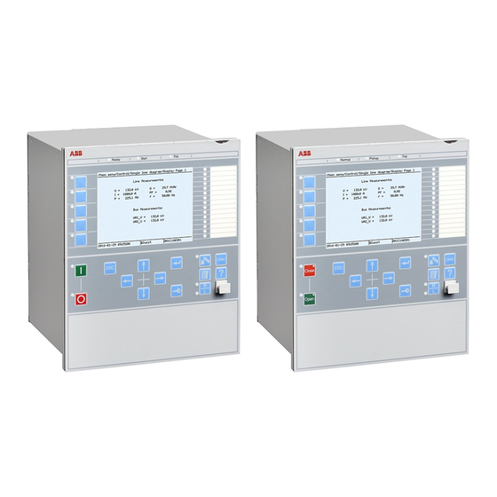
9.1.1 Front side of the IED GUID-AB024D16-C2C5-422E-82B2-26F522CFAAE6 v1 GUID-54166097-76E0-42A6-ADA7-D8580D1B2B1D V1 EN-US Figure 19: Front view of 6U half 19” IED The LHMI includes a monochrome LCD of 320x240 pixels. 650 series Installation manual © Copyright 2011 ABB. All rights reserved... -
Page 52: Rear Side Of The Ied
Section 9 1MRK 514 014-UUS A Technical data 9.1.2 Rear side of the IED GUID-6F8BF42A-3123-4F38-A211-EA700113F5BA v6 GUID-A87FAB18-230C-4DBC-B13E-81DAE22DEA73-ANSI V1 EN-US Figure 20: Rear view of 6U half 19” Dimensions GUID-33B28FB3-7FCF-4DEC-A194-C79D725805D6 v5 650 series Installation manual © Copyright 2011 ABB. All rights reserved... -
Page 53: Enclosure Class
GUID-59B01F47-1193-4243-B78C-EC6149CFA107 v13 Table 6: Degree of protection of flush-mounted IED Description Value Front side IP 40 Table 7: Degree of protection of the LHMI Description Value Front and side IP40 650 series Installation manual © Copyright 2011 ABB. All rights reserved... -
Page 55: Accessories And Ordering Data
Dimensions for screw holes GUID-87C934B9-C35C-4424-9516-4BFB61146EE5 V1 EN-US Figure 21: Flush mounting frame Table 8: Mounting kit Items Order number Flush mounting kit for one 6U half 19” housing IED 1KHL400228R0001 650 series Installation manual © Copyright 2011 ABB. All rights reserved... -
Page 56: Rack Mounting Kit For A Single Ied
Items Order number 19" rack mounting kit for one 6U half 19” housing IED 1KHL400239R0001 10.1.3 Rack mounting kit for two IEDs GUID-6B8520E4-D0F2-4B56-93DE-4F4377A1FA9C v1 • Mounting brackets • Screws 650 series Installation manual © Copyright 2011 ABB. All rights reserved... -
Page 57: Wall Mounting Kit For An Ied
19" rack mounting kit for two 6U half 19” housing IEDs 1KHL400240R0001 10.1.4 Wall mounting kit for an IED GUID-90374D4B-2485-40B0-8AF7-D8FEC47874BA v1 • Mounting brackets • Screws • Dimensions for screw holes 650 series Installation manual © Copyright 2011 ABB. All rights reserved... -
Page 58: Wall Mounting Kit For A Main Unit
Wall-mounting kit (cabling towards the mounting wall) for one 6U half 19” housing IED 1KHL400200R0001 10.1.5 Wall mounting kit for a main unit GUID-0F5249BD-54F1-4A9A-86B5-CE84EE4B57B1 v1 • Mounting brackets • Screws • Dimensions for screw holes 650 series Installation manual © Copyright 2011 ABB. All rights reserved... - Page 59 Optional cables for external display module Items Order number LHMI cable (1m) 1KHL380031R0100 LHMI cable (2m) 1KHL380031R0200 LHMI cable (3m) 1KHL380031R0300 LHMI cable (4m) 1KHL380031R0400 LHMI cable (5m) 1KHL380031R0500 650 series Installation manual © Copyright 2011 ABB. All rights reserved...
- Page 61 Central processor unit Carrier receive Cyclic redundancy check CROB Control relay output block Carrier send 650 series Installation manual © Copyright 2011 ABB. All rights reserved...
- Page 62 Electrical and functional description for digital lines used by local telephone companies. Can be transported over balanced and unbalanced lines Communication interface module with carrier of GPS receiver module Graphical display editor within PCM600 650 series Installation manual © Copyright 2011 ABB. All rights reserved...
- Page 63 Ingression protection, according to IEC standard, level IP40-Protected against solid foreign objects of 1mm diameter and greater. IP 54 Ingression protection, according to IEC standard, level IP54-Dust-protected,protected againstsplashing water. 650 series Installation manual © Copyright 2011 ABB. All rights reserved...
- Page 64 Parameter setting tool within PCM600 PT ratio Potential transformer or voltage transformer ratio PUTT Permissive underreach transfer trip RASC Synchrocheck relay, COMBIFLEX Relay characteristic angle RFPP Resistance for phase-to-phase faults 650 series Installation manual © Copyright 2011 ABB. All rights reserved...
- Page 65 FTP, UDP and RDP. TNC connector Threaded Neill-Concelman, a threaded constant impedance version of a BNC connector TPZ, TPY, TPX, TPS Current transformer class according to IEC User management tool 650 series Installation manual © Copyright 2011 ABB. All rights reserved...
- Page 66 Three times zero-sequence current. Often referred to as the residual or the -fault current Three times the zero sequence voltage. Often referred to as the residual voltage or the neutral point voltage 650 series Installation manual © Copyright 2011 ABB. All rights reserved...
- Page 68 ABB AB Substation Automation Products SE-721 59 Västerås, Sweden Phone +46 (0) 21 32 50 00 Scan this QR code to visit our website www.abb.com/substationautomation © Copyright 2011 ABB. All rights reserved.