
Related Manuals for tau K126MA


Summary of Contents for tau K126MA
- Page 1 GUIDA ALL’INSTALLAZIONE INSTALLATION GUIDE INSTALLATIONSANLEITUNG NOTICE D’INSTALLATION GUÍA PARA LA INSTALACIÓN GUIA DE INSTALAÇÃO K126MA IT - Istruzioni originali...
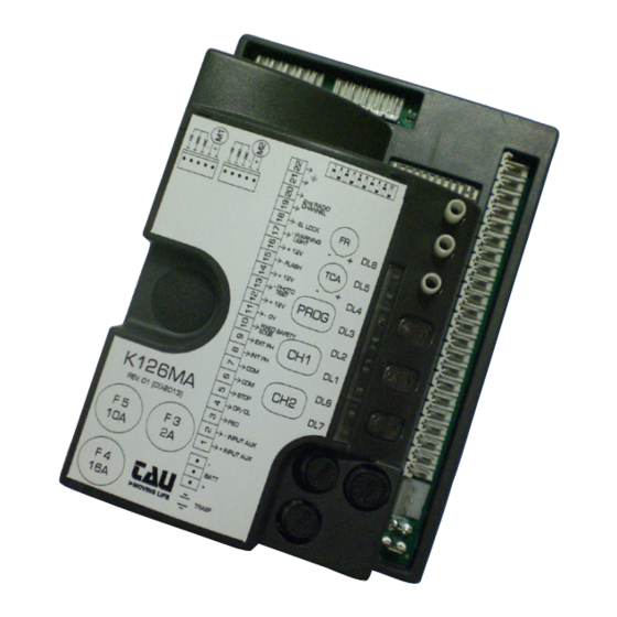
- Page 2 SCHEMA K126MA SCHALTPLAN SCHÉMA ESQUEMA DEL ESQUEMA CABLAGGIO WIRING DER K126MA CÂBLAGE CABLEADO DE LIGAÇÕES K126MA DIAGRAM K126MA K126MA K126MA Dip-switches 9 10 11 12 Trimmer: RALL 9 10 11 12 RALL K126MA PROG LEDs: FIXED SAFETY EDGE EXT. PHOTO INT.
-
Page 3: Power Supply
Aerial Gate open Courtesy light warning light 18V 3W max. max. 3W Flashing External 2nd radio light Photocells 0 11 12 channel 18V DC 1 2 3 4 5 max. 20W + 18 V + 18 V + 18V Fixed safety edge Ext. -
Page 4: Installation
WARNINGS This manual is designed to assist qualified installation personnel only. It contains no information that may be of interest to final users. This manual is enclosed with control unit K126MA and may therefore not be used for different products! Important warnings: Disconnect the mains power supply to the board before accessing it. -
Page 5: Technical Characteristics
STRIAN, etc.), in order to avoid gate malfunctions, it will be necessary to uncouple the various controls using RELAYS or using our 750T-RELE device. 2. INTRODUCTION The K126MA board has two working modes, selectable through the J6 jumper (see wiring diagram). J6 Jumped: standard mode, i.e. the control unit is powered all the time;... - Page 6 OPEN/CLOSE button N.O. input – Controls the opening and closing of the 4 - 6 OPEN/CLOSE automation and is regulated based on the function of dip-switches 2 and 4. (4= O/C - 6= COM) STOP button N.C. input – Stops the automation in any position, temporarily pre- venting the automatic closure, if programmed.
- Page 7 plug-in radio-receiver aerial input , for 433.92 MHz receivers only. (21= 21 - 22 AERIAL GROUND - 22= SIGNAL) motor (M2) supply output 18V DC max. 300 VA. 23 - 24 MOTOR (M2) (23= POSITIVE - 24= NEGATIVE) See note below. 25 - 26 - 27 ENCODER (M2) Not in use motor (M1) supply output 18V DC max.
- Page 8 when the automation is operating, a sequence of opening/closing commands causes the automation to OPEN-CLOSE-OPEN-CLOSE, etc. 2 / 4 STROKE in the same conditions, the same sequence of commands causes the automation to OPEN-STOP-CLOSE-STOP-OPEN-STOP, etc . (step-by step function) (see also dip switch 4). after the photocell is activated (input 7 - 9), the automation closes au- CLOSES AGAIN tomatically after 5 seconds.
-
Page 9: Obstacle Detection
(the system does not start any safety operation, it just stops the motors). Make sure you don’t stand near the automation during saving. 7. K126MA CHARACTERISTICS TIMER-OPERATED OPENING AND CLOSING CYCLES The opening/closing of the automation can be controlled by means of a timer that has a free N.O. -
Page 10: Diagnostics Led
8. DIAGNOSTICS LED DL1 - Red PEDESTRIAN button LED signal DL2 - Red OPEN/CLOSE button LED signal DL3 - Green STOP button LED signal DL4 - Green INTERNAL PHOTOCELLS LED signal DL5 - Green EXTERNAL PHOTOCELLS LED signal DL6 - Green SENSITIVE EDGE LED signal LED - DL7 Apart from highlighting the presence of the battery, LED DL7 displays any mistakes with a series of... - Page 11 Check wiring, check encoder by TEST-ENCODER (optional); no motor 1 signal; 4 (red) flashes: Check wiring, check the motor rotates freely and is powered directly by the battery, check fuse F5; no motor 2 signal (in case of failure of motor 1 wire terminal 4 (yellow) flashes: and with dip # 10 set in ON);...
- Page 12 and slowly open until the laef reaches its fully opened position. Auto Close function will be deactivated until a further command pulse is given. In case of 5 consecutive safety interventions the controller will progressively increase the Auto Close delay. Once the closing has been succesfully achieved, the Auto Close delay will go back to standard setting.
-
Page 13: Memory Capacity
2_ the (green) DL8 LED is ON to indicate the code learning mode has been activated (if no code is entered within 10 seconds the board exits the programming function); 3_ press the button of the relative radio control device; 4_ the (green) DL8 LED turns off to indicate saving is complete and then on again immediately wait- ing for other radio control devices (if this is not the case, try to re-transmit or wait 10 seconds and restart from point 1);... -
Page 14: Hard Reset
13. GUARANTEE: GENERAL CONDITIONS TAU guarantees this product for a period of 24 months from the date of purchase (as proved by the sales document, receipt or invoice). This guarantee covers the repair or replacement at TAU’s expense (ex-works TAU: packing and trans- port at the customer’s expense) of parts that TAU recognises as being faulty as regards workmanship... - Page 15 MANUFACTURER’S DECLARATION OF INCORPORATION (in accordance with European Directive 2006/42/EC App. II.B) Manufacturer: TAU S.r.l. Address: Via E. Fermi, 43 36066 Sandrigo (Vi) ITALY Declares under its sole responsibility, that the product: Electronic control unit designed for automatic movement of:...