Advertisement
Quick Links
Advertisement

Related Manuals for Samsung S-Box


Summary of Contents for Samsung S-Box
- Page 1 Samsung Electronics LED Display Installation Manual S-Box : SBB-SNOWRAF...
- Page 2 Check first before Installation Samsung Electronics • All Power cables and OCM cables must be connected firmly. • Install SNOW-RAF with the appropriate Cabinet. ※ Please check below Cabinet and S-Box compatibility table information. S-Box SNOW-RAF SNOW-1810U SNOW-JMU Cabinet IE025R,...
- Page 3 Components Samsung Electronics...
- Page 4 AC 100 to 240(50Hz/60Hz) AC 100 to 240(50Hz/60Hz) - UHD Resolution Support - FHD Resolution Support - Maximum 100m image transmission through HDBT - S-Box Grouping (Framelock) not supported transmission - Maximum 3m image transmission through direct Special Special Feature - LED HDR –...
- Page 5 Table of Contents Samsung Electronics 1. S-BOX Installation and Connection 2. Settings and How to Use 3. Issue and Solution [Appendix] S-BOX Wall Installation...
- Page 6 1. S-BOX Installation and Connection Samsung Electronics • S-BOX Installation Precautions ① Do NOT install the device upside down, ② Make sure the vent is not blocked to prevent the device from overheating. ③ If installing the device close to wall, make sure that there is a space of at least 50mm between the wall and the four sides of the device to ensure good ventilation.
- Page 7 Install the product in accessible place to facilitate operation and maintenance. ⑧ Expected installation cases are shown below. - When installed in a wall, it maintains a space above S-Box length (153.8m) + ventilation space (50mm). - Install it considering the length of the OCM Cable. • In the wall •...
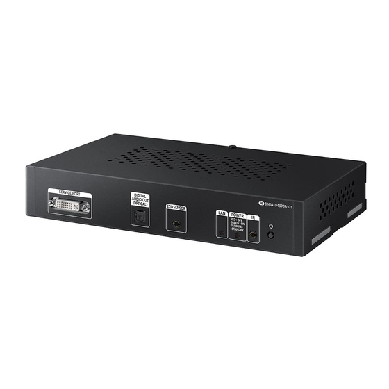
- Page 8 1. S-BOX Installation and Connection Samsung Electronics • S-BOX Product Picture SNOW-RAF Front SNOW-RAF Rear...
- Page 9 ① Input the video signal to the S-Box. (Input terminal : HDMI, USB) ② Connect from DATA OUT port of S-BOX to DATA IN port of the first cabinet using OCM Cable. ③ SNOW-RAF displays the screen starting from the upper left cabinet.
- Page 10 1. S-BOX Installation and Connection Samsung Electronics • S-BOX Connection...
- Page 11 1. S-BOX Installation and Connection Samsung Electronics • S-BOX Connection (Redundancy) ① If Redundant Spec should be used, Connect from DATA IN(Reverse) port of S-Box to DATA OUT port of the last cabinet by using OCM Cable.
- Page 12 Samsung Electronics • S-BOX Connection (External IR Receiver) - Connect the provided IR receiver to the IR terminal on the front of the S-Box. ※ Only one external IR receiver is provided for a set. ※ Turn off the S-Box and connect it.
- Page 13 1. S-BOX Installation and Connection Samsung Electronics • S-BOX Connection (External Ambient Light Sensor) – If necessary - Connect the provided external ambient light sensor to the Eco Sensor terminal on the front of the S-Box. ※ Only one external ambient light sensor is provided for a set.
- Page 14 Samsung Electronics • S-BOX Connection (RS232C) – If necessary - Connect the RS232C adapter provided on the RS232C IN terminal on the rear of the S-Box. - If necessary, connect to PC and use it for initial network setting or debug.
- Page 15 If DHCP is used, IP address is changed automatically and LSM can be disconnected. The 192.168.10.x band is used for internal communication of the LED Cabinet. Please use IP another IP band (except 192.168.10.x band) Do not assign the temporary IP, assign the S-Box IP (1 EA) through IT manager.
- Page 16 • The LED display model to be installed and the optimized image quality setting are automatically set after LSM connection is set. • For the best picture quality, make sure to connect/register S-Box and LED display with LSM SW. • The LED Display must be connected to OCM.
- Page 17 1. S-BOX Installation and Connection Samsung Electronics ② Setup the resolution of input PC PC : Click the right button of mouse → Click Screen resolution → Click Advanced settings Click “Monitor” tap → Monitor Settings → Setup “Screen refresh rate” to 60Hz...
- Page 18 • S-BOX Connection (Service port) ① The service port is dedicated port for monitoring to check the usage of OSD and the source being played at the initial installation of the S-BOX. ② Service port has FHD (1920*1080 @60Hz) resolution.
- Page 19 2. Settings and How to Use Samsung Electronics 2-1. Control Program for PCs LSM(LED Signage Manager) LSM Download Path : GSBN - SLM - Display solution download -> "LED SIGNAGE MANAGER" or "LSM“ • - GSBN : http://v3.samsunggsbn.com/ep...
- Page 20 Ethernet PC and S-box should be connected through Ethernet connection. Control PC S-Box is connected to the first LED Cabinet using OCM cable. Video + control signal LED cabinets are connected in daisy chain method using OCM cable. Cabinet 1...
- Page 21 2. Settings and How to Use Samsung Electronics 2-1. Control Program for PCs LSM(LED Signage Manager) Start– Login Page • If the LSM gets operated for the first time, the page to set the password will appear. To set the password, users have to input the same password two times and then click the “Start”...
- Page 22 Search function or input the IP address by yourself. If you click on the Search button, the IP address of S- Box on the same network is automatically retrieved. It is possible to add S-Box connected to IPv6 through IPv6 checkbox. If you click Add button, the relevant connection information will be added on Setup and Connect.
- Page 23 New Connection-Connect • Connection information of S-Box is generated in Setup and Connect. You can select the S-Box type to use by selecting the Model Type. Model Type is provided with a total of 4. (Without Cabinet IP / With Cabinet IP (FHD) / With Cabinet IP...
- Page 24 It shows the input source, It shows the layout, number, connected It shows the LED cabinet ID and resolution, and connection number of all LED cabinets and the its contents in error state. time information of S-BOX. number of disconnected cabinets.
- Page 25 2. Settings and How to Use Samsung Electronics 2-1. Control Program for PCs LSM(LED Signage Manager) Main Window-Edit Connection Layout Window • Connection layout: It adjusts the position and layout of each LED cabinet in the output source of the LSB.
- Page 26 Connection layout (View Port): Check the location and layout of each LED cabinet Category View: Home / Connections tap and configuration Device Information/Setting View: Change S-BOX setting (Screen setting, etc.) Sub Information View: Displays: Monitoring log, S-BOX and LED cabinet information...
- Page 27 2. Settings and How to Use Samsung Electronics 2-1. Control Program for PCs LSM(LED Signage Manager) Main Window-Connection Window - Device Information/Setting View • 1. Basic : . Power, Input Source, Screen Mute / Freeze 2. Picture . Picture Mode, Brightness, Contrast,...
- Page 28 2. Settings and How to Use Samsung Electronics 2-1. Control Program for PCs LSM(LED Signage Manager) Main Window-Connection Window - Device Information/Setting View • 6. Cabinet Settings . LOD Recheck, Pixel RGB Data(Reload, Request), Onscreen Display, Gamut, Backlight, Software Update, Reset Cabinet 7.
- Page 29 2. Settings and How to Use Samsung Electronics 2-1. Control Program for PCs LSM(LED Signage Manager) Main Window-Connection Window - Sub Information View • Monitor Window: MDC communication log and connection device information can be extracted as a verifiable file.
- Page 30 2. Settings and How to Use Samsung Electronics 2-1. Control Program for PCs LSM(LED Signage Manager) Main Window-Preference • Options - Command Retry Count - Error Status Interval - Temperature Alert Support - Program Language - Advanced Log Management - Notify device error by mail...
- Page 31 3. Issue and Solution Samsung Electronics S-Box Network Connection Issue with LSM ① When you can‘t find S-Box or see disconnected message in LSM -. Check Ethernet cable connection -. Check IP setting of S-Box -. Check target IP of S-Box in LSM -.
- Page 32 [Appendix] S-BOX Wall Installation Samsung Electronics • S-BOX Wall Installation Precautions ① Check the installable wall and install it using screws that fit the wall material. (Satisfied with more than 3kg of load) ② Install the Service Port upward as shown below.