Advertisement
Quick Links
1. Specifications ..................................................................... 1
2. Names of Parts .................................................................. 2
3.Disassembly/Reassembly ...................................................... 3
4.Printed Circuit Board ............................................................ 4
5. Schematic Diagrams ............................................................ 5-7
6. Exploded View .................................................................. 8
7.Replacement Parts List ......................................................... 9,10
1. Specifications
Item
Power Supply Input
Expansion Bus Connector
Physical Dimensions
(Width × Depth × Height)
Weight
Operating Environment
Temperature / Humidity
This service information is designed for experienced repair technicians only and is not designed for use by the general public. It does not
contain warnings or cautions to advise non-technical individuals of potential dangers in attempting to service a product. Products powered
by electricity should be serviced or repaired only by experienced professional technicians. Any attempt to service or repair the product or
products dealt with in this service information by anyone else could result in serious injury or death.
CONTENTS
Description
DC 15.6 V [Do not use other than the specified
AC adapter (Model No.: CF-AA1639A)].
100-pin
342 mm × 130 mm × 66 mm
(13.5" × 5.1" × 2.6")
Approx. 1.5kg (3.3 lb.)
5 to 35 °C (41 to 95 °F) / 30 to 80 % RH
(no condensation)
WARNING
-1-
ORDER NO. CPD0011002C1
G22
CF-VEB481
This is the Service Manual for
the following areas.
W ...for all areas.
©
2000 Matsushita Electric Industrial Co., Ltd.
All rights reserved. Unauthorized copying and
distribution is a violation of law.
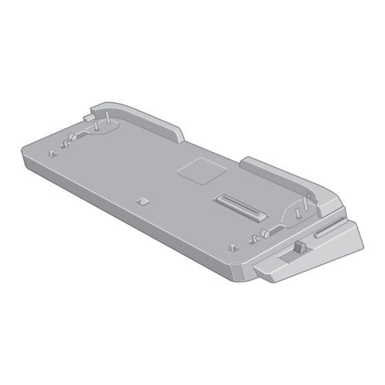
Port Replicator
Advertisement

Summary of Contents for Panasonic CF-VEB481
-
Page 1: Table Of Contents
ORDER NO. CPD0011002C1 Port Replicator CF-VEB481 This is the Service Manual for the following areas. W ...for all areas. CONTENTS 1. Specifications …………………………………………………………… 1 2. Names of Parts ………………………………………………………… 2 3.Disassembly/Reassembly ……………………………………………… 3 4.Printed Circuit Board …………………………………………………… 4 5. Schematic Diagrams …………………………………………………… 5-7 6. -
Page 2: Names Of Parts
CF-VEB481 2. Names of Parts Rear Keyboard Port DC-IN Jack LAN Port Parallel Port DC IN 15.6V Mouse Port Display Port Microphone Jack Serial Port USB Port Security Lock Headphone Jack LOCK Check whether the connectors are point- ing up or down. -
Page 3: Disassembly/Reassembly
CF-VEB481 3. Disassembly/Reassembly CAUTION: Be careful when disassembling and servicing since some chassis may have sharp edges. Note: Before disassembling, be sure to do the following procedures first. 1. Power off the computer and disconnect it. 2. Unplug the AC adaptor from DC-IN Jack. -
Page 4: Printed Circuit Board
CF-VEB481 4. Printed Circuit Board 4.1 Main PCB –4–... -
Page 5: Schematic Diagrams
CF-VEB481 5. Schematic Diagrams Main 1 DC-IN TP14 TP17 PR15 DFJJB3Z07ZAH R451_07.0 7.0A BLM41P600S 0.1u 0.1u 0.1u HEC3900-01-010 To CF-48 Hoshiden USB Port 0 PR15 WD-100P4V-VF120-N-T45 TP23 USBPW0 0.1u PR_TD+ 001:E3 PR_TD- BLM41P600S 001:E3 C111 PR_RD+ L101 0.1u 001:E3 PR_RD-... - Page 6 CF-VEB481 Main 2 Microphone VC5SA R404 TP15 VC5SA R401 R405 C408 C402 0.1u SNDGND SNDGND SNDGND TP18 NJM2904M C401 IC401 TP13 PRMIC R402 R403 2.2K 2.2K 001:B7 SNDGND C407 DFJJD5S14ZAH L401 BK1608HS601 0.22u R406 L402 BK1608HS601 TP16 L403 BK1608HS601 L404...
- Page 7 CF-VEB481 Main 3 Parallel Port TP42 TP51 TP54 TP58 TP61 TP40 TP49 TP53 TP56 TP59 DFJS033ZA025 PRSTRB# BLM11A121S L601 PRAUTO# BLM11A121S L602 PRPD0 BLM11A121S L603 ERROR# BLM11A121S L604 PRPD1 BLM11A121S L605 PINIT# BLM11A121S L606 PRPD2 BLM11A121S L607 SLCTIN# BLM11A121S L608...
-
Page 8: Exploded View
CF-VEB481 6. Exploded View K104 K107 K108 K101 K108 K104 K108 K107 K106 K106 K106 K107 K108 K105 K103 K103 K105 K103 K102 K102 –8–... -
Page 9: Replacement Parts List
CF-VEB481 7. Replacement Parts List Note: Important Safety Notice Components identified by mark have special characteristics important for safety. When replacing any of these components, use only manufacturer’s specified parts. REF. NO. PART NO. DESCRIPTION Q’TY Main Block Unit DL3UP1108AAA... - Page 10 CF-VEB481 REF. NO. PART NO. DESCRIPTION Q’TY C503 504 505 601 602 ECUV1H330JCV CAPACITOR, 50 V, 33 pF 603 604 605 606 607 608 609 610 611 612 613 614 615 616 617 DFJP227ZA100 CONNECTOR, FOR EXPANSION BUS PORT CN2 3...


