Oberheim Matrix-1000 Owner's Manual
Analog sound module
Hide thumbs
Also See for Matrix-1000:
- Owner's manual (64 pages) ,
- Owner's manual (33 pages) ,
- Owner's manual (33 pages)
Advertisement
Quick Links
Advertisement

Related Manuals for Oberheim Matrix-1000


Summary of Contents for Oberheim Matrix-1000
- Page 1 • • N ER'S MAN UAL scanned at . wolzow.com...
- Page 2 NER'S MANUAL Second Edition - July, 1988 ©1988 Oberheim - All Rights Reserved. Reproduction in Whole or in Part is Prohibited Without Express Written Permission. "Oberheim•, the Oberheim Logo, Matrix-1000, Matrix-6, Matrix-SR, Matrix-12, Xpander and DPX-1 are trademarks of ECC Development Corporation.
- Page 3 Operation of this equipment in a residential area is likely to cause interference in which case the user his own expense will be required to take whatever measures may be required to correct the interference. Matrix-1000 Owner's Manual...
- Page 5 Matrix-1000 Owner's Manual...
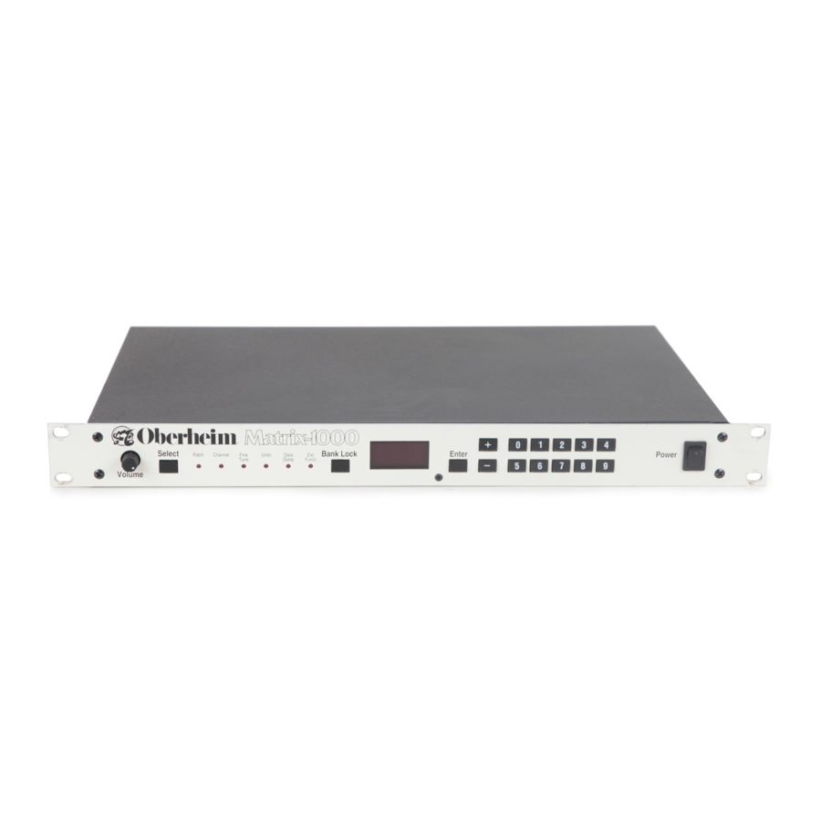
- Page 6 It is specifically designed to allow the musician to play the best 1000 sounds of the famous Oberheim Matrix-6. Musicians at all levels will love the Matrix-1000's simplicity of operation - & just select the Bank Patch Number and play : But its simplicity is really quite misleading.
- Page 7 • oi::: :I � � � • @ .. @� @� Fl .: � -· • • ..Oi::: :I � �r • '¢=' • ..€i3 • • " ;;. :! 0 • " > Matrix-1000 Owner's Manual...
- Page 8 IF YOU'RE IN A HURRY ..I N ITIAL SET UP - Place the Matrix-1000 on any level surface, or mount it in a rack cabinet. When rack-mounting the Matrix-1000, be sure to leave space • above and below the unit to insure proper ventilation.
- Page 9 Matrix-1000. These brief procedures are explained in detail throughout the rest of the manual. We encourage you to read the manual in its entirety if you would like to learn more about the Matrix-1000. Matrix-1000 Owner's Manual...
-
Page 10: Rack Mounting
The Matrix-1000 uses one standard rack space (1 -3/4 inches). We recommend leaving an air space of approximately 1/2-inch between the Matrix-1000 and other units in the rack, to prevent overheating. This is especially important if the Matrix-1000 will be left powered on for long periods of time. - Page 11 (guitar cord) with a 1/4-inch plug . The Matrix-1000 can be plugged into a Line Input, or an attenu ated Microphone Input. Connect the Matrix-1000 to your sound...
- Page 12 MIDI IN of the Matrix- 1000, using a standard MIDI interface cable. The MIDI Channel must be the same for both your Master instrument and the Matrix-1000, or else the Matrix-1000 must be in OMNI or MONO Mode. MIDI Channel selection is described under Channel mode in Chapter 2.
-
Page 13: Care And Maintenance
For proper care and handling, do not expose your Matrix-1000 to direct sunlight or to temperatures above 120° F (48.9° C). Be careft•I not to spill any liquids on or into the Matrix-1000. Do not expose the Matrix-1000 to moisture or store it in an area that is damp or has high levels of humidity. - Page 14 Height (top-to-bottom) 1 .75 in. ( 4.45 cm.) 1 Rack Space including feet 2.03 in. ( 5. 1 6 cm.) Net Weight 9 lbs., 4 oz. ( 4.20 kg.) ( 5.90 kg.) Shipping Weight 1 3 lbs. Specifications are subject to change without notice. Matrix-1000 Owner's Manual...
- Page 15 Matrix-1000 Owner's Manual...
- Page 16 Number key to change the bank. Bank Lock to jump immediately back to Patch In any other mode, press mode. Bank Lock Bank Lock key also acts as a mute switch. Pressing any time immediately silences the Matrix-1000. Matrix-1000 Owner's Manual...
- Page 17 + and - or the Ext. Funct., Number keys. In the Number keys select the different Extended functions, and only the + and - keys may be used to change values. Matrix-1000 Owner's Manual...
- Page 18 This is the mode you will use most often. I n this mode, the display shows which of the 1000 sounds you are playing. Patches are numbered through 999. You can change patches either from the Matrix-1000 front panel or from MIDI .
- Page 19 If your Master instrument has patch numbers which start at 1 rather than 0, then patch 01 on the Master selects patch 00 of the selected bank on the Matrix-1000, patch 02 on the Master selects patch 01, etc. Matrix-1000 Owner's Manual...
- Page 20 Matrix-1000. For instance, suppose patch 322 is selected on the Matrix-1000. Hold the Vibrato control and select patch 4 on the Master. The Matrix-1000 selects bank 4, so the patch changes from 322 to 422. If your Master has patch numbers which start at 1 rather than O, then patch 1 selects bank 0, patch 2 selects bank 1, etc.
- Page 21 • the Matrix-1000 receives messages on all channels, and transmits on channel 1. Displays f ram G 1 to G9 mean that the Matrix-1000 is in • MONO mode (MIDI mode 4), with basic channels 1 through 9. The G here stands for guitar, since MONO mode is usually used with guitar controllers to allow independent pitch bend on each string.
- Page 22 Master instrument is not sending Mode Change Messages. Refer to the following chart to determine the Voice-to-Channel assign ments of the nine MIDI MONO modes of the Matrix-1000. Notice that G9 is the top MIDI Channel represented. The Matrix-1000 does not operate in MIDI MONO for Channels 10 through 16.
- Page 23 FINE TUNE The Matrix-1000 is normally tuned to Standard Pitch of A= 440 Hz, but it can be adjusted to match the tuning of other instru ments in your system. • -� Select Patch Channel Fine Units Data Tune Dump...
- Page 24 TRANSPOSE, UNISON, MIDI ECHO Ext. Funct. mode of the Matrix-1000 contains Extended Functions. There are presently eight of these functions, numbered O through 7 and they are not saved with each patch, although they are saved when you turn the power off. Nu111bers O through 2 are the ones you will need most often.
- Page 25 Voice monophonically. Unison plays all six Voices together as a single note. This is why the Matrix-1000 sounds richer and louder in Unison mode. When you play legato, the sound may or may not retrigger. This is programmed as appropriate for each patch.
- Page 26 Press + to turn MIDI echo on. Now do the same on the second Matrix-1000. Since the third Matrix-1000 is the last in line, you do not need to turn on its echo. MIDI That's it! Now when you play a note on your Master instrument, •...
- Page 27 Play the sound at different places on the keyboard. • The bottom line is Exper i m ent. The Matrix-1000 is one of the world's most dynamic synthesizers and can do some very unusual things. Programmers have taken advantage of this, so...
- Page 28 Chapter3: ABOUT THOSE 1000 PATCHES ... At the heart of the Matrix-1000 is the same circuitry used to produce the sounds in the Oberheim Matrix-G keyboard and the Matrix-GR rack mount synthesizer. Recent advances in technology have permitted the same rich sounds to be packaged in a 1-rack space unit at a considerably lower cost.
- Page 29 If the display shows Pro instead of st o when you press Enter, the memory has been protected. Memory Protect must be turned off before any patches can be copied or stored. See Ext. Funct. #6. Chapter 4 under Matrix-1000 Owner's Manual...
- Page 30 Here is how to set up for two Matrix-1 OOOs. The procedure is basically the same when more units are added. The first Matrix-1000 considered the Group Master. The other Matrix-1 OOOs are slaves. All are performed on the Group Master operations in the setup procedure only.
- Page 31 • mode, the first note plays on the first Matrix-1000, the second note plays on the second Matrix-1000, the third note plays back on the first, the fourth note goes to the second, etc. We call this note assignment ''Alternating Rotate''.
- Page 32 For even greater flexibility, you can program each patch on the Group group mode. Master to use or ignore The Matrix-1000 is shipped from group mode. factory with all patches programmed to use If you want group mode.
- Page 33 Matrix-G or Matrix-GR to make a 12-voice instrument: You must have Matrix-G/GR software revision 2.13 or • later. Connect Matrix-G MIDI OUT to Matrix-1000 MIDI IN, and • Matrix-1000 MIDI Out to Matrix-G MIDI IN. OR, Connect Master to Matrix-1000 MIDI IN, and Matrix-1000 MIDI OUT to Matrix-GR MIDI IN.
- Page 34 Units Tune Fune Saving Patches: Dumping the Matrix-1 000 FROM Connect the MIDI OUT of the Matrix-1000 to the MIDI IN of the • receiving device. Make sure that MIDI System Exclusive is enabled on the receiv • ing device.
- Page 35 (Ext. Funct. Make sure that Memory Protect #6) is • turned off on the Matrix-1000. If Memory Protect is on when the Matrix-1000 receives a patch dump, it will ignore the dump. Execute the desired function from the transmitting •...
- Page 36 1000. The received patches are now available. Note that Matrix-6 and 6R units with software version 2.13 or earlier may transmit patches faster than the Matrix-1000 can receive them during a SEND ALL. The result may be that some patches are not successfully transferred.
- Page 37 Pedal 1 MIDI controller P Ed select. Displays the Unit Number group mode. used in Po n Memory Protect is ON. Memory Protect is OFF. Po t t st Test mode. Bend Range. b nd Matrix-1000 Owner's Manual...
- Page 38 Invert MIDI Volume The Matrix-1000 normally gets louder as MIDI Volume (Controller #7) is Invert MIDI Volume is on, the Matrix-1000 gets softer increased. When as MIDI Volume is increased. This may seem rather strange, but it allows two rather nice effects: Whammy bar.
- Page 39 Group Master is considered unit 0, the first slave Matrix-1000 in the Group is unit 1, the next is unit 2, etc. The Group Master transmits notes to each slave on the MIDI channel number corresponding to the slave's unit number . . For instance, notes for slave unit 1 are transmitted on channel 1.
- Page 40 Test Mode The Matrix-1000 software includes a number of test routines used during Ext. Fu nct. manufacture and servicing. To access these functions, select Enter. #7 and press The display will then show the test number. The+ and - keys change the test number.
- Page 41 RE-INITIALIZATION In the unlikely event that your Matrix-1000 starts to behave strangely, you may wish to perform a complete re-initialization of Enter the memory. This can be accomplished by holding the button while turning the power on. This does not affect the...
- Page 42 All Notes Off 101 1 xxxx OMNI Mode Off 1 01 1 xxxx OMNI Mode On (OMNI is assumed off in MONO ON) 1 0 1 1 xxxx Mono Mode On 101 1 xxxx Mono Mode Off Matrix-1000 Owner's Manual...
- Page 43 System Common Messages 1 1 1 1 0000 System Exclusive - Oberheim ID 1 OH Matrix-6/6R/1 000 Device ID <Opcode> <data bytes> OF7H End of System Exclusive 1 1 1 1 01 1 1 End of System Exclusive System Real Time Messa ges...
- Page 44 <Value> = the val ue to which that parm shou ld be set. Note: All values are sign extended from bit 6 into bit 7 except for parameter 1 21 (VCF frequency). Range checking should be done on the value of each parameter before it is sent. Matrix-1000 Owner's Manual...
- Page 45 Note : The value is sign extended from bit 6 into bit 7. Range checking should be done on all data before it is sent. Unlock Bank FOH 1 OH 06H OCH F7H On receipt of this message, Bank Lock will be disabled. Matrix-1000 Owner's Manual...
- Page 46 (0 <ID> O if Group Mode is off Unit ID for target M-1 000 in Group Mode 7FH for any unit in Group Mode 268 nybbles transm itted + 5 bytes Header + 1 byte Matrix-1000 Owner's Manual...
- Page 47 DCO 2 Initial Pulse Width DCO 2 Fixed Modulations Bit 0 = Lever 1 Bit 1 = Vibrato DCO 1 Waveform Enable Bit O = Pulse Bit 1 = Wave Bit 2 = Noise DCO 2 Detune 6 (signed) Matrix-1000 Owner's Manual...
- Page 48 Single Trigger 2 = Multi Trigger = External Trigger LFO 1 Lag Enable LFO 1 Waveshape (see Table 1 ) LFO 1 Retrigger point LFO 1 Sampled Source Number LFO 1 Initial Amplitude LFO 2 Initial Speed Matrix-1000 Owner's Manual...
- Page 49 Env 2 Initial Decay Time Env 2 S ustain Level Env 2 Initial Release Time Env 2 Initial Amplitude Env 2 LFO Trigger Mode See Env 1 LFO Trigger Mode above Env 2 Mode See Env 1 Mode above Matrix-1000 Owner's Manual...
- Page 51 MM Bus 3 Amount 1 1 4 MM Bus 3 Destination 1 1 5 co(je (see Table 3) Matrix Modulation Bus 4 1 1 6 Source Code (see Table 2) MM Bus 4 Amount 1 1 7 7 (Signed) Matrix-1000 Owner's Manual...
- Page 52 M M Bus 8 Destination 1 30 code (see Table 3) Matrix Modulation Bus 1 3 1 Source Code (see Table 2) (Signed) MM Bus Amount 1 32 MM Bus Destination 1 33 code (see Table 3) Matrix-1000 Owner's Manual...
- Page 53 * The "O = Unused Modulation" parameter in this Table is found in the Modulation Source list only. This parameter is not a Tracking Generator input and thus will not be displayed in parameter 33 TRACK INPUT. Matrix-1000 Owner's Manual...
- Page 54 29 = LFO 1 Amplitude 1 4 = Envelope 1 Attack 30 = LFO 2 Speed 1 5 = Envelope 1 Decay 31 = LFO 2 Amplitude 1 6 = Envelope 1 Release 32 = Portamento Time Matrix-1000 Owner's Manual...
- Page 55 1 66 N umber of Units (Group Mode) 1 67 Current Unit Number (Group Mode) Group Mode Enable (In MSB only) 1 68 1 69 Unison Enable Volume Invert Enable 1 70 Memory Protect Enable 1 71 Matrix-1000 Owner's Manual...
- Page 56 Device ID FOH 7EH <Chan> 06H 02H <mfg> <fam-lo> <fam-hi> <memb-lo> <memb-hi> <rev-0> <rev-1 > <rev-2> <rev-3> F7H <Chan> = Transmitting device's Basic Channel <mfg> = 1 OH (Oberheim) <fam-lo> = 6H (Matrix-6/6R/1 000) <fam-hi> = OH <memb-lo> = 2H (Matrix-1 000) <memb-hi>...
- Page 57 40H, parameter is the registered pitch bend range. Thus, a data entry value will update the selected parameter to be while 3EH is inter preted as -2. This allows for transmission of negative numbers. Matrix-1000 Owner's Manual...
- Page 58 We strongly recommend that you read the following policy statements carefully and refer to the procedure at the end in obtaining service for your Oberheim product should it ever be needed. OBERHEIM L IMITED CUSTOMER WARRANTY...
-
Page 59: What Is Covered
Oberheim to verify the Warranty status of the product. If the Warranty has been verified, Oberheim will, without charge for parts or labor, either repair or replace the defective part(s). If the Warranty cannot be verified, the entire cost of the repair in parts and labor is the responsibility of the product's owner. -
Page 60: What Is Not Covered
Oberheim shall not be liable for costs involved in packing or preparing the product for shipping with regards to time, telephone call charges, labor or materials, shipping and freight costs, or time and expenses involved in transporting the product to and from an Oberheim Authorized Service Center, an Oberheim Authorized Dealer or the Oberheim Fac... - Page 61 Implied Warranty of Merchantability, applicable to this product. Oberheim shall not be liable for damage or loss resulting from the negligent or intentional acts of the shipper or his contract affiliates. The owner of the product should contact the shipper for proper claims procedures in the event of damage or loss result...
-
Page 62: How To Obtain Warranty Service
HOW TO OBTAIN WARRANTY SERVICE you have reason to believe that your Oberheim product is malfunction ing or otherwise not operating properly, do the following : CONTACT YOUR NEAREST ECC/OBERHEIM STEP AUTHORIZED SERVICE CENTER Telephone them as soon as the problem is discovered. Be prepared to discuss the problem as completely and accurately as possible. - Page 63 If you believe that the problem is still unresolved after you have contacted the Service Center and Dealer, contact the ECC/Oberheim National Offices. In an atterript to resolve your problem, we will work with your local Service Center or Dealer to review and verify the information and facts. Based on these facts, we will advise or consult with the Service Center or Dealer as appropriate.
- Page 64 • • • • scanned . wolzow.com at www...